EP0179349B1 - Drucksystem zum Aufbringen von Lösungsmitteln - Google Patents
Drucksystem zum Aufbringen von Lösungsmitteln Download PDFInfo
- Publication number
- EP0179349B1 EP0179349B1 EP19850112742 EP85112742A EP0179349B1 EP 0179349 B1 EP0179349 B1 EP 0179349B1 EP 19850112742 EP19850112742 EP 19850112742 EP 85112742 A EP85112742 A EP 85112742A EP 0179349 B1 EP0179349 B1 EP 0179349B1
- Authority
- EP
- European Patent Office
- Prior art keywords
- pressure
- vessels
- piston
- exhaust chamber
- solvent
- Prior art date
- Legal status (The legal status is an assumption and is not a legal conclusion. Google has not performed a legal analysis and makes no representation as to the accuracy of the status listed.)
- Expired
Links
- 239000002904 solvent Substances 0.000 title claims description 57
- 238000004891 communication Methods 0.000 claims description 16
- 238000013022 venting Methods 0.000 claims description 16
- 239000012530 fluid Substances 0.000 claims description 10
- 238000004811 liquid chromatography Methods 0.000 claims description 6
- 230000001105 regulatory effect Effects 0.000 claims description 4
- 230000001276 controlling effect Effects 0.000 claims description 2
- 239000007789 gas Substances 0.000 description 16
- 239000001307 helium Substances 0.000 description 14
- 229910052734 helium Inorganic materials 0.000 description 14
- SWQJXJOGLNCZEY-UHFFFAOYSA-N helium atom Chemical compound [He] SWQJXJOGLNCZEY-UHFFFAOYSA-N 0.000 description 13
- 238000007872 degassing Methods 0.000 description 4
- 239000000203 mixture Substances 0.000 description 3
- 239000002253 acid Substances 0.000 description 2
- 239000007788 liquid Substances 0.000 description 2
- 239000000463 material Substances 0.000 description 2
- 239000004698 Polyethylene Substances 0.000 description 1
- 150000007513 acids Chemical class 0.000 description 1
- 238000004458 analytical method Methods 0.000 description 1
- 238000013459 approach Methods 0.000 description 1
- 230000000712 assembly Effects 0.000 description 1
- 238000000429 assembly Methods 0.000 description 1
- 238000010586 diagram Methods 0.000 description 1
- 238000009792 diffusion process Methods 0.000 description 1
- 230000007613 environmental effect Effects 0.000 description 1
- 239000000383 hazardous chemical Substances 0.000 description 1
- 150000002371 helium Chemical class 0.000 description 1
- 230000000266 injurious effect Effects 0.000 description 1
- 238000000034 method Methods 0.000 description 1
- 238000012986 modification Methods 0.000 description 1
- 230000004048 modification Effects 0.000 description 1
- 238000012544 monitoring process Methods 0.000 description 1
- -1 polyethylene Polymers 0.000 description 1
- 229920000573 polyethylene Polymers 0.000 description 1
- 238000007789 sealing Methods 0.000 description 1
- 239000011877 solvent mixture Substances 0.000 description 1
Images

Classifications
-
- B—PERFORMING OPERATIONS; TRANSPORTING
- B01—PHYSICAL OR CHEMICAL PROCESSES OR APPARATUS IN GENERAL
- B01D—SEPARATION
- B01D15/00—Separating processes involving the treatment of liquids with solid sorbents; Apparatus therefor
- B01D15/08—Selective adsorption, e.g. chromatography
- B01D15/10—Selective adsorption, e.g. chromatography characterised by constructional or operational features
- B01D15/16—Selective adsorption, e.g. chromatography characterised by constructional or operational features relating to the conditioning of the fluid carrier
- B01D15/163—Pressure or speed conditioning
-
- G—PHYSICS
- G01—MEASURING; TESTING
- G01N—INVESTIGATING OR ANALYSING MATERIALS BY DETERMINING THEIR CHEMICAL OR PHYSICAL PROPERTIES
- G01N30/00—Investigating or analysing materials by separation into components using adsorption, absorption or similar phenomena or using ion-exchange, e.g. chromatography or field flow fractionation
- G01N30/02—Column chromatography
- G01N30/26—Conditioning of the fluid carrier; Flow patterns
- G01N30/28—Control of physical parameters of the fluid carrier
- G01N30/36—Control of physical parameters of the fluid carrier in high pressure liquid systems
-
- Y—GENERAL TAGGING OF NEW TECHNOLOGICAL DEVELOPMENTS; GENERAL TAGGING OF CROSS-SECTIONAL TECHNOLOGIES SPANNING OVER SEVERAL SECTIONS OF THE IPC; TECHNICAL SUBJECTS COVERED BY FORMER USPC CROSS-REFERENCE ART COLLECTIONS [XRACs] AND DIGESTS
- Y10—TECHNICAL SUBJECTS COVERED BY FORMER USPC
- Y10T—TECHNICAL SUBJECTS COVERED BY FORMER US CLASSIFICATION
- Y10T137/00—Fluid handling
- Y10T137/2931—Diverse fluid containing pressure systems
- Y10T137/3115—Gas pressure storage over or displacement of liquid
- Y10T137/3127—With gas maintenance or application
Definitions
- the invention relates to a solvent pressurization system for use in liquid chromatography, said system comprising a source of pressurized gas; a plurality of sealed vessels, said vessels being adapted to hold solvents therein; each said vessel having a gas input port, said vessels being located within a closable compartment; and a manifold being in communication with said pressurized gas from said gas source and with the vessels, and having fittings for each vessel; and venting means connectable with the vessels.
- liquid chromatography systems have evolved such that unattended analysis involves separating a particular sample a number of times but using a different solvent composition, or mixture each time. Alternatively, a variety of different samples can be analysed, each with a different solvent composition.
- a major advantage to pressurizing the solvent components is that air bubbles, usually found in nonpressurized systems, are eliminated. Consequently, since air bubbles tend to reduce the performance of the solvent pump, the entire liquid flow exhibits an increased efficiency.
- many solvents are acids or other hazardous materials and since any liquid under pressure is potentially injurious to both equipment and personnel, a number of potential dangers exist in present liquid chromatography solvent gradient systems.
- the present invention provides a solvent pressurization system of the above-mentioned type which is characterized in that a double manifold is provided having a distribution chamber in communication with said pressurized gas from said gas source and an exhaust chamber communicatable with said venting means, a set of fittings for each vessel for controlling the gas flow from said distribution chamber to said vessel and from said vessel to said exhaust chamber, each set of fittings including inlet valve means and outlet valve means and an element for concomitantly opening or closing both valve means.
- said inlet valve means includes an inlet pin having a longitudinal bore in fluid flow communication with its corresponding vessel and a radial bore connected to the longitudinal bore which is open to said distribution chamber when said inlet valve means is open, and closed to said distribution chamber when said inlet valve means is closed
- said outlet valve means includes an outlet pin having a longitudinal bore in fluid flow communication with said vent means and a radial bore connected to the longitudinal bore which is open to said exhaust chamber when said outlet valve means is open, and closed to said exhaust chamber when said outlet valve means is closed
- said element includes a latch plate which mechanically ties said inlet pin to said outlet pin.
- a preferred embodiment of said means for relieving pressure when the door is opened comprises a piston exposed to the pressure of said exhaust chamber, said piston being movable between a first position wherein said exhaust chamber is in fluid flow communication with said venting means and a second position wherein said exhaust chamber is out of communication with said venting means, said piston having a protuberance engageable with said door to move said piston between said positions responsive to the opening or closing of said door.
- means are provided for depressurizing said vessels when the pressure within said vessels exceeds a preselected venting pressure.
- said means for depressurizing comprises a piston exposed to the pressures of said exhaust chamber, said piston being movable between a first position wherein said exhaust chamber is in fluid flow communication with said venting means and a second position wherein said exhaust chamber is out of communication with said venting means, spring means engaging said piston to move said piston between said positions responsive to the fluid pressure in said exhaust chamber.
- the solvent pressurization system embodying the principles of the present invention is a stand alone solvent environmental control unit used for the pressurization and/or degassing of liquid chromatography solvents.
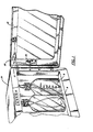
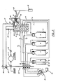
- four solvent vessels or bottles 9, Figs. 1 and 2 are enclosed in a compartment or cabinet 34 to permit safe pressurizing of the bottles.
- pressurizing capability is interlocked with the closing of the compartment door. Opening of the door 18 results in automatic depressurizing and the starting of sparging for degassing of the solvents, as will be discussed more fully hereinafter.
- the solvent pressurization system has two primary operating modes. During one operating mode the solvent vessels 9 are pressurized and solvent is delivered via a multi-port proportioning valve 36 to a chromatographic pump 38. This mode is hereinafter referred to as the delivery mode. During the other operating mode, gas is passed through the solvents for the purpose of removing air bubbles therefrom, i.e. a procedure commonly known as degassing or sparging.
- a supply of helium enters through a bulkhead fitting 1 on the back panel of the cabinet 34.
- a pressure such as, for example, about 5 p.s.i. secondary pressure.
- the regulator is fixed and can not be inadvertently adjusted by the operator. It will only change, for example, about plus or minus 1 p.s.i. secondary pressure for plus or minus 20 p.s.i. of primary pressure change.
- the gas continues through a check valve 3 and into a distribution chamber 5 of a double manifold 4.
- This input check valve 3 is required to prevent solvent back up should depressurization take place in the supply side while there exists a pressure in the bottles. That is, if the system has been operating long enough for pressure to build up to say, 5 p.s.i., for example, at the top of the bottles 9 and the helium supply is then disconnected, the pressure would then drop to zero only as far as the check valve. The 5 p.s.i. pressure would be maintained throughout the remainder of the system by the check valve. If there were no check valve present, the pressure would drop to zero all the way down to the filter 33 in the solvent. In that case the pressure in the bottle would force the solvent back up through the filter and all the way through the regulator and right out of the system.
- the check valve 3 also prevents flow back of the helium and vapors through the regulator 2.
- Figs. 3A and 3B each show a cross-section of the manifold 4 taken through both chambers 5 and 12 one set of fittings, which is the same for all four of the bottles 9.
- Fig. 3A shows the fittings in their operational position
- Fig. 3B shows the same fittings in their decoupled position or mode.
- the gas enters fitting or pin 6 through a radial hole or bore 7 in the pin when the valve is in its operational mode.
- the gas continues along an axial bore 32 in the pin into a polyethylene tube 8, which is pushed over the pin 6 and sealed therewith by virtue of its elastomeric properties.
- the gas travels down the tubes 8 to the bottles 9 and then is discharged through a porous cylinder 10 at the bottom of the bottle, where it sparges through the solvent and rises to the top.
- This helium exits at the top of the bottle 9 and travels through a tube 11 and enters an exhaust chamber 12, Fig. 3, through an axial bore 32' in a pin 13 having a radial hole or bore 7'.
- the helium pushes a piston 14, Fig. 2, back until its slotted edge 15 moves past an "0" ring 16, and then the helium runs out a vent line 17. Sparging will continue, degassing the solvents as long as the door remains open or until the pressure is shut off.
- the helium continues to sparge until the full regulated pressure of 5 p.s.i. is reached and then the helium will stop entering.
- the spring 20 has a constant which is selected such that, if the regulator fails and becomes open to primary pressure, the piston slots 15 move past the "0" ring 16 and vent the system at a suitable pressure such as, for example, between about 7 and about 13 p.s.i. which is a safe maximum pressure.
- a dial cord 21 is attached to the ball plunger 19 to follow the piston travel.
- the other end of the cord is attached to a pivoting lever 22, which also serves to multiply the motion by a preselected ratio.
- An indicator flag 23 is conveniently mounted for viewing from the front of the cabinet 34 and is calibrated, as desired.
- a bulkhead connector 26, Fig. 2 is provided on the backpanel of the cabinet or compartment 34 for that purpose. To use, the port sealing plug 27 is removed and the pressure gauge is attached.
- the system includes a feedback check valve 25, Fig. 2, to prevent differential pressure from occurring between the input chamber 5 and the exhaust chamber 12.
- the feedback check valve is used to equilibrate the pressure between P1, the pressure between the input check valve 3 and the solvent in. the bottle 9, and P2, the pressure above the solvent in the bottle.
- the pressure above the solvent in the bottle has been shown to rise due to an increase in temperature and/or due to the diffusion of the helium in the helium lines 8 leading to the bottles.
- valve means for the helium input line 8 and the valve means for the vent line, 11 are tied together so that manipulation of a single element or plunger opens or closes both valve means together.
- Fig. 3A shows the valving arrangement in its operational mode and Fig. 3B shows it in its decoupled mode.
- a latch plate 28 ties the input pin 6 and the corresponding vent pin 13 together.
- This latch plate is attached to a push-pull knob 29 by means of a nut and lockwasher.
- a backing plate 30 keeps the "0" rings 31 compressed against the pins and thereby provides an effective seal.
- the knob 29 is slid forward to the right as viewed in Fig.
Landscapes
- Chemical & Material Sciences (AREA)
- Analytical Chemistry (AREA)
- General Health & Medical Sciences (AREA)
- Life Sciences & Earth Sciences (AREA)
- Health & Medical Sciences (AREA)
- Biochemistry (AREA)
- Physics & Mathematics (AREA)
- General Physics & Mathematics (AREA)
- Immunology (AREA)
- Pathology (AREA)
- Chemical Kinetics & Catalysis (AREA)
- Treatment Of Liquids With Adsorbents In General (AREA)
- Pressure Vessels And Lids Thereof (AREA)
- Medicines Containing Material From Animals Or Micro-Organisms (AREA)
- Filling Or Discharging Of Gas Storage Vessels (AREA)
Claims (7)
Applications Claiming Priority (2)
| Application Number | Priority Date | Filing Date | Title |
|---|---|---|---|
| US06/659,374 US4541452A (en) | 1984-10-10 | 1984-10-10 | Solvent pressurization system |
| US659374 | 1984-10-10 |
Publications (2)
| Publication Number | Publication Date |
|---|---|
| EP0179349A1 EP0179349A1 (de) | 1986-04-30 |
| EP0179349B1 true EP0179349B1 (de) | 1989-05-24 |
Family
ID=24645144
Family Applications (1)
| Application Number | Title | Priority Date | Filing Date |
|---|---|---|---|
| EP19850112742 Expired EP0179349B1 (de) | 1984-10-10 | 1985-10-08 | Drucksystem zum Aufbringen von Lösungsmitteln |
Country Status (5)
| Country | Link |
|---|---|
| US (1) | US4541452A (de) |
| EP (1) | EP0179349B1 (de) |
| JP (1) | JPS6191569A (de) |
| CA (1) | CA1245165A (de) |
| DE (1) | DE3570527D1 (de) |
Families Citing this family (15)
| Publication number | Priority date | Publication date | Assignee | Title |
|---|---|---|---|---|
| US4911195A (en) * | 1986-08-27 | 1990-03-27 | Porton Instruments, Inc. | Valve block assembly |
| GB2195266B (en) * | 1986-09-17 | 1990-06-20 | Philips Electronic Associated | Liquid chromatograph apparatus including a proportioning arrangement. |
| US4954253A (en) * | 1987-05-14 | 1990-09-04 | Nauchno-Tekhnicheskoe Objedinenie Akademii Nauk Sssr | Device for preparing a gradient solution for a high-pressure liquid chromatograph |
| US5037553A (en) * | 1989-10-10 | 1991-08-06 | The United States Of America As Represented By The United States Department Of Energy | Organic contaminant separator |
| US5273655A (en) * | 1989-10-10 | 1993-12-28 | The Regents Of The University Of California | Organic contaminant separator |
| US4994180A (en) * | 1990-02-01 | 1991-02-19 | Systec, Inc. | Solvent handling system |
| US5183486A (en) * | 1990-12-04 | 1993-02-02 | Spectra-Physics, Inc. | Apparatus for degassing a liquid |
| US5265642A (en) * | 1991-08-27 | 1993-11-30 | Sp Industries Limited Partnership | Pressure relief valve in a cap |
| US5616300A (en) * | 1993-06-01 | 1997-04-01 | Optimize Technologies, Inc. | Priming and injection valve for analytical instruments |
| US5397467A (en) * | 1993-08-12 | 1995-03-14 | Kontes Glass Company | Liquid chromatography system and reservoir cap for use therein |
| US5391296A (en) * | 1994-01-05 | 1995-02-21 | Rotundo; David A. | Pool skimmer deflecting device |
| US5607581A (en) * | 1995-10-31 | 1997-03-04 | Systec, Inc. | Debubbling and priming system for chromotography |
| US8696902B2 (en) * | 2007-01-09 | 2014-04-15 | Optimize Technologies, Inc. | High pressure connect fitting |
| US9085065B2 (en) * | 2013-02-28 | 2015-07-21 | Comco Inc. | Particulate media conveying systems and apparatuses |
| EP2969096B1 (de) | 2013-03-14 | 2022-11-16 | Bio-Rad Laboratories, Inc. | Flaschendruckbeaufschlagungssystem |
Family Cites Families (7)
| Publication number | Priority date | Publication date | Assignee | Title |
|---|---|---|---|---|
| US3240052A (en) * | 1962-12-31 | 1966-03-15 | Phillips Petroleum Co | Pressure and flow rate regulation in a fluid circulation system |
| GB1257461A (de) * | 1967-10-19 | 1971-12-22 | ||
| US3879984A (en) * | 1971-02-18 | 1975-04-29 | John Michael Welland | Gas flow control |
| US3922223A (en) * | 1974-03-25 | 1975-11-25 | Us Navy | Multiple chromatographic column system |
| US3934456A (en) * | 1974-07-22 | 1976-01-27 | Varian Associates | Solvent gradient generator for chromatography systems |
| US4133767A (en) * | 1977-06-14 | 1979-01-09 | Spectra-Physics, Inc. | Chromatographic apparatus and method |
| US4448684A (en) * | 1983-01-28 | 1984-05-15 | The Perkin-Elmer Corporation | Solvent pressurization system |
-
1984
- 1984-10-10 US US06/659,374 patent/US4541452A/en not_active Expired - Fee Related
-
1985
- 1985-09-26 CA CA000491599A patent/CA1245165A/en not_active Expired
- 1985-10-08 DE DE8585112742T patent/DE3570527D1/de not_active Expired
- 1985-10-08 EP EP19850112742 patent/EP0179349B1/de not_active Expired
- 1985-10-08 JP JP60222884A patent/JPS6191569A/ja active Pending
Also Published As
| Publication number | Publication date |
|---|---|
| JPS6191569A (ja) | 1986-05-09 |
| US4541452A (en) | 1985-09-17 |
| EP0179349A1 (de) | 1986-04-30 |
| CA1245165A (en) | 1988-11-22 |
| DE3570527D1 (en) | 1989-06-29 |
Similar Documents
| Publication | Publication Date | Title |
|---|---|---|
| US4541452A (en) | Solvent pressurization system | |
| US6296769B1 (en) | Multi-chambered supercritical fluid extraction cartridge and processes using it | |
| US4383547A (en) | Purging apparatus | |
| US4448684A (en) | Solvent pressurization system | |
| CA1195902A (en) | Safety pressure reducing regulator | |
| US5161385A (en) | Refrigerant recovery and recycle system with flexible storage bag | |
| EP0503819B1 (de) | Verfahren und Vorrichtung zum Ermitteln des Ansprechdrucks eines servogesteuerten Überdruckventils | |
| US3439837A (en) | Leak detecting system and method | |
| US11149703B2 (en) | Isolation valve for pressurized tank | |
| EP1847694A2 (de) | Testvorrichtung und -verfahren für Kühlsystem | |
| US4449470A (en) | Hydraulic control package for a marine steering system | |
| US6860300B1 (en) | Aircraft defueling system | |
| US5116330A (en) | Sample extraction system | |
| US6578408B1 (en) | Testing fluid-containing systems | |
| CS197306B2 (en) | Connection for filling the hollow system fitted with filling opening | |
| EP0800028B1 (de) | Wellendichtungsvorrichtung | |
| US6818045B2 (en) | Liquid separator with integral sight glass | |
| EP0092975B1 (de) | Probenempfang und Mischvorrichtung | |
| US4467828A (en) | Fluid regulator | |
| EP0260761A3 (de) | Apparat für die Flüssigkeitschromatographie | |
| US7500384B2 (en) | Method for controlling the sealing of a tank on an aircraft | |
| US20240151340A1 (en) | Hydrogen-Ready Closure Door for Pipeline Use | |
| US3032053A (en) | Gas proportioner | |
| US4757960A (en) | Lost-fluid hydraulic actuation system | |
| US4991620A (en) | Tank blanketing valve |
Legal Events
| Date | Code | Title | Description |
|---|---|---|---|
| PUAI | Public reference made under article 153(3) epc to a published international application that has entered the european phase |
Free format text: ORIGINAL CODE: 0009012 |
|
| AK | Designated contracting states |
Kind code of ref document: A1 Designated state(s): CH DE FR GB LI NL |
|
| 17P | Request for examination filed |
Effective date: 19860609 |
|
| 17Q | First examination report despatched |
Effective date: 19871012 |
|
| GRAA | (expected) grant |
Free format text: ORIGINAL CODE: 0009210 |
|
| AK | Designated contracting states |
Kind code of ref document: B1 Designated state(s): CH DE FR GB LI NL |
|
| REF | Corresponds to: |
Ref document number: 3570527 Country of ref document: DE Date of ref document: 19890629 |
|
| ET | Fr: translation filed | ||
| PLBE | No opposition filed within time limit |
Free format text: ORIGINAL CODE: 0009261 |
|
| STAA | Information on the status of an ep patent application or granted ep patent |
Free format text: STATUS: NO OPPOSITION FILED WITHIN TIME LIMIT |
|
| 26N | No opposition filed | ||
| REG | Reference to a national code |
Ref country code: GB Ref legal event code: 732E |
|
| PGFP | Annual fee paid to national office [announced via postgrant information from national office to epo] |
Ref country code: FR Payment date: 20000919 Year of fee payment: 16 |
|
| PGFP | Annual fee paid to national office [announced via postgrant information from national office to epo] |
Ref country code: DE Payment date: 20000920 Year of fee payment: 16 |
|
| PGFP | Annual fee paid to national office [announced via postgrant information from national office to epo] |
Ref country code: GB Payment date: 20000921 Year of fee payment: 16 |
|
| PGFP | Annual fee paid to national office [announced via postgrant information from national office to epo] |
Ref country code: NL Payment date: 20000925 Year of fee payment: 16 |
|
| PGFP | Annual fee paid to national office [announced via postgrant information from national office to epo] |
Ref country code: CH Payment date: 20000928 Year of fee payment: 16 |
|
| PG25 | Lapsed in a contracting state [announced via postgrant information from national office to epo] |
Ref country code: GB Free format text: LAPSE BECAUSE OF NON-PAYMENT OF DUE FEES Effective date: 20011008 |
|
| PG25 | Lapsed in a contracting state [announced via postgrant information from national office to epo] |
Ref country code: LI Free format text: LAPSE BECAUSE OF NON-PAYMENT OF DUE FEES Effective date: 20011031 Ref country code: CH Free format text: LAPSE BECAUSE OF NON-PAYMENT OF DUE FEES Effective date: 20011031 |
|
| REG | Reference to a national code |
Ref country code: GB Ref legal event code: IF02 |
|
| PG25 | Lapsed in a contracting state [announced via postgrant information from national office to epo] |
Ref country code: NL Free format text: LAPSE BECAUSE OF NON-PAYMENT OF DUE FEES Effective date: 20020501 |
|
| GBPC | Gb: european patent ceased through non-payment of renewal fee |
Effective date: 20011008 |
|
| REG | Reference to a national code |
Ref country code: CH Ref legal event code: PL |
|
| PG25 | Lapsed in a contracting state [announced via postgrant information from national office to epo] |
Ref country code: FR Free format text: LAPSE BECAUSE OF NON-PAYMENT OF DUE FEES Effective date: 20020628 |
|
| NLV4 | Nl: lapsed or anulled due to non-payment of the annual fee |
Effective date: 20020501 |
|
| PG25 | Lapsed in a contracting state [announced via postgrant information from national office to epo] |
Ref country code: DE Free format text: LAPSE BECAUSE OF NON-PAYMENT OF DUE FEES Effective date: 20020702 |
|
| REG | Reference to a national code |
Ref country code: FR Ref legal event code: ST |