EP0178081B1 - Sod laying machine and method - Google Patents
Sod laying machine and method Download PDFInfo
- Publication number
- EP0178081B1 EP0178081B1 EP19850306547 EP85306547A EP0178081B1 EP 0178081 B1 EP0178081 B1 EP 0178081B1 EP 19850306547 EP19850306547 EP 19850306547 EP 85306547 A EP85306547 A EP 85306547A EP 0178081 B1 EP0178081 B1 EP 0178081B1
- Authority
- EP
- European Patent Office
- Prior art keywords
- sod
- roll
- machine
- machine according
- wheels
- Prior art date
- Legal status (The legal status is an assumption and is not a legal conclusion. Google has not performed a legal analysis and makes no representation as to the accuracy of the status listed.)
- Expired - Lifetime
Links
Images




Classifications
-
- A—HUMAN NECESSITIES
- A01—AGRICULTURE; FORESTRY; ANIMAL HUSBANDRY; HUNTING; TRAPPING; FISHING
- A01G—HORTICULTURE; CULTIVATION OF VEGETABLES, FLOWERS, RICE, FRUIT, VINES, HOPS OR SEAWEED; FORESTRY; WATERING
- A01G20/00—Cultivation of turf, lawn or the like; Apparatus or methods therefor
- A01G20/10—Pre-cultivated sod or turf; Apparatus therefor
- A01G20/18—Apparatus for laying sods or turfs
-
- A—HUMAN NECESSITIES
- A01—AGRICULTURE; FORESTRY; ANIMAL HUSBANDRY; HUNTING; TRAPPING; FISHING
- A01G—HORTICULTURE; CULTIVATION OF VEGETABLES, FLOWERS, RICE, FRUIT, VINES, HOPS OR SEAWEED; FORESTRY; WATERING
- A01G20/00—Cultivation of turf, lawn or the like; Apparatus or methods therefor
- A01G20/10—Pre-cultivated sod or turf; Apparatus therefor
- A01G20/12—Apparatus for cutting sods or turfs
-
- Y—GENERAL TAGGING OF NEW TECHNOLOGICAL DEVELOPMENTS; GENERAL TAGGING OF CROSS-SECTIONAL TECHNOLOGIES SPANNING OVER SEVERAL SECTIONS OF THE IPC; TECHNICAL SUBJECTS COVERED BY FORMER USPC CROSS-REFERENCE ART COLLECTIONS [XRACs] AND DIGESTS
- Y10—TECHNICAL SUBJECTS COVERED BY FORMER USPC
- Y10S—TECHNICAL SUBJECTS COVERED BY FORMER USPC CROSS-REFERENCE ART COLLECTIONS [XRACs] AND DIGESTS
- Y10S242/00—Winding, tensioning, or guiding
- Y10S242/917—Accommodating special material or article, e.g. antenna
- Y10S242/918—Web material, e.g. thermal insulation
- Y10S242/919—Ground cover, e.g. tarp
-
- Y—GENERAL TAGGING OF NEW TECHNOLOGICAL DEVELOPMENTS; GENERAL TAGGING OF CROSS-SECTIONAL TECHNOLOGIES SPANNING OVER SEVERAL SECTIONS OF THE IPC; TECHNICAL SUBJECTS COVERED BY FORMER USPC CROSS-REFERENCE ART COLLECTIONS [XRACs] AND DIGESTS
- Y10—TECHNICAL SUBJECTS COVERED BY FORMER USPC
- Y10S—TECHNICAL SUBJECTS COVERED BY FORMER USPC CROSS-REFERENCE ART COLLECTIONS [XRACs] AND DIGESTS
- Y10S414/00—Material or article handling
- Y10S414/124—Roll handlers
-
- Y—GENERAL TAGGING OF NEW TECHNOLOGICAL DEVELOPMENTS; GENERAL TAGGING OF CROSS-SECTIONAL TECHNOLOGIES SPANNING OVER SEVERAL SECTIONS OF THE IPC; TECHNICAL SUBJECTS COVERED BY FORMER USPC CROSS-REFERENCE ART COLLECTIONS [XRACs] AND DIGESTS
- Y10—TECHNICAL SUBJECTS COVERED BY FORMER USPC
- Y10T—TECHNICAL SUBJECTS COVERED BY FORMER US CLASSIFICATION
- Y10T83/00—Cutting
- Y10T83/02—Other than completely through work thickness
Definitions
- Sod harvesting machines have long existed for harvesting sod and forming it into rolls, slabs or the like so that such cut sod may be laid in an appropriate location to produce a lawn.
- no commercially successful machines have ever been available to lay the cut sod. Instead the laying operation has always been labour intensive and back breaking.
- the heavy rolls or slabs of sod are lifted, commonly by hand, to the desired location and are then unrolled and laid as closely as possible against the edge of the previously laid sod.
- the sod after being laid must be pushed sideways over the ground to fit tightly against the edge of the adjoining sod. The operation is time consuming and arduous.
- Sod is an extremely difficult material with which to work, because it is heavy (due to the layer of earth attached to the roots of the grass) and yet it has very little tensile strength.
- the tensile strength of the sod can also vary greatly from one sample to another depending on the condition of the sod, such as its thickness, its age, the type of soil, whether it is wet or dry, and even depending on the variety of grass.
- the characteristics of the sod can vary greatly from one point in a roll of sod to another, e.g. if the roll has been left sitting in which case the top of the roll tends to dry out and the bottom of the roll tends to become more moist.
- the sod also tends to stretch unevenly when it is being laid, forming unsightly buckles which must be removed, and it may frequently break, interrupting the sod laying operation.
- sod laying machine should be relatively small and maneuverable and able to lay the fragile sod accurately while reducing the likelihood of breaks and buckles in the sod.
- the invention also provides a novel method of laying sod. This comprises
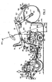
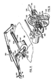
- FIGs. 1 and 2 show a sod laying machine generally indicated at 10.
- the machine 10 includes a rear section 12 supported by rear drive wheels 14, and a front section 16 supported by front drive wheels 18.
- the front and rear sections 16, 12 are connected together by an articulated arrangement shown in Figs. 1, 2 and 3.
- the rear section 12 includes a forwardly projecting hollow tube 20 fixed to and forming part of the frame 22 of the rear section.
- the tube 20 receives a front horizontally extending tube 24 having a retainer plate 26 fixed to its end.
- the front tube 24 is rotatably journaled within a sleeve 28 which is retained in the rear tube by bolts 30, so that the front tube 24 can rotate within the sleeve 28 about the longitudinal axis of the sleeve.
- the first tube 24 is welded to a vertically extending tube 32 which is mounted between top and bottom plates 34, 36 which form part of the frame 38 of the front section 16.
- the vertical tube 32 is retained in position by bolts 40 which extend into cross plates 42 welded into the tube 32.
- Bearings 44 and bearing retaining washers 46 are provided to enable free rotation of the tube 32.
- the operator controls the variable displacement pump 72 by a foot pedal 86.
- the foot pedal 86 is connected by a rod 88 and cable 90 to the lever 73, to pump fluid at a varying rate depending on the extent to which the foot pedal 86 is depressed.
- a boom 94 is provided to lift the sod roll 58.
- the boom 94 includes a pair of forwardly extending boom arms 96, one on each side of the seat 56. Each arm is pivoted at 98 to an upright leg 100 of a U-shaped frame member 102 of the front section 16.
- the boom arms 96 are raised and lowered by a pair of conventional boom lift cylinders 104, one connected between each arm 96 and the plate 36 of the front section 16.
- the operator seat 56 is located between the boom arms 96 and forwardly of upright legs 100, for better viewing of the sod as it unrolls.
- each gripper arm 108 has a bushing 110 welded to its inner side surface near the top thereof.
- the bushing 110 is connected by a pivot shaft 112 to a pair of spaced plates 114 extending downwardly from the lower surface of a C-shaped bracket 116.
- the bracket 116 can slide laterally back and forth across the cross member 106.
- the gripper arms 108 are connected together by a gripper cylinder 124.
- Cylinder 124 has its butt end pivotally secured at 126 to one arm 108 and has its rod end pivotally secured at 128 to the other arm 108.
- the cylinder 124 serves to spread gripper arms 108 apart to receive a sod roll, as shown in full lines in Fig. 6, or to close them to vertically extending positions as shown in dotted lines in Fig. 6, to grip a sod roll.
- the extent to which the gripper arms 108 may close is limited by a stop 129a which is welded to each end bushing 110.
- a stop 129a which is welded to each end bushing 110.
- the upper end of its stop 129a contacts the lower surface of the bracket 116, preventing further movement and allowing the cylinder 124 then to close the other arm 108.
- the gripper arms 108 are prevented from opening too far (e.g. beyond about 20 degrees beyond a vertical position) by engagement of a stop 129b at the upper outer end of each arm 108 against the lower surface of the cross member 106.
- control roller 138 When the sod roll 58 is lifted by the gripper arms 108 and is being unrolled, its rate of rotation is controlled by a control roller 138.
- the control roller 138 extends laterally across the front of the machine 10, is of about the same width as the cross member 106 (so that it will press against the roll of sod no matter where the roll is located laterally) and is held in position by a pair of support arms 140.
- Each support arm 140 is pivotally connected at 142 to the end of its associated boom arm 96.
- the control roller 138 includes a cross shaft 144 pivotally mounted in support arms 140, end disks 146 fixed to the cross shaft 144, and a metal cylinder 148 fixed to the end disks 146.
- the exterior of the control roller 138 has a roughened surface, typically constituted by rubber snow-mobile track 150 having rubber ribs 152.
- Metal cleats 154 are welded to the cylinder 148 and secure the rubber ribs 152 to the control roller 138.
- the control roller 138 includes a sprocket 156 fixed to the cross shaft 144 at one end thereof.
- the sprocket 156 is connected by chain 158 to a drive motor 160 which controls the rotational speed of the control roller 138.
- the hydraulic circuits of the control roller motor 160 and of the wheel drive motors 74, 78 are interconnected as will be explained presently, to improve the operator's control over the sod roll 58 as it is laid.
- the control roller 138 normally is biased against the sod roll 58 by gravity, as shown in Fig. 2. When there is no sod roll in place, the control roller 138 is held clear of the cross member 106, brackets 116 and gripper arms 108 by stops 126.
- the stops 162 project forwardly from and are welded to the downward extensions 105 at the ends of the boom.
- outrigger wheels 170 are provided, mounted on arms 172 pivotally connected at 174 to the front section frame 38.
- Outrigger cylinders 176 are provided to raise and lower the outrigger wheels 170.
- the axis 177 of the outrigger wheels 170 is aligned with the axis 180 of the front wheels 18 in a front to rear direction (as best shown in Fig. 2) so that the outrigger wheels will not scuff newly laid sod when the machine 10 turns a corner.
- the front and rear wheels 18, 14 are arranged in a special configuration. Specifically, the front wheels 18 are spaced apart by lateral gaps 182 and the rear wheels 14 are located behind the gaps 182 and are wider than such gaps. Similarly the rear wheels 14 are spaced apart by a lateral gap 184 and the middle front wheel is located ahead of gap 184 and is wider than such gap. Thus the front and rear wheels together will evenly roll all of the width of the sod which has been laid, to help ensure that the laid sod is properly pressed against the ground.
- the distance D1 between the axis 186 of the rear wheels 14 and the axis of vertical tube 32 is made equal to the distance D2 between the axis of tube 32 and the axis 180 of the front wheels 18.
- the front wheels 18 are all supported on a cross shaft 188 journaled in bearings 190 mounted on the front section frame 38.
- the middle front wheel 18a is mounted on shaft 188 as follows.
- the hub 192 of front wheel 18a is bolted to a housing 194 which encircles shaft 188.
- the sprocket 81 is welded to housing 194 so that the middle wheel 18a turns directly with the sprocket 81.
- a pin 196 extends through housing 194, through shaft 188, and is fixed to the walls of housing 194 so that the housing 194 and shaft 188 turn as a unit.
- the outer two front wheels 18b, 18c are driven as follows.
- Mounted on pin 196 are two planetary gears 198.
- the planetary gears 198 drive a gear 200 fixed to an outer tube 202.
- Outer tube 202 is rotatably mounted on the shaft 188 by bushings 204 for rotation within housing 194 and has a flange 206 welded thereto.
- the flange 206 is bolted to the hub 208 of wheel 18b.
- the planetary gears 198 drive a second gear 210 fixed to a second outer tube 212.
- Tube 212 is rotatably mounted on the shaft 188 by bushings 214 for rotation within housing 194.
- Tube 212 has a flange 216 welded thereto which is bolted to hub 218 of the other outer front wheel 18c.
- the middle front wheel 18a rotates at the speed of sprocket 81 and the outer front wheels 18b, 18c also operate at this speed when the machine is not turning. If the machine turns, the rotation of one of the other front wheels 18b, 18c slows and the rotation of the other front wheel 18b, 18c speeds up to an equal extent.
- This provides a simple and effective single differential for the three front wheels and avoids the need for having two separate differentials (which would be more costly).
- the three way differential prevents scuffing of the newly laid sod when the machine 10 turns.
- a similar differential is provided for the rear wheels 14 and is as follows.
- Driving sprocket 77 is fixed to a rear cross shaft 220 which rotates in bearings 222.
- a pin 224 extends through shaft 220 at its centre and is fixed to the walls of a housing 226.
- the pin 224 carries two planetary gears 228 which drive gears 230, 232.
- Gear 230 is welded to an outer tube 234 which drives rear wheel 14a through a flange 236 and hub 238.
- Gear 232 is welded to an outer tube 240 which drives rear wheel 14b through a flange 242 and hub 224. This provides a simple and inexpensive differential for the rear wheels.
- the machine 10 is operated as follows. The operator will drive the machine to a sod roll 58 to be picked up and will extend the outrigger wheels 170.
- the gripper cylinder 124 is then operated to open the gripper arms 108 to the position shown in Fig. 6, and the machine is maneuvered until the gripper arms 108 straddle the sod roll 58 as shown in Fig. 6.
- the gripper cylinder 124 is then operated to close gripper arms 108 to grip the roll of sod.
- the lateral position of the sod roll 58 can be adjusted before this procedure.
- Two alternative positions of sod roll 58 are shown in Fig. 9.
- the outboard edges 58a, 58b of the sod roll can be moved laterally outwardly of any other part of the machine, so that sod can be laid beside fences, walls and curbs.
- the lateral adjustment is achieved by loosening the hand wheel screw 120 on one gripper arm 108 while leaving the other hand wheel screw 120 firmly in place.
- the gripper cylinder 124 is then extended or retracted to move the one gripper arm laterally to the desired position.
- sod roll 58 is formed with its grass side 250 facing outwardly. This is contrary to the standard in the industry, in which sod is rolled with the grass side facing inwardly (which was thought to protect the sod better against heat and sun).
- the advantage of forming the sod roll as shown is that the area 252 of the sod strip, between the point 254 at which the sod leaves the roll 58 and extending around the bend 256 to the point 258 where the sod contacts the ground, can all be seen by the operator. This is the area in which tears and buckles are usually initiated.
- the operator's eye will normally be located as shown at 260 in Fig.
- the seat 56 is preferably brought even more forwardly and the platform 264 which supports the speed control pedal 86 (and a brake pedal not shown) is preferably arranged to project forwardly of the front wheels 18.
- the horizontal surface of platform 264 is made of open or expanded metal as indicated at 266 in Fig. 1, so the operator can see through it. This improves the operator's view of the important area 252 of the sod.
- sod With its grass side out is unusual, it is believed that such sod will keep as well as or better than sod rolled with the dirt side out. If the grass side dries out, the sod becomes dormant but not necessarily dead, but if the roots dry out, the sod dies.
- the control roller 138 is normally driven at a speed which is synchronized with the ground speed of the machine but which is subject to control by the operator.
- the variable displacement pump 72 is connected through a flow divider 272 to the rear drive motor 74 and to the front drive motor 78.
- the return line 274 from the rear drive motor 74 returns directly to the reservoir 68.
- the return line 276 from the front drive motor 78 extends through a direction control three way valve 278, then back via line 280 to line 274.
- Two conduits 282, 284 extend from three way valve 278 to an auxiliary three way valve 286.
- the direction valve 278 is operated either to the right or to the left to drive the control roller drive motor forwardly or in reverse in synchronism with the front drive motor 78. (Valve 278 is not necessary under some circumstances, if the flow through conduit 276 reverses when hydraulic motor 78 reverses.)
- the control roller drive motor 160 will be operated forwardly.
- the control roller drive motor 160 will be operated in reverse.
- a detent diagrammatically indicated at 288 locks the three way valve 278 in either forward or reverse condition.
- control roller 138 With the mechanism shown, the surface of control roller 138 is arranged to travel at the same speed as the speed at which the machine 10 travels over the ground. If the machine 10 were mechanically rather than hydraulically driven, then a hydraulic pump would be connected to the output of a gearbox of the mechanical drive to obtain a ground drive and will drive the control roller motor 160 again to drive the surface of the control roller 138 at ground speed (and in this case valve 278 would be used since a pump is not normally reversed). Since the control roller 138 acts against the surface of the sod roll 58, the sod is unrolled from the roll 58 at the ground speed of the machine. One might expect that this would in theory be the correct speed to avoid tears and buckles in the sod being laid.
- sod roll at precisely the ground speed of the machine will not always be appropriate, for several reasons. Firstly, the sod tends to stretch as it is being laid, due to its own weight as it hangs down from the roll 58, and this tends to form buckles. The buckles must be removed by braking the roll 58. Secondly, if the front and rear drive wheels lose traction and slip, the unrolling speed will be too high and must be slowed. Thirdly, if the control roller 138 itself slips on the roll of sod, more unrolling speed may be needed.
- a separate hydraulic line 290 from the auxiliary pump 66 is directed to the auxiliary valve 286 and then back through another line 292 to the reservoir 68.
- auxiliary valve 286 When the auxiliary valve 286 is operated in one direction by a lever 294 against a return spring 296, additional pressurized fluid from the pump 66 is directed into the control roller motor 160 in one direction, either to increase its speed if the direction is the same as that in which fluid from the front drive motor 78 is being directed through the control roller motor 160, or to reduce its speed if the directions are opposite.
- the auxiliary valve 286 is operated in the other direction by lever 294 against a return spring 298, the opposite result occurs.
- the sod control roller 138 will operate continuously at a speed corresponding to the ground speed of the machine but with fine control intermittently exerted by the operator.
- sod area 252 In use, as the operator drives the machine forwardly, he or she will watch the sod area 252. If the area 252 becomes too tight, i.e. if the sod begins to form a straight line between the roll 58 and the bottom of front wheels 18, the operator increases the speed of control roller 138 by a series of short pulses or "bumps" of lever 294. Each pulse imparts a momentary speed increase to control roller 138 and adds a short extra length of sod to area 252, to relieve the tension in the sod. Conversely, if a fold or buckle begins to appear in area 252, the operator slows down the speed of control roller 138 by a series of short pulses, to take up the slack. The distance D3 between the rear end of sod roll 58 and the front edge of front wheels 18 is made sufficient not only for adequate visibility of area 252 but also to allow the operator time to react before a tear occurs.
- the operator can readily make fine adjustments in the direction in which the sod roll is facing, because small steering adjustments will pivot the entire front section 16 of the machine, including the boom arms 96.
- Figs. 11 to 13 show a cutoff for use with the sod laying machine previously described.
- sod When sod is being laid, it will be necessary periodically to sever the sod from the roll 58 to begin laying a fresh strip. This can be done using a cutoff indicated at 300 in Figs. 11 to 13.
- the control roller support arms 140 In the version of the machine 10 shown in Figs. 11 to 13, the control roller support arms 140 have a bend 302 therein, to provide clearance for a cutoff saw blade to be described.
- the hydraulic motor 160 has been housed within the control roller cylinder 146 and is therefore not visible.
- the cutoff 300 includes a pair of end plates 304 each pivotably mounted at the end of a control roller support arm 140.
- the pivotal axis of end plates 304 coincides with the axis of control roller 138.
- the end plates 304 carry at their outboard ends a pair of vertically spaced slide bars 306 which extend laterally between the end plates and are fixed thereto.
- Bushings 308 are slideably mounted on the slide bars 306 and are secured to the housing of a hydraulic motor 310.
- the shaft 312 of motor 310 projects toward the control roller and carries a pinion 314 and a saw blade 316.
- the pinion 314 engages a rack 318 which extends between and is fixed to end plates 304.
- the rack 318 has teeth 320 in its upper surface. (The motor, bushings and blade are not shown in Fig. 11 but are shown in Figs. 12 and 13).
- the pinion 314 In use, when the hydraulic motor 310 is operated, the pinion 314 by engaging the rack 318 propels the saw blade 316 laterally across the outer surface of the sod roll 58 (which should be stationary at this time).
- the linear speed at the tips of the teeth of saw blade 316 is much higher than that at the surface of the pinion 314 because of the diameter difference (the pinion is very small while the saw blade may be e.g. 184 mm (7.25 inches) in diameter) so the arrangement cuts the sod effectively and quickly.
- the depth of cut is set as follows.
- An arm 322 is fixed to the housing of the hydraulic motor 310 and extends around the side of saw blade 316 to the front thereof.
- the arm 322 terminates in a vertical bar 324 having a slot 326 therein.
- a depth gauge roller 328 has its shaft pivotably and adjustably mounted in slot 326 by a nut 330. By adjusting the height of roller 328 the depth of cut can be set so that the saw blade 316 will cut through one layer of sod on roll 58. If the cut were to extend slightly into the surface of the next layer, this would not matter so long as the roots and earth in the next layer are not cut.
- the end plates 304 can be raised clear of the sod roll 58 as follows.
- One end plate 304 carries a hook 340 secured thereto.
- a cable 342 is clipped to the hook 340 by a clip 343 and extends over pulleys 344 located at each bend and pivot point in arms 140 and boom arms 96, back to a lever 346 located near the operator seat 56. The operator can thus pull the lever 346 and secure it by a detent 348 to hold the cutoff mechanism 300 away from the sod roll.
- Such slabs are typically 24 inches by 24 inches (610 mm x 610 mm) in North America.
- the circumference of the control roller may be made exactly 610 mm (24 inches), so that one complete turn of the control roller will dispense a 610 mm long slab, and an appropriate mark may be placed on the control roller so that single turns can be observed.
- the forward projection of the sod roll 58 and control roller 138 will prevent the machine from laying sod right up to the wall or fence.
- the measurements of the machine 10 will be such that the length of the strip of sod extending from the cutoff point 358 (Figs. 2, 13) to the ground contact point 258 is approximately equal to the distance from point 258 to the wall or fence when the machine is stopped just short of the wall or fence.
- the length of the sod strip to be severed can be lengthened or decreased by respectively raising or lowering the boom 94 as needed.
- Figs. 14 and 15 show a modification to the machine as described. It is found that in some cases, the edges of rolls of sod held between the gripper arms 108 tend to sag sideways and catch on the gripper arms as the rolls of sod are unrolled. This causes the rolls to jam so that they will not unroll further. It is then necessary to set down the roll of sod, side shift the arms and then pick up the roll of sod again.
- each arm 108' includes a central tube 400 having a block 402 secured to the bottom end thereof by a bolt 404 and nut 406.
- An end plate 408 is welded to the upper end of the tube 400, and the arm 108' continues upwardly from the plate 408 as indicated at 410.
- An outer tube 412 is rotatably mounted on the inner tube 400 by bearings 414.
- the bearings 414 are spaced from the block 402 and the end plate 408 by spacer sleeves 416.
- the cone-shaped support 134 is journaled in the block 402 as shown.
- the tube 412 can rotate, reducing the likelihood that sod from the edge of the roll will catch on the arms 108' and jam the roll.
- the tube 412 can be divided into segments to allow for the fact that the outer periphery of the sod roll 58 is travelling at a higher speed than the inner portion of the roll.
- the plate 422 contains two slots 424 and is secured to block 402 by bolts 426 extending through such slots. This allows the position of the plate 422 to be adjusted so that it can be moved as close as possible to the flange 418, thereby eliminating the undesired pinch effect.
Landscapes
- Life Sciences & Earth Sciences (AREA)
- Environmental Sciences (AREA)
- Road Paving Machines (AREA)
- Protection Of Plants (AREA)
Description
- This invention relates to a machine for laying cut sod from a roll of sod according to the preamble of claim 1, to produce a lawn, and to a method of laying sod.
- Sod harvesting machines have long existed for harvesting sod and forming it into rolls, slabs or the like so that such cut sod may be laid in an appropriate location to produce a lawn. However no commercially successful machines have ever been available to lay the cut sod. Instead the laying operation has always been labour intensive and back breaking. The heavy rolls or slabs of sod are lifted, commonly by hand, to the desired location and are then unrolled and laid as closely as possible against the edge of the previously laid sod. Frequently the sod after being laid must be pushed sideways over the ground to fit tightly against the edge of the adjoining sod. The operation is time consuming and arduous.
- There are numerous difficulties involved in laying sod by machine. Sod is an extremely difficult material with which to work, because it is heavy (due to the layer of earth attached to the roots of the grass) and yet it has very little tensile strength. The tensile strength of the sod can also vary greatly from one sample to another depending on the condition of the sod, such as its thickness, its age, the type of soil, whether it is wet or dry, and even depending on the variety of grass. In addition the characteristics of the sod can vary greatly from one point in a roll of sod to another, e.g. if the roll has been left sitting in which case the top of the roll tends to dry out and the bottom of the roll tends to become more moist. The sod also tends to stretch unevenly when it is being laid, forming unsightly buckles which must be removed, and it may frequently break, interrupting the sod laying operation.
- In addition the locations in which sod must be laid are frequently restricted as to access and limited in space. Further, the sod must commonly be laid up against walls and fences. Therefore a successful sod laying machine should be relatively small and maneuverable and able to lay the fragile sod accurately while reducing the likelihood of breaks and buckles in the sod.
- Accordingly it is an object of the invention to provide a sod laying machine which can lay cut sod from a roll in a controlled manner.
- A sod laying machine is described in US-A-3 982 711, this machine comprising a frame provided with support means in the form of rollers for holding rolls of sod with the axes of the rolls horizontal and perpendicular to the path of travel of the machine. The machine is driven forwardly by means of a tractor vehicle, and as it moves forwardly the rolls of sod are unwound through the agency of conveyor belts and rotary feeding members, which thus pull on the sod to unwind the rolls.
- The machine which forms the subject of the present invention differs from the aforesaid machine in the following respects :-
- (a) the means for driving the machine are mounted on the frame of the machine
- (b) the means for supporting the roll of sod is arranged to support the said roll at its axis of rotation; and
- (c) the drive means for unwinding the roll of sod during travel of the machine is arranged to engage the surface of the roll, and to rotate the roll in a direction such that the top of the roll rotates rearwardly during travel of the machine forwardly, so that the sod will leave the roll at the rear of the roll as the roll unwinds.
- The invention also provides a novel method of laying sod. This comprises
- (a) employing a roll of sod having the grass side of said sod facing outwardly
- (b) suspending said roll of sod at its axis of rotation above the ground,
- (c) carrying said roll of sod forwardly, and
- (d) unwinding said roll of sod with the top of said roll unwinding in a rearward direction, i.e. in a direction generally towards any operator located immediately behind said roll of sod, so that such an operator will have an unobstructed view of the portion of the unwinding sod extending from said roll to said ground.
- Further objects and advantages of the invention will appear from the following description of a preferred embodiment of the invention, taken together with the accompanying drawings in which:
- Fig. 1 is a perspective view of a sod laying machine according to the invention;
- Fig. 2 is a side view of the sod laying machine of Fig. 1 showing the machine laying sod;
- Fig. 3 is a sectional view showing the connection between two portions of the machine of Figs. 1 and 2;
- Fig. 4. is a schematic view showing another alternative method of laying sod;
- Fig. 5 is a side view of the front portion of the sod laying machine of Figs. 1 and 2 in a position in which the machine is prepared to load a roll of sod;
- Fig. 6 is a front sectional view of the gripper arms and sod roll of Fig. 5, taken along lines 8-8 of Fig. 6;
- Fig. 7 is a perspective view of certain portions from Fig. 6;
- Fig. 8 is a side sectional view of a control roller;
- Fig. 9 is a plan view of a portion of the machine of Figs. 1 and 2 showing the layout of the drive wheels;
- Fig. 10 is a schematic view of a portion of the hydraulic circuit for the sod laying machine of Figs. 1 and 2;
- Fig. 11 is a perspective view of a cutoff mechanism for a sod laying machine of the invention;
- Fig. 12 is a perspective view of a portion of the cutoff mechanism of Fig. 11;
- Fig. 13 is a diagrammatic side view showing the cutoff mechanism in two different positions;
- Fig. 14 is a sectional view showing a roller mounted on a support arm of the Fig. 1 machine; and
- Fig. 15 is a perspective view of the arm of Fig. 14.
- Reference is first made to Figs. 1 and 2, which show a sod laying machine generally indicated at 10. The
machine 10 includes arear section 12 supported byrear drive wheels 14, and afront section 16 supported byfront drive wheels 18. - The front and
rear sections rear section 12 includes a forwardly projectinghollow tube 20 fixed to and forming part of theframe 22 of the rear section. Thetube 20 receives a front horizontally extendingtube 24 having aretainer plate 26 fixed to its end. Thefront tube 24 is rotatably journaled within asleeve 28 which is retained in the rear tube bybolts 30, so that thefront tube 24 can rotate within thesleeve 28 about the longitudinal axis of the sleeve. - The
first tube 24 is welded to a vertically extendingtube 32 which is mounted between top andbottom plates frame 38 of thefront section 16. Thevertical tube 32 is retained in position bybolts 40 which extend intocross plates 42 welded into thetube 32.Bearings 44 and bearing retaining washers 46 are provided to enable free rotation of thetube 32. - Steering of the
machine 10 is accomplished by twosteering cylinders 48 having their butt ends 50 pivotally connected at 52 to therear section 12 and having their piston rods pivotally connected at 54 to thefront section 16. Thus when the piston of onesteering cylinder 48 is extended and the piston of the other cylinder is retracted, the front section will be steered relative to the rear section. - The
front tube 24 in thesleeve 28 permits the front and rear sections to pivot about a horizontal axis with respect to each other to allow for ground unevenness. However the extent of the pivoting is limited bystops 55 on therear tube 20 which contact thelower plate 36 on thefront section 16. This prevents undue pivoting, to avoid damage to thesteering cylinders 48. Thepivotal connections stops 55. - The operator of the machine sits in a
seat 56 at the front of the machine, so that he can clearly view the roll of sod 58 (Fig. 2) which the machine is handling and can view the strip ofsod 60 as it leaves theroll 58. Asteering wheel 62 is mounted in front of theseat 56, having asteering valve 64 which is connected by a conventional hydraulic circuit (not shown) to an auxiliaryhydraulic pump 66 andhydraulic reservoir 68. Thepump 66 also powers the other cylinders in the machine, to be described. - The
machine 10 is driven along the ground by a gasoline ordiesel engine 70 which drives a variable displacementhydraulic pump 72 as well as theauxiliary pump 66. Thepump 72 has forward, neutral and reverse built in and operated by asingle lever 73. Thepump 72 operates a rear wheelhydraulic drive motor 74 which is connected by achain 76 and sprocket 77 to therear wheels 14. Thepump 72 also operates a fronthydraulic drive motor 78 which is connected by achain 80 and sprocket 81 to thefront drive wheels 18. The details of the front and rear wheel drives will be described presently. Theengine 70,hydraulic pumps hydraulic reservoir 68, together with afuel tank 82 andbalance weights 84, are all mounted over and to the rear of therear section 12 to counterbalance the weight of theheavy sod roll 58. - The operator controls the
variable displacement pump 72 by afoot pedal 86. Thefoot pedal 86 is connected by arod 88 andcable 90 to thelever 73, to pump fluid at a varying rate depending on the extent to which thefoot pedal 86 is depressed. - The sod handling portion of the
machine 10 will next be described. As shown, aboom 94 is provided to lift thesod roll 58. Theboom 94 includes a pair of forwardly extendingboom arms 96, one on each side of theseat 56. Each arm is pivoted at 98 to anupright leg 100 of aU-shaped frame member 102 of thefront section 16. Theboom arms 96 are raised and lowered by a pair of conventionalboom lift cylinders 104, one connected between eacharm 96 and theplate 36 of thefront section 16. Theoperator seat 56 is located between theboom arms 96 and forwardly ofupright legs 100, for better viewing of the sod as it unrolls. - At their forward ends the
boom arms 96 have shortdownward extensions 105 which are connected together by a fixedcross member 106. Two gripper arms 108 (for gripping the sod roll 58) are slideably mounted on thecross member 106, as best shown in Figs. 1, 6 and 7. As shown in Figs. 6 and 7, eachgripper arm 108 has abushing 110 welded to its inner side surface near the top thereof. Thebushing 110 is connected by apivot shaft 112 to a pair of spacedplates 114 extending downwardly from the lower surface of a C-shapedbracket 116. Thebracket 116 can slide laterally back and forth across thecross member 106. Thecross member 106 includesnotches 118 in its rear edge, and thebracket 116 may be secured over any desirednotch 118 by screwing ahand wheel screw 120 through ahole 122 in thebracket 116 into one of thenotches 118. As will be described, this arrangement allows the side to side position of thegripper arms 108 to be adjusted, which can be helpful when laying sod in restricted areas, and also permits the lateral spacing between thegripper arms 108 to be adjusted depending on the width of the sod being laid. - The
gripper arms 108 are connected together by agripper cylinder 124.Cylinder 124 has its butt end pivotally secured at 126 to onearm 108 and has its rod end pivotally secured at 128 to theother arm 108. Thecylinder 124 serves to spreadgripper arms 108 apart to receive a sod roll, as shown in full lines in Fig. 6, or to close them to vertically extending positions as shown in dotted lines in Fig. 6, to grip a sod roll. - The extent to which the
gripper arms 108 may close is limited by astop 129a which is welded to eachend bushing 110. When one of thearms 108 closes or swings to a vertical position, the upper end of itsstop 129a contacts the lower surface of thebracket 116, preventing further movement and allowing thecylinder 124 then to close theother arm 108. Similarly, thegripper arms 108 are prevented from opening too far (e.g. beyond about 20 degrees beyond a vertical position) by engagement of astop 129b at the upper outer end of eacharm 108 against the lower surface of thecross member 106. - At the end of each
gripper arm 108 there is an inwardly facingdisk 131 pivotally mounted by apivot 132. Protruding inwardly from thedisk 131 is a generally cone-shapedsupport 134. The cone-shapedsupports 134 are adapted to protrude into acardboard tube 136 about which thesod roll 58 has been rolled, in order to grip and lift the roll of sod. Thesupports 134 anddisks 131 rotate with the sod roll. - When the
sod roll 58 is lifted by thegripper arms 108 and is being unrolled, its rate of rotation is controlled by acontrol roller 138. Thecontrol roller 138 extends laterally across the front of themachine 10, is of about the same width as the cross member 106 (so that it will press against the roll of sod no matter where the roll is located laterally) and is held in position by a pair ofsupport arms 140. Eachsupport arm 140 is pivotally connected at 142 to the end of its associatedboom arm 96. - As best shown in Figs. 1 and 8, the
control roller 138 includes across shaft 144 pivotally mounted insupport arms 140,end disks 146 fixed to thecross shaft 144, and ametal cylinder 148 fixed to theend disks 146. The exterior of thecontrol roller 138 has a roughened surface, typically constituted by rubber snow-mobile track 150 havingrubber ribs 152.Metal cleats 154 are welded to thecylinder 148 and secure therubber ribs 152 to thecontrol roller 138. - The
control roller 138 includes asprocket 156 fixed to thecross shaft 144 at one end thereof. Thesprocket 156 is connected bychain 158 to adrive motor 160 which controls the rotational speed of thecontrol roller 138. The hydraulic circuits of thecontrol roller motor 160 and of thewheel drive motors sod roll 58 as it is laid. - The
control roller 138 normally is biased against thesod roll 58 by gravity, as shown in Fig. 2. When there is no sod roll in place, thecontrol roller 138 is held clear of thecross member 106,brackets 116 andgripper arms 108 bystops 126. The stops 162 project forwardly from and are welded to thedownward extensions 105 at the ends of the boom. - To stabilize the machine during sod laying,
outrigger wheels 170 are provided, mounted onarms 172 pivotally connected at 174 to thefront section frame 38.Outrigger cylinders 176 are provided to raise and lower theoutrigger wheels 170. Theaxis 177 of theoutrigger wheels 170 is aligned with theaxis 180 of thefront wheels 18 in a front to rear direction (as best shown in Fig. 2) so that the outrigger wheels will not scuff newly laid sod when themachine 10 turns a corner. - As shown in Fig. 9 the front and
rear wheels front wheels 18 are spaced apart bylateral gaps 182 and therear wheels 14 are located behind thegaps 182 and are wider than such gaps. Similarly therear wheels 14 are spaced apart by a lateral gap 184 and the middle front wheel is located ahead of gap 184 and is wider than such gap. Thus the front and rear wheels together will evenly roll all of the width of the sod which has been laid, to help ensure that the laid sod is properly pressed against the ground. - In addition, as shown in Fig. 9, the distance D1 between the
axis 186 of therear wheels 14 and the axis ofvertical tube 32 is made equal to the distance D2 between the axis oftube 32 and theaxis 180 of thefront wheels 18. This ensures that when the machine turns, the front andrear wheels rear wheels - The
front wheels 18 are all supported on across shaft 188 journaled inbearings 190 mounted on thefront section frame 38. The middlefront wheel 18a is mounted onshaft 188 as follows. Thehub 192 offront wheel 18a is bolted to ahousing 194 which encirclesshaft 188. The sprocket 81 is welded tohousing 194 so that themiddle wheel 18a turns directly with the sprocket 81. Apin 196 extends throughhousing 194, throughshaft 188, and is fixed to the walls ofhousing 194 so that thehousing 194 andshaft 188 turn as a unit. - The outer two
front wheels pin 196 are twoplanetary gears 198. Theplanetary gears 198 drive agear 200 fixed to anouter tube 202.Outer tube 202 is rotatably mounted on theshaft 188 bybushings 204 for rotation withinhousing 194 and has aflange 206 welded thereto. Theflange 206 is bolted to thehub 208 ofwheel 18b. Similarly, theplanetary gears 198 drive asecond gear 210 fixed to a secondouter tube 212.Tube 212 is rotatably mounted on theshaft 188 bybushings 214 for rotation withinhousing 194.Tube 212 has aflange 216 welded thereto which is bolted tohub 218 of the other outerfront wheel 18c. - Thus, the middle
front wheel 18a rotates at the speed of sprocket 81 and the outerfront wheels front wheels front wheel machine 10 turns. - A similar differential is provided for the
rear wheels 14 and is as follows. Driving sprocket 77 is fixed to arear cross shaft 220 which rotates inbearings 222. Apin 224 extends throughshaft 220 at its centre and is fixed to the walls of a housing 226. Thepin 224 carries twoplanetary gears 228 which drive gears 230, 232.Gear 230 is welded to anouter tube 234 which drivesrear wheel 14a through aflange 236 andhub 238.Gear 232 is welded to anouter tube 240 which drivesrear wheel 14b through aflange 242 andhub 224. This provides a simple and inexpensive differential for the rear wheels. - In use the
machine 10 is operated as follows. The operator will drive the machine to asod roll 58 to be picked up and will extend theoutrigger wheels 170. Thegripper cylinder 124 is then operated to open thegripper arms 108 to the position shown in Fig. 6, and the machine is maneuvered until thegripper arms 108 straddle thesod roll 58 as shown in Fig. 6. Thegripper cylinder 124 is then operated to closegripper arms 108 to grip the roll of sod. - If desired, the lateral position of the
sod roll 58 can be adjusted before this procedure. Two alternative positions ofsod roll 58 are shown in Fig. 9. As shown, theoutboard edges hand wheel screw 120 on onegripper arm 108 while leaving the otherhand wheel screw 120 firmly in place. Thegripper cylinder 124 is then extended or retracted to move the one gripper arm laterally to the desired position. - The machine is then driven to the location where sod laying is required, and sod is laid as shown in Fig. 2. As there shown, the
sod roll 58 is formed with itsgrass side 250 facing outwardly. This is contrary to the standard in the industry, in which sod is rolled with the grass side facing inwardly (which was thought to protect the sod better against heat and sun). The advantage of forming the sod roll as shown is that the area 252 of the sod strip, between thepoint 254 at which the sod leaves theroll 58 and extending around thebend 256 to thepoint 258 where the sod contacts the ground, can all be seen by the operator. This is the area in which tears and buckles are usually initiated. The operator's eye will normally be located as shown at 260 in Fig. 2, and it will be seen that there is a direct line ofsight 262 from the operator'seye 260 to the area 252. Thus the operator can react quickly if a tear or buckle begins to occur, to prevent or minimize the occurrence and effect of these events. Even if theboom arms 96 are shortened to bring thesod roll 58 closer to the front of the machine (to improve balance and shorten the machine), the operator can still see all of area 252 by leaning forwardly or looking to the side offoot pedal 86. - Although the operator's
seat 56 has been shown adjacent the front of themachine 10, theseat 56 is preferably brought even more forwardly and theplatform 264 which supports the speed control pedal 86 (and a brake pedal not shown) is preferably arranged to project forwardly of thefront wheels 18. The horizontal surface ofplatform 264 is made of open or expanded metal as indicated at 266 in Fig. 1, so the operator can see through it. This improves the operator's view of the important area 252 of the sod. - Although rolling sod with its grass side out is unusual, it is believed that such sod will keep as well as or better than sod rolled with the dirt side out. If the grass side dries out, the sod becomes dormant but not necessarily dead, but if the roots dry out, the sod dies.
- It will be appreciated that in some cases, it may be desired to drive the
machine 10 in reverse while laying sod. This is depicted in Fig. 4 i.e. the area 252 is not visible to the operator; the operator must choose between watching where the machine is going and watching the sod, and the newly laid sod is not rolled by the machine. Therefore this method of usingmachine 10 will be used only where space limitations so require. However because of the articulated steering, the steering response of the machine is the same whether it is driven forwardly or in reverse, which facilitates laying of the sod while in reverse. - Because of the fragile and widely varying nature of sod, it is found that unrolling from a roll of sod formed with its grass side facing outwardly, and with the top of the roll travelling rearwardly so that the area where the sod leaves the roll can immediately be seen by the operator before anything passes over it, has major advantages over any methods of laying sod previously known to the applicants. However the
machine 10, can if necessary lay sod rolls with the grass side facing inwardly, though this is less desirable. - The
control roller 138 is normally driven at a speed which is synchronized with the ground speed of the machine but which is subject to control by the operator. As shown in the hydraulic circuit of Fig. 10, thevariable displacement pump 72 is connected through aflow divider 272 to therear drive motor 74 and to thefront drive motor 78. Thereturn line 274 from therear drive motor 74 returns directly to thereservoir 68. However thereturn line 276 from thefront drive motor 78 extends through a direction control threeway valve 278, then back vialine 280 toline 274. Twoconduits way valve 278 to an auxiliary threeway valve 286. - The
control roller motor 160 is connected to theconduits - When it is desired to operate the
control roller motor 160 in synchronism with thefront drive motor 78, then thedirection valve 278 is operated either to the right or to the left to drive the control roller drive motor forwardly or in reverse in synchronism with thefront drive motor 78. (Valve 278 is not necessary under some circumstances, if the flow throughconduit 276 reverses whenhydraulic motor 78 reverses.) When the machine is travelling forwardly to lay sod, the controlroller drive motor 160 will be operated forwardly. When the machine is laying sod in reverse, the controlroller drive motor 160 will be operated in reverse. A detent diagrammatically indicated at 288 locks the threeway valve 278 in either forward or reverse condition. - With the mechanism shown, the surface of
control roller 138 is arranged to travel at the same speed as the speed at which themachine 10 travels over the ground. If themachine 10 were mechanically rather than hydraulically driven, then a hydraulic pump would be connected to the output of a gearbox of the mechanical drive to obtain a ground drive and will drive thecontrol roller motor 160 again to drive the surface of thecontrol roller 138 at ground speed (and in thiscase valve 278 would be used since a pump is not normally reversed). Since thecontrol roller 138 acts against the surface of thesod roll 58, the sod is unrolled from theroll 58 at the ground speed of the machine. One might expect that this would in theory be the correct speed to avoid tears and buckles in the sod being laid. - However driving the sod roll at precisely the ground speed of the machine will not always be appropriate, for several reasons. Firstly, the sod tends to stretch as it is being laid, due to its own weight as it hangs down from the
roll 58, and this tends to form buckles. The buckles must be removed by braking theroll 58. Secondly, if the front and rear drive wheels lose traction and slip, the unrolling speed will be too high and must be slowed. Thirdly, if thecontrol roller 138 itself slips on the roll of sod, more unrolling speed may be needed. - Therefore a separate
hydraulic line 290 from theauxiliary pump 66 is directed to theauxiliary valve 286 and then back through anotherline 292 to thereservoir 68. When theauxiliary valve 286 is operated in one direction by alever 294 against areturn spring 296, additional pressurized fluid from thepump 66 is directed into thecontrol roller motor 160 in one direction, either to increase its speed if the direction is the same as that in which fluid from thefront drive motor 78 is being directed through thecontrol roller motor 160, or to reduce its speed if the directions are opposite. When theauxiliary valve 286 is operated in the other direction bylever 294 against a return spring 298, the opposite result occurs. Thus thesod control roller 138 will operate continuously at a speed corresponding to the ground speed of the machine but with fine control intermittently exerted by the operator. - In use, as the operator drives the machine forwardly, he or she will watch the sod area 252. If the area 252 becomes too tight, i.e. if the sod begins to form a straight line between the
roll 58 and the bottom offront wheels 18, the operator increases the speed ofcontrol roller 138 by a series of short pulses or "bumps" oflever 294. Each pulse imparts a momentary speed increase to controlroller 138 and adds a short extra length of sod to area 252, to relieve the tension in the sod. Conversely, if a fold or buckle begins to appear in area 252, the operator slows down the speed ofcontrol roller 138 by a series of short pulses, to take up the slack. The distance D3 between the rear end ofsod roll 58 and the front edge offront wheels 18 is made sufficient not only for adequate visibility of area 252 but also to allow the operator time to react before a tear occurs. - Because of the articulated steering, the operator can readily make fine adjustments in the direction in which the sod roll is facing, because small steering adjustments will pivot the
entire front section 16 of the machine, including theboom arms 96. - Although a simple control roller has been shown to control the
sod roll 58, if desired a roller with flats on it could be used, or even a conveyor having an appropriate drive. However a simple round roller is preferred because of its compactness and low cost. - Reference is next made to Figs. 11 to 13 which show a cutoff for use with the sod laying machine previously described. When sod is being laid, it will be necessary periodically to sever the sod from the
roll 58 to begin laying a fresh strip. This can be done using a cutoff indicated at 300 in Figs. 11 to 13. In the version of themachine 10 shown in Figs. 11 to 13, the controlroller support arms 140 have abend 302 therein, to provide clearance for a cutoff saw blade to be described. In addition thehydraulic motor 160 has been housed within thecontrol roller cylinder 146 and is therefore not visible. - The
cutoff 300 includes a pair ofend plates 304 each pivotably mounted at the end of a controlroller support arm 140. The pivotal axis ofend plates 304 coincides with the axis ofcontrol roller 138. Theend plates 304 carry at their outboard ends a pair of vertically spaced slide bars 306 which extend laterally between the end plates and are fixed thereto.Bushings 308 are slideably mounted on the slide bars 306 and are secured to the housing of ahydraulic motor 310. Theshaft 312 ofmotor 310 projects toward the control roller and carries apinion 314 and asaw blade 316. Thepinion 314 engages arack 318 which extends between and is fixed to endplates 304. Therack 318 hasteeth 320 in its upper surface. (The motor, bushings and blade are not shown in Fig. 11 but are shown in Figs. 12 and 13). - In use, when the
hydraulic motor 310 is operated, thepinion 314 by engaging therack 318 propels thesaw blade 316 laterally across the outer surface of the sod roll 58 (which should be stationary at this time). The linear speed at the tips of the teeth ofsaw blade 316 is much higher than that at the surface of thepinion 314 because of the diameter difference (the pinion is very small while the saw blade may be e.g. 184 mm (7.25 inches) in diameter) so the arrangement cuts the sod effectively and quickly. - The depth of cut is set as follows. An
arm 322 is fixed to the housing of thehydraulic motor 310 and extends around the side ofsaw blade 316 to the front thereof. Thearm 322 terminates in avertical bar 324 having aslot 326 therein. Adepth gauge roller 328 has its shaft pivotably and adjustably mounted inslot 326 by anut 330. By adjusting the height ofroller 328 the depth of cut can be set so that thesaw blade 316 will cut through one layer of sod onroll 58. If the cut were to extend slightly into the surface of the next layer, this would not matter so long as the roots and earth in the next layer are not cut. - The
end plates 304 can be raised clear of thesod roll 58 as follows. Oneend plate 304 carries a hook 340 secured thereto. Acable 342 is clipped to the hook 340 by aclip 343 and extends overpulleys 344 located at each bend and pivot point inarms 140 and boomarms 96, back to alever 346 located near theoperator seat 56. The operator can thus pull thelever 346 and secure it by adetent 348 to hold thecutoff mechanism 300 away from the sod roll. - If the direction of unrolling of the sod roll is reversed, then the cutoff can also be reversed by unclipping the
clip 343. Theentire cutoff 300 is then swung beneath thecontrol roller 138 as indicated byarrow 350 in Fig. 13, to the position shown in dotted lines in Fig. 13. (The sod roll will be removed during this procedure). Thecable 342 is then clipped to asecond hook 352 on the other side ofend plate 304. A second depth gauge roller may be provided to control the depth of cut in this orientation, or alternativelyroller 328 may be loosened and moved inslot 326 to the required new position. Thus the same cutoff can be used whether the sod roll is being unwound in a clockwise or counter-clockwise direction. - The cutoff may be on the side of the sod roll where the sod is travelling downwardly, so that the sod in the roll will not fall backwardly. Alternatively the cutoff may be on the side of the
roll 58 where the sod is travelling upwardly, as shown in Fig. 13 wherearrow 354 indicates the direction of rotation of the sod roll. In this case thecontrol roller 138 holds the flap ofsod 356 which is located clockwise (as drawn) of theblade 316 and prevents such flap from falling backwardly. - In some cases it will be desired to dispense sod slabs from the roll. Such slabs are typically 24 inches by 24 inches (610 mm x 610 mm) in North America. In that case the circumference of the control roller may be made exactly 610 mm (24 inches), so that one complete turn of the control roller will dispense a 610 mm long slab, and an appropriate mark may be placed on the control roller so that single turns can be observed.
- When the
machine 10 while laying sod is to be driven forwardly up to a wall or fence, the forward projection of thesod roll 58 andcontrol roller 138 will prevent the machine from laying sod right up to the wall or fence. However typically the measurements of themachine 10 will be such that the length of the strip of sod extending from the cutoff point 358 (Figs. 2, 13) to theground contact point 258 is approximately equal to the distance frompoint 258 to the wall or fence when the machine is stopped just short of the wall or fence. Thus, when the sod is cut, the cut strip will fall to the ground and can then be laid with little waste. The length of the sod strip to be severed can be lengthened or decreased by respectively raising or lowering theboom 94 as needed. - Reference is next made to Figs. 14 and 15, which show a modification to the machine as described. It is found that in some cases, the edges of rolls of sod held between the
gripper arms 108 tend to sag sideways and catch on the gripper arms as the rolls of sod are unrolled. This causes the rolls to jam so that they will not unroll further. It is then necessary to set down the roll of sod, side shift the arms and then pick up the roll of sod again. - To avoid this time consuming difficulty, the lower portions of the
gripper arms 108 may be fabricated as indicated at 108' in Figs. 14 and 15. As shown, each arm 108' includes acentral tube 400 having ablock 402 secured to the bottom end thereof by abolt 404 andnut 406. Anend plate 408 is welded to the upper end of thetube 400, and the arm 108' continues upwardly from theplate 408 as indicated at 410. - An
outer tube 412 is rotatably mounted on theinner tube 400 bybearings 414. Thebearings 414 are spaced from theblock 402 and theend plate 408 byspacer sleeves 416. The cone-shapedsupport 134 is journaled in theblock 402 as shown. - With the arrangement shown, when the roll of sod indicated in dotted lines at 58 rotates past the
outer tube 412, thetube 412 can rotate, reducing the likelihood that sod from the edge of the roll will catch on the arms 108' and jam the roll. Although only a singleouter tube 412 has been shown, if desired thetube 412 can be divided into segments to allow for the fact that the outer periphery of thesod roll 58 is travelling at a higher speed than the inner portion of the roll. - It is further found that where the
outer tube 412 meets theflange 418 of the cone-shapedsupport 134, i.e. atpoint 420, a pinch effect occurs. In other words, atpoint 420 theflange 418, which is rotating in the direction of arrow X, meets the tube orroller 412, which is rotating in the direction of arrow Y. Sod engaging the two rotating surfaces at this point tends to be pinched between them, again jamming theroll 58 and preventing it from turning. To prevent this aguard plate 422 is provided.Plate 422 covers the front surface and inside front half of the surface of the lower portion oftube 412, wheretube 412 meetsflange 418. Theplate 422 contains two slots 424 and is secured to block 402 bybolts 426 extending through such slots. This allows the position of theplate 422 to be adjusted so that it can be moved as close as possible to theflange 418, thereby eliminating the undesired pinch effect. - If the
sod roll 58 is to be driven opposite to the direction of arrow X to any substantial extent, then a similar guard plate can be placed on the rear surface ofblock 402. - Reference numerals have been added to the claims to comply with the Regulations of the European Patent Convention as interpreted by the European Patent Office. The inclusion of these numerals is not intended to restrict the scope of the claims and should not be regarded as having this effect.
Claims (35)
- A sod laying machine (10) comprising a frame (22,38), means (70,72,74,76,77,78,80,81) for driving the machine forwardly along a path of travel, means (48,62,64,66) for steering the machine, support means (94,96,108,134) mounted on said frame (38) for supporting a roll of sod (58) above the ground with the axis of the roll horizontal and perpendicular to said path of travel, and drive means (138,158,160) for unwinding the roll of sod (58) during travel of the machine (10)
characterized in that(a) the means (70,72,74,76,77,78,80,81) for driving the machine are mounted on said frame (22,38)(b) the support means (94,96,108,134) is arranged to support the roll of sod (58) at its axis of rotation; and(c) the drive means (138,158,160) is arranged to engage the surface of the roll of sod (58) for power unwinding the roll during travel of the machine, and to rotate the roll (58) in a direction such that the top of the roll rotates rearwardly during travel of the machine forwardly, so that the sod (60) will leave the roll (58) at the rear of the roll as the roll unwinds. - A machine according to claim 1 wherein said drive means (138, 158, 160) comprises an elongated substantially round roller (183) having its axis parallel to that of said roll of sod.
- A machine according to claim 1 wherein said support means (94, 96, 108, 134) comprise a pair of gripper arms (108), each of said gripper arms (108) being adapted to engage one end of said roll (58), means (124) for moving each of said arms (108) inwardly toward each other to grip a roll of sod (58) and outwardly away from each other to release said roll of sod (58), and stop means (129a) associated with each arm (108) to prevent each arm (108) from moving inwardly beyond a vertical position toward the other arm.
- A machine according to claim 3 wherein said support means (94, 96, 108, 134) include a boom (94), said boom (94) having a pair of boom arms (96) extending over one end of said machine and having free ends (105), and a cross member (106) extending between said free ends, said gripper arms (108) being mounted on said cross member (106), said stop means (129a) being mounted on said gripper arms.
- A machine according to claim 1 wherein said machine has a front end, said support means (94, 96, 108, 134) including a boom (94), said boom (94) having a pair of boom arms (96) extending over said front end, said machine including an operator's seat (56) at said front end of said machine between said boom arms (96), said seat (56) facing forwardly and being positioned for an operator in said seat to have a straight line of sight view (262) of sod (60) travelling in the air from said roll (58) as said sod contacts the ground.
- A machine according to claim 5 wherein said frame includes a front section (16) and a rear section (12), said operator seat (56) and said boom (94) being on said front section (16), means (20, 24, 32) connecting said front and rear sections (16, 12) together and having a vertical pivot axis for pivoting of said front and rear sections (16, 12) relative to each other about said vertical axis, said means (48, 62, 64, 66) for steering comprising hydraulic steering means (48, 64, 66) for pivoting said front and rear sections (16, 12) relative to each other.
- A machine according to claim 6 and further including an engine (70), a hydraulic pump (66, 72), a fuel tank (82) and a hydraulic fluid reservoir (68) all located on said rear section (12) to counterbalance said front section (16).
- A machine according to any of claims 1 to 7 and including a plurality of front wheels (18) laterally spaced apart to define at least one front gap (182) therebetween, and a plurality of rear wheels (14) laterally spaced apart to define at least one rear gap (184) therebetween, a rear wheel (14) being aligned with each of said front gaps (182) and a front wheel (18) being aligned with each of said rear gaps (184) so that said front and rear wheels (182, 184) together will roll the entire width of said sod (60) being laid.
- A machine according to claim 8 and comprising a front section (16) supported on said front wheels (18) and a rear section (12) supported on said rear wheels (14), said front wheels (18) having a common transverse front axis (180) and said rear wheels (14) having a common transverse rear axis (186), means (20, 24, 32) connecting said front and rear sections (16, 12) together and having a vertical pivot axis for pivoting of said front and rear sections (16, 12) relative to each other for steering of said machine, the distances (D1, D2) between said vertical pivot axis and each of said front and rear axes (180, 186) being substantially the same.
- A machine according to claim 1 wherein said drive means (138, 158, 160) includes first means (160, 276, 278, 280) for normally driving the surface of said roll of sod (58) at the ground speed of said machine, and second means (66, 284, 286, 290, 292) for superimposing on the speed normally imparted to said roll (58) by said first means (160, 276, 278, 280), either an increase or a decrease in the speed of the surface of said roll of sod (58), and operator actuator means (294) operable by an operator of said machine for manually operating said second means (66, 284, 286, 290, 292).
- A machine according to claim 10 wherein said drive means (138, 158, 160) includes a drive roller (138) for engaging the surface of said roll of sod.
- A machine according to claim 11 wherein said first means (160, 276, 278, 280) includes a hydraulic motor (160) connected to said drive roller (138) to drive the latter, and first hydraulic circuit means (276, 278, 280) responsive to the ground speed of said machine for driving said hydraulic motor (160), and said second means (66, 284, 286, 290, 292) comprises a hydraulic pump (66), second hydraulic circuit means (66, 284, 286, 290; 292) connecting said pump (66) to said hydraulic motor (160), said operator actuator means (294) being connected to said second hydraulic circuit means (66, 284, 286, 290, 292) for operating said second hydraulic circuit means (66, 284, 286, 290, 292) for selectively increasing or decreasing the speed of said hydraulic motor (160).
- A sod laying machine (10) according to claim 1 and having a front end, an operator's seat (56) at said front end of said machine, said support means (94, 96, 108, 134) comprising a boom (94) projecting over said front end of said machine for suspending a roll of sod (58) in the air above the ground in a position spaced from said front end so that an operator in said seat (56) may see the sod (60) travelling in the air from said roll (58) to the ground before it passes beneath the machine.
- A machine according to claim 13 wherein said drive means (138, 158, 160) comprises roller means (138) for engaging the surface of said roll of sod (58).
- A machine according to claim 14 wherein said drive means (138, 158, 160) includes first means (160, 276, 278, 280) for normally driving the surface of said roll (58) at the ground speed of said machine, and second means (66, 284, 286, 290, 292) for superimposing, on the speed normally imparted to said roll (58) by said first means (160, 276, 278, 280), either an increase or a decrease in the speed of the surface of said roll of sod (58), and operator actuator means (294) operable by an operator of said machine for manually operating said second means (66, 284, 286, 290, 292).
- A machine according to claim 14 and having wheels (14, 18) adapted to support said machine and to roll the entire width of said strip of sod.
- A sod laying machine according to any of claims 1 to 16 and including cutoff means (300) connected to said support means (96) for severing a strip of sod from the surface of said roll of sod (58), said cutoff means (300) comprising a cutter (310) having a cutting blade (316) oriented in a plane perpendicular to said path of travel, means (306, 308) positioning and supporting said cutting blade (316) for transverse movement across the surface of said roll of sod (58) one side thereof to the other, means (314, 318) for moving said cutting blade across said roll of sod to form a transverse cut therein, and depth gauge means (328) for limiting the depth of penetration of said roll of sod (58) by said cutting blade (316) to substantially the thickness of a single layer of sod.
- A sod laying machine according to claim 17 wherein said cutting blade (316) is a saw-toothed disk, said cutter (310) including means (312) for rotating said cutting blade.
- A machine according to any of claims 1 to 18 and including a roll of sod (58) suspended by said support means (94, 96, 108, 134), the sod (60) of said roll (58) having its grass side facing outwardly.
- A machine according to claim 5 and including a platform (264) below said seat (56) for supporting the feet of said operator, said platform being made of an open grid material (266) so that said line of sight (262) may extend therethrough.
- A sod laying machine according to claim 9 and including means (188, 190, 192, 194, 196, 198, 200, 202, 204, 206, 208, 210, 212, 214, 216, 218) connecting said front wheels (18) to each other for permitting each front wheel (18) to rotate at a different speed from the other front wheels (18) as said machine turns a corner, and means (77, 220, 222, 224, 226, 228, 230, 232, 234, 236, 238, 240) connecting said rear wheels (14) to each other for permitting each rear wheel (14) to rotate at a different speed from the other rear wheels (14) as said machine turns said corner so that said machine may roll without gaps sod (60) laid by said machine with a reduced likelihood of scuffing of such laid sod (60) by said wheels (14, 18).
- A machine according to claim 21 wherein said means for driving said machine forwardly (70, 72, 74, 76, 77, 78, 80, 81) is coupled to all of said front and rear wheels (18, 14) for driving all said wheels.
- A machine according to claim 21 or 22 including a pair of front outrigger wheels (170), and means (176) for lowering said outrigger wheels (170) into ground engaging position and for raising said outrigger wheels (170) to a storage position, said outrigger wheels (170) being positioned so that when they are in said ground engaging position, they have a common axis which is transverse to said path of travel and coincident in a front to rear direction with the axis (180) of said front wheels (18).
- A machine according to claim 9, 21 or 22 wherein said means (20, 24, 32) connecting said front and rear sections (16, 22) together includes pivot means (20, 24) having a horizontal axis substantially aligned with said path of travel for pivoting of said front and rear sections (16, 12) relative to each other about said horizontal axis.
- A machine according to claim 1 or 13 wherein said support means (94, 96, 108, 134) comprise a pair of gripper arms (108), each of said gripper arms (108) being adapted to engage each end of said roll (58), and means (124) for moving said arms (108) inwardly toward each other to grip a roll of sod and outwardly away from each other to release said roll of sod (58).
- A machine according to claim 5 or 25 wherein each gripper arm (108') includes roller means (412) extending longitudinally along said arm (108') to reduce jamming of the sides of said roll of sod (58) on said gripper arms (108').
- A machine according to claim 1 or 13 wherein said support means comprise a pair of elongated gripper arms (108'), each arm having a longitudinal axis and being adapted to engage one end of said roll (58), and means (124) for moving said arms (108') inwardly toward each other to grip a roll of sod (58) and outwardly away from each other to release said roll of sod (58), and wherein each gripper arm (108') includes roller means (412) mounted thereon, said roller means having an axis of rotation parallel to the longitudinal axis of said arm (108') on which it is mounted and having a rotatable roller surface facing inwardly toward the other arm (108'), said roller means (412) being elongated in the direction of its axis and extending longitudinally along said arm (108') to reduce jamming of the sides of said roll of sod (58) on said gripper arms (108').
- A machine according to claim 1 or 13 wherein each gripper arm (108') includes at the end thereof a laterally inwardly projecting support (134) adapted to extend into said roll of sod (58), said support (134) being rotatably mounted at the end of said gripper arm (108'), said support (134) including an enlarged flange (418) adjacent said gripper arm (108'), said gripper arm (108') further including a guard plate (422) extending over said roller means (412) adjacent said flange (418) to reduce pinching of said sod between said roller means (412) and said flange (418).
- A method of laying sod comprising:(a) employing a roll of sod (58) having the grass side (250) of said sod (58) facing outwardly,(b) suspending said roll of sod (58) above the ground at its axis of rotation.(c) carrying said roll of sod (58) forwardly, and(d) unwinding said roll of sod (58) with the top of said roll unwinding in a rearward direction i.e. in a direction generally towards any operator located immediately behind said roll of sod (58), so that such an operator will have an unobstructed view of the portion (252) of the unwinding sod (60) extending from said roll (58) to said ground.
- A method according to claim 29 and including the step of driving said roll of sod (58) at a controlled rotational speed thus to reduce the likelihood of buckles and tears in the sod being laid.
- A method according to claim 30 and including the steps of normally driving the surface of said roll of sod (58) at a speed equal to the speed at which said roll of sod is carried forwardly, and making momentary adjustments in the speed at which the surface of said roll of sod (58) is driven to relieve tension in said unwinding sod (60) or to take up slack in said unwinding sod (60).
- A method according to claim 29 and including the step of rolling said sod (60) after said sod (60) has been laid, said rolling occurring at a position located rearwardly of said roll (58) and closely spaced from said roll (58).
- A method according to claim 30 and including the step of severing sod in said roll (58).
- A method according to claim 30 wherein said sod is severed at a location in said roll (58) where said sod is travelling upwardly in said roll, and including the step of holding the flap (356) of remaining sod in said roll from falling downwardly.
- A method according to claim 30 wherein said sod is advanced toward a barrier and is severed at a first location (358) in said roll (58) such that when said roll (58) is stopped adjacent said barrier, the length of sod extending from said first location (358) to a second location where the sod first contacts the ground prior to severing is approximately equal to the distance between said second location and said barrier.
Applications Claiming Priority (2)
| Application Number | Priority Date | Filing Date | Title |
|---|---|---|---|
| CA463424 | 1984-09-17 | ||
| CA000463424A CA1243550A (en) | 1984-09-17 | 1984-09-17 | Sod laying machine and method |
Publications (3)
| Publication Number | Publication Date |
|---|---|
| EP0178081A2 EP0178081A2 (en) | 1986-04-16 |
| EP0178081A3 EP0178081A3 (en) | 1987-07-29 |
| EP0178081B1 true EP0178081B1 (en) | 1991-05-15 |
Family
ID=4128736
Family Applications (1)
| Application Number | Title | Priority Date | Filing Date |
|---|---|---|---|
| EP19850306547 Expired - Lifetime EP0178081B1 (en) | 1984-09-17 | 1985-09-16 | Sod laying machine and method |
Country Status (5)
| Country | Link |
|---|---|
| US (3) | US4754815A (en) |
| EP (1) | EP0178081B1 (en) |
| AU (1) | AU590727B2 (en) |
| CA (3) | CA1267324A (en) |
| DE (1) | DE3582847D1 (en) |
Families Citing this family (55)
| Publication number | Priority date | Publication date | Assignee | Title |
|---|---|---|---|---|
| DE69006671T2 (en) * | 1989-09-29 | 1994-09-22 | Turfgrass Services Int | Device for processing turf. |
| US5234284A (en) * | 1991-11-04 | 1993-08-10 | Kabushiki Kaisha Komatsu Seisakusho | Wheeled road surface cutter |
| US5215278A (en) * | 1991-12-02 | 1993-06-01 | Hess Douglas S | Apparatus for laying turf |
| US5247787A (en) * | 1992-01-22 | 1993-09-28 | Snell Lloyd D | Multi-purpose orchard shaker/power plant |
| US5169048A (en) * | 1992-02-05 | 1992-12-08 | Himebaugh Forrest K | Shingling apparatus |
| US5316427A (en) * | 1992-04-03 | 1994-05-31 | Delong Leonard D | Round bale unroller and method |
| FR2695534B1 (en) * | 1992-09-11 | 1994-12-30 | Sodiape | Grass laying machine. |
| FR2697550B1 (en) * | 1992-11-02 | 1995-01-20 | Yn | Machine for draining grassy or stabilized ground. |
| GB9224431D0 (en) * | 1992-11-21 | 1993-01-13 | Rolawn Limited | Turf laying apparatus |
| US5304014A (en) * | 1993-02-25 | 1994-04-19 | Jmw Welding & Manufacturing, Inc. | Apparatus for laying out and taking up a long length, wide width flexible sheeting |
| US5307880A (en) * | 1993-03-12 | 1994-05-03 | Woerner Edward E | Sod roll-out machine with endless tracks |
| IT1278028B1 (en) * | 1995-02-23 | 1997-11-17 | Ind Meccanica F Lli Tortella S | COMBINED AGRICULTURAL MACHINE THAT MAKES THE ENTIRE RANGE OF SEEDING OPERATIONS IN ONE STEP |
| US5651241A (en) * | 1995-10-11 | 1997-07-29 | Ransomes America Corporation | Walk-behind mower controls with dual function control bracket |
| US5697452A (en) * | 1995-12-05 | 1997-12-16 | American Roller Bushing Corporation | Sod roll laying apparatus and method |
| US5806445A (en) * | 1996-03-08 | 1998-09-15 | Buckeye Bluegrass Farms, Inc. | Liquid mulch apparatus for manufacturing sods |
| US5865258A (en) * | 1997-01-13 | 1999-02-02 | Mcgrew, Ii; Jeff | Golf course maintenance machine |
| US5988289A (en) * | 1997-08-04 | 1999-11-23 | Holland; Gregory Paul | Sod laying apparatus |
| US6131668A (en) * | 1997-12-29 | 2000-10-17 | Clark Equipment Company | Sod laying apparatus and method |
| US6213218B1 (en) * | 1998-10-22 | 2001-04-10 | Donald R. Miller | Sod laying apparatus |
| US6112680A (en) * | 1998-10-30 | 2000-09-05 | Hummer Sport Surfaces, L.L.C. | Grass turf tile lifting device and method |
| US6263774B1 (en) * | 1999-01-07 | 2001-07-24 | Jerome S. Rogness | Apparatus and method for cutting twine wound about a bale |
| US6179060B1 (en) | 1999-05-25 | 2001-01-30 | Thomas E. Halter | Sod-laying vehicle apparatus and Sod-holding device therefor |
| US6299094B1 (en) * | 1999-09-16 | 2001-10-09 | Forrest Hood James, Jr. | Apparatus for applying and retrieving protective ground coverings |
| US6575393B1 (en) | 1999-09-16 | 2003-06-10 | Forrest Hood James, Jr. | Apparatus for applying and retrieving protective ground coverings |
| CA2307926C (en) * | 2000-05-09 | 2002-06-11 | Degelman Industries Lp | Multi-functional self-propelled farm tractor |
| US6364027B1 (en) * | 2000-06-26 | 2002-04-02 | Donald Tvetene | Sod harvester |
| US6550406B2 (en) | 2001-03-21 | 2003-04-22 | Anthony C. Bass | Sod roll installation device |
| US7673697B2 (en) | 2002-01-23 | 2010-03-09 | Jonathan Michael Peterson | Sod laying machine |
| US6663324B2 (en) | 2002-04-18 | 2003-12-16 | Thomas H. Nordloh | Erosion blanket installation device |
| US6764039B1 (en) | 2003-03-04 | 2004-07-20 | Forrest Hood James, Jr. | Apparatus for rapidly laying, retrieving, and securing ground covers |
| US20040187469A1 (en) * | 2003-03-11 | 2004-09-30 | Price Richard G. | Hay spreading apparatus |
| US20050167540A1 (en) * | 2004-01-09 | 2005-08-04 | M J K Turf Contractors, Inc. | Apparatus for laying a length of material on a surface |
| US7188447B2 (en) * | 2004-03-15 | 2007-03-13 | Sherron & Rose, Llc | Machine for laying ground cover on seeded areas |
| US7350738B1 (en) | 2005-08-25 | 2008-04-01 | Himmelberg Wayne F | Sod unrolling machine |
| MX2009004977A (en) * | 2006-11-17 | 2009-11-02 | G2 Turftools Inc | Rolled turf layer. |
| US7740083B2 (en) * | 2007-07-23 | 2010-06-22 | Trebro Holding Co., Inc. | Sod harvesting apparatus |
| US7694772B1 (en) * | 2007-08-03 | 2010-04-13 | M-B Companies Inc. | Forward cab articulated tractor |
| US8555762B1 (en) | 2009-04-29 | 2013-10-15 | John Christopher Jones | Saw stop |
| US8974311B2 (en) * | 2010-08-10 | 2015-03-10 | Technology Licensing Corp. | Method and device for installing synthetic turf |
| US8656694B2 (en) * | 2011-01-12 | 2014-02-25 | Agco Corporation | Auxiliary drive motor for hay conditioner on a windrower header |
| US20130277488A1 (en) * | 2012-04-19 | 2013-10-24 | Paul Hovland | Hydraulically Actuated Drain Tile Roll Loading and Support Assembly |
| US11044844B2 (en) * | 2012-06-15 | 2021-06-29 | Mauno Keski-Luopa | Maintenance and transportation method, system, and apparatus |
| US9848532B2 (en) * | 2012-06-15 | 2017-12-26 | Mauno Keski-Luopa | Modular lawn maintenance machine and method |
| US8813861B2 (en) * | 2012-11-13 | 2014-08-26 | 1093929 Ontario Limited | Flap and roll positioner for a sod harvesting apparatus |
| US9908264B2 (en) * | 2013-12-16 | 2018-03-06 | Re-Gen Enterprises, Llc | Methods and apparatus for recycling deployed sheet material |
| US8794342B1 (en) * | 2014-04-01 | 2014-08-05 | O2 Turftools, Inc. | Turf seamer |
| US10125463B2 (en) | 2014-10-16 | 2018-11-13 | Heavy Metals, Inc. | Method and apparatus for real-time adjustment of the size and drainage tile capacity of drainage tile spools and for utilizing the same |
| US10532902B2 (en) | 2016-04-29 | 2020-01-14 | Motz Enterprises, Inc. | System and method for rolling up a flexible sheet |
| US10934118B1 (en) * | 2017-08-09 | 2021-03-02 | Joseph W. Bates, III | Assembly for dispensing sheeting from a roll |
| CN114667892A (en) * | 2022-05-30 | 2022-06-28 | 潍坊科技学院 | Garden turf laying embedding equipment |
| CN114868489B (en) * | 2022-06-23 | 2023-09-05 | 上海工程技术大学 | Be applied to ecological remediation's intelligent vegetation restoration multifunctional machinery car |
| US12158004B2 (en) | 2022-07-12 | 2024-12-03 | Renovate Robotics, Inc. | Devices configured to operate on an angled surface, and associated systems and methods |
| CN115226574B (en) * | 2022-07-28 | 2024-05-28 | 西安理工大学 | Multifunctional grass grid laying device |
| CN115250838B (en) * | 2022-09-01 | 2023-09-29 | 上海市园林设计研究总院有限公司 | Park green land transformation auxiliary device |
| CN115633602B (en) * | 2022-11-30 | 2024-04-19 | 陕西中泾渭达水利工程设计有限公司 | Device and method for paving turf in soil and water conservation engineering |
Family Cites Families (27)
| Publication number | Priority date | Publication date | Assignee | Title |
|---|---|---|---|---|
| US1687928A (en) * | 1925-11-13 | 1928-10-16 | Fisk Rubber Co | Automatic cutting device |
| US2427611A (en) * | 1942-12-21 | 1947-09-16 | Rca Corp | Sheet severing means |
| US2617347A (en) * | 1949-04-06 | 1952-11-11 | Provost Henri | Forwardly mounted tractor sod cutter |
| US3429377A (en) * | 1965-03-05 | 1969-02-25 | John F Nunes Jr | Sod harvesting apparatus |
| US3519082A (en) * | 1967-02-27 | 1970-07-07 | William W Miner | Automatic sod harvester |
| US3473755A (en) * | 1968-07-15 | 1969-10-21 | Brown & Brown Inc | Automatic laying and retrieving ground cover apparatus |
| US3632054A (en) * | 1969-10-15 | 1972-01-04 | Arnold A Heppelmann | Wire mesh dispensing apparatus and method |
| US3809262A (en) * | 1971-10-15 | 1974-05-07 | A Galis | Self-propelled haulage vehicle |
| US3931940A (en) * | 1974-05-10 | 1976-01-13 | Chromalloy American Corporation | Carpet feeding, measuring and rolling apparatus |
| US4025006A (en) * | 1974-06-05 | 1977-05-24 | Turnbow Carrol E | Apparatus for dispensing hay from large round bales |
| US3968940A (en) * | 1974-07-10 | 1976-07-13 | Godbersen Byron L | Apparatus for handling bales |
| US3937345A (en) * | 1974-11-15 | 1976-02-10 | Wagner Mining Equipment, Inc. | Shovel loader with ejector bucket |
| US3982711A (en) * | 1975-04-09 | 1976-09-28 | Bradley Frank M | Sod laying machine |
| US4067393A (en) * | 1975-08-05 | 1978-01-10 | Szarkowski Raphael J | Method and apparatus for handling and laying strips of sod |
| US4063384A (en) * | 1976-03-25 | 1977-12-20 | Warren Turf Nursery, Inc. | Method of and apparatus for washing sod strips, and method of sodding with washed sod strips |
| US4084763A (en) * | 1976-04-05 | 1978-04-18 | Frank J. Zamboni & Co. | Machine for handling artificial turf or the like |
| US4063385A (en) * | 1976-10-14 | 1977-12-20 | The Shelburne Company | Method of preparing zoysia sod for packaging and shipment |
| US4162709A (en) * | 1977-07-21 | 1979-07-31 | Wilson-Miner R & D | Sod harvesting severing means for forming and orienting individual sod pads |
| SU649568A1 (en) * | 1977-10-24 | 1979-02-28 | А. А. Камбулаев и В. С. Кантерман | Apparatus for cutting strip material bobbins |
| AU4856279A (en) * | 1978-07-06 | 1980-01-10 | Clive John Corderoy | Pipe handling apparatus |
| US4280777A (en) * | 1980-01-24 | 1981-07-28 | Gray Thomas C | Baled hay handling apparatus |
| AU537118B2 (en) * | 1980-11-10 | 1984-06-07 | Mervyn Leonard Evans | Turf cutting and rolling apparatus |
| US4354556A (en) * | 1980-11-10 | 1982-10-19 | Evans Mervyn L | Turf cutting and rolling apparatus |
| DE3125553C2 (en) * | 1981-06-29 | 1986-01-02 | Erwin Kampf Gmbh & Co Maschinenfabrik, 5276 Wiehl | Cross cutting device |
| NL8203654A (en) * | 1982-09-21 | 1984-04-16 | Patent Concern Nv | TRACTOR, IN PARTICULAR A TRACTOR FOR AGRICULTURAL PURPOSES. |
| JPS59124644A (en) * | 1982-12-27 | 1984-07-18 | Ishikawajima Harima Heavy Ind Co Ltd | Winding method and device in paper machine |
| CA1260021A (en) * | 1985-10-28 | 1989-09-26 | Brouwer Turf Equipment Limited | Sod harvester and method |
-
1984
- 1984-09-17 CA CA576361A patent/CA1267324A/en not_active Expired - Lifetime
- 1984-09-17 CA CA000463424A patent/CA1243550A/en not_active Expired
-
1985
- 1985-09-16 US US06/776,242 patent/US4754815A/en not_active Expired - Fee Related
- 1985-09-16 EP EP19850306547 patent/EP0178081B1/en not_active Expired - Lifetime
- 1985-09-16 DE DE8585306547T patent/DE3582847D1/en not_active Expired - Lifetime
- 1985-09-17 AU AU47533/85A patent/AU590727B2/en not_active Ceased
-
1988
- 1988-04-05 US US07/177,760 patent/US4878542A/en not_active Expired - Fee Related
- 1988-04-05 US US07/177,759 patent/US4890801A/en not_active Expired - Fee Related
- 1988-09-01 CA CA000576362A patent/CA1267042A/en not_active Expired - Lifetime
Also Published As
| Publication number | Publication date |
|---|---|
| US4878542A (en) | 1989-11-07 |
| AU590727B2 (en) | 1989-11-16 |
| AU4753385A (en) | 1986-03-27 |
| EP0178081A3 (en) | 1987-07-29 |
| US4890801A (en) | 1990-01-02 |
| CA1243550A (en) | 1988-10-25 |
| CA1267324A (en) | 1990-04-03 |
| CA1267042A (en) | 1990-03-27 |
| US4754815A (en) | 1988-07-05 |
| EP0178081A2 (en) | 1986-04-16 |
| DE3582847D1 (en) | 1991-06-20 |
Similar Documents
| Publication | Publication Date | Title |
|---|---|---|
| US4754815A (en) | Sod laying machine | |
| US5215278A (en) | Apparatus for laying turf | |
| EP0420689B1 (en) | Turf handling machine | |
| US5697452A (en) | Sod roll laying apparatus and method | |
| US5626195A (en) | Sod harvesting system | |
| US4084763A (en) | Machine for handling artificial turf or the like | |
| US6189244B1 (en) | Self-cleaning narrow ditch trencher and flexible tile installer | |
| CA2118882C (en) | Sod roll-out machine with endless tracks | |
| US5437528A (en) | Device for harvesting and loading or unloading and installing large rolls of sod | |
| US4044967A (en) | Round bale feeder | |
| US6131668A (en) | Sod laying apparatus and method | |
| US7673697B2 (en) | Sod laying machine | |
| US4892153A (en) | Sod harvester | |
| US5988289A (en) | Sod laying apparatus | |
| US3961468A (en) | Hedger | |
| US6135211A (en) | Gopher sod cutter and baller | |
| JPH11225527A (en) | Peanut harvester | |
| JP3412784B2 (en) | Sorting conveyor operation device for self-propelled root vegetable harvester | |
| JP3474227B2 (en) | Self-propelled root vegetable harvester | |
| SU620108A2 (en) | Machine for forming rolls from peat and turf mats | |
| JP3458919B2 (en) | Operation section of self-propelled root vegetable harvester | |
| JP3458915B2 (en) | Lifting device for excavating part of self-propelled root vegetable harvester | |
| JP3458928B2 (en) | Tail cutting device of self-propelled root vegetable harvester | |
| SU97074A1 (en) | Forest trailed trencher | |
| JPH08205656A (en) | Running device of self-running type tea field controller |
Legal Events
| Date | Code | Title | Description |
|---|---|---|---|
| PUAI | Public reference made under article 153(3) epc to a published international application that has entered the european phase |
Free format text: ORIGINAL CODE: 0009012 |
|
| AK | Designated contracting states |
Kind code of ref document: A2 Designated state(s): DE GB NL SE |
|
| PUAL | Search report despatched |
Free format text: ORIGINAL CODE: 0009013 |
|
| AK | Designated contracting states |
Kind code of ref document: A3 Designated state(s): DE GB NL SE |
|
| 17P | Request for examination filed |
Effective date: 19871123 |
|
| 17Q | First examination report despatched |
Effective date: 19880217 |
|
| RAP1 | Party data changed (applicant data changed or rights of an application transferred) |
Owner name: CUSHMAN INC. |
|
| GRAA | (expected) grant |
Free format text: ORIGINAL CODE: 0009210 |
|
| AK | Designated contracting states |
Kind code of ref document: B1 Designated state(s): DE GB NL SE |
|
| PG25 | Lapsed in a contracting state [announced via postgrant information from national office to epo] |
Ref country code: SE Effective date: 19910515 Ref country code: NL Effective date: 19910515 |
|
| REF | Corresponds to: |
Ref document number: 3582847 Country of ref document: DE Date of ref document: 19910620 |
|
| NLV1 | Nl: lapsed or annulled due to failure to fulfill the requirements of art. 29p and 29m of the patents act | ||
| PLBE | No opposition filed within time limit |
Free format text: ORIGINAL CODE: 0009261 |
|
| STAA | Information on the status of an ep patent application or granted ep patent |
Free format text: STATUS: NO OPPOSITION FILED WITHIN TIME LIMIT |
|
| 26N | No opposition filed | ||
| PGFP | Annual fee paid to national office [announced via postgrant information from national office to epo] |
Ref country code: GB Payment date: 19930913 Year of fee payment: 9 |
|
| PGFP | Annual fee paid to national office [announced via postgrant information from national office to epo] |
Ref country code: DE Payment date: 19930930 Year of fee payment: 9 |
|
| PG25 | Lapsed in a contracting state [announced via postgrant information from national office to epo] |
Ref country code: GB Effective date: 19940916 |
|
| GBPC | Gb: european patent ceased through non-payment of renewal fee |
Effective date: 19940916 |
|
| PG25 | Lapsed in a contracting state [announced via postgrant information from national office to epo] |
Ref country code: DE Effective date: 19950601 |