EP0178027A2 - Method of transmitting information, encoding devide for use in the method, and decoding device for use in the method - Google Patents
Method of transmitting information, encoding devide for use in the method, and decoding device for use in the method Download PDFInfo
- Publication number
- EP0178027A2 EP0178027A2 EP85201620A EP85201620A EP0178027A2 EP 0178027 A2 EP0178027 A2 EP 0178027A2 EP 85201620 A EP85201620 A EP 85201620A EP 85201620 A EP85201620 A EP 85201620A EP 0178027 A2 EP0178027 A2 EP 0178027A2
- Authority
- EP
- European Patent Office
- Prior art keywords
- words
- code words
- bit
- code
- sum
- Prior art date
- Legal status (The legal status is an assumption and is not a legal conclusion. Google has not performed a legal analysis and makes no representation as to the accuracy of the status listed.)
- Granted
Links
Images


Classifications
-
- H—ELECTRICITY
- H04—ELECTRIC COMMUNICATION TECHNIQUE
- H04L—TRANSMISSION OF DIGITAL INFORMATION, e.g. TELEGRAPHIC COMMUNICATION
- H04L25/00—Baseband systems
- H04L25/38—Synchronous or start-stop systems, e.g. for Baudot code
- H04L25/40—Transmitting circuits; Receiving circuits
- H04L25/49—Transmitting circuits; Receiving circuits using code conversion at the transmitter; using predistortion; using insertion of idle bits for obtaining a desired frequency spectrum; using three or more amplitude levels ; Baseband coding techniques specific to data transmission systems
-
- H—ELECTRICITY
- H03—ELECTRONIC CIRCUITRY
- H03M—CODING; DECODING; CODE CONVERSION IN GENERAL
- H03M5/00—Conversion of the form of the representation of individual digits
- H03M5/02—Conversion to or from representation by pulses
- H03M5/04—Conversion to or from representation by pulses the pulses having two levels
- H03M5/14—Code representation, e.g. transition, for a given bit cell depending on the information in one or more adjacent bit cells, e.g. delay modulation code, double density code
- H03M5/145—Conversion to or from block codes or representations thereof
Definitions
- the invention also relates to an encoding device for use in the method.
- the invention relates to a decoding device for use in the method.
- Such methods and devices are employed in order to optimise the signal spectrum for transmission.
- a d.c. free signal and a spectrum with a minimal low- frequency content in order to obtain room for various control signals such as tracking signals in recording.
- a d.c. free code is obtained if the running sum over the consecutively generated bits remains, restricted (a value opposite to the value of a logic "1" being assigned to a logic "0"), which means that there will not be a series of input words which gives rise to a series of code words whose running sum increases towards infinity.
- the simplest method of guaranteeing this is to use for the code words only those words which have a disparity (which is the sum over the bit value of the code word, i.e. the variation of the running sum caused by this code word) equal to zero, i.e. to use only code words comprising as many ones as zeros.
- a disparity which is the sum over the bit value of the code word, i.e. the variation of the running sum caused by this code word
- An example of this is the "biphase" code in accordance with the table in Fig. 2.
- Another simple method, whih results in a larger number of possible code words and which is therefore more efficient, is described in said Britisch Patent Specification.
- code words of a specific non-zero disparity are permissible, both a code word of positive disparity and a code word of a disparity opposite thereto being assigned to the relevant input words (for example +2 and -2), from which two code words a choice is made which depends on the digital sum value (running sum) over the preceding code words, in such a way that absolute value of this digital sum value remains restricted.
- the simplest solution is to select one set and to generate the associated words of the other set by inverting the words of said one set.
- the invention aims at providing a method of the kind defined in the opening paragraph, and an encoding device and a aecoding device for use in this method, in which the spectrum of the code words generated in the case of a random supply of information words has a low- frequency signal content which is smaller than in the case of the known method and devices.
- the method in accordance with the invention is therefore characterized in that in addition the possible code words are selected in such a way that the running sum over all the preceding sum values over the bits of the generated code words also remains restricted.
- the method in accordance with the invention may be characterized further in that to a first group of information words code words are assigned which comply with for every n-bit code word, to a first group of information words first and second code words are assigned for which the sum has a value +a and -b, respectively, and when an information word of said first group appears, a choice is made from the two possible code words as a function of the running sum over all the preceding code words, in such a way that said running sum is minimized.
- the encoding device in accordance with the invention may be characterized in that the parameters a and b are equal.
- the decoding device in accordance with the invention may be characterized by a conversion circuit for converting the m-bit information words into n-bit code words in such a way that the running sum over all the preceding sum values over the bits of the generated code words remains restricted.
- Fig. 1 shows a device employing a system of encoding and decoding digital data.
- the device comprises an input 1 for receiving serial input data and (unless the data is presented in parallel form) applying said data to a series-to-parallel converter 2 for arranging the input data in 2-bit parallel words in the present example.
- These 2-bit words are applied to an encoding circuit 3, for example in the form of a look-up table or a gate circuit, which encoding circuit, in the present example, generates a 4-bit output word for every input word in conformity with the rules laid down by means of this encoding circuit.
- decoding may be effected by means of a similar circuit arrangement through which the signals are fed in reverse sequence.
- the signal from the tape recorder 6 is arranged in groups of 4- bit words by a series-to-parallel converter 7 (unless the data is available as 4-bit words).
- These 4-bit words are converted into 2-bit words with a decoder circuit 8 in conformity with rules which are complementary to those used for encoding, and are subsequently converted into a serial data stream on output 10 by means of a parallel-to-series converter 9.
- this process is synchronised with clock signals which are derived, by means of the clock-signal generator circuit 13, from the signal which is obtained from the recorder 6 and which appears on input 12 of the series-to-parallel converter 7.
- Conversion in the encoding circuit 3 is effected inter alia in order to obtain a signal spectrum which is suitable for transmission.
- a signal spectrum which is suitable for transmission.
- control signals such as tracking signals in the case of recording
- code words with a specific non-zero disparity are also permissible, both a code word of positive disparity and a code word of opposite disparity being assigned to a code word (for example +2 and -2) and a choice being made from these two words depending on the digital sum value (running sum) over the preceding code words, in such a way that the absolute value of this digital sum value remains restricted.
- the simplest way is to select one set and to generate the associated words of the other set by inverting the words of the first- mentioned set.
- both the encoding and the decoding circuit therefore comprise a set of code words So, obtained by means of rules or tables, which is valid if the digital sum value of all the preceding code words is So and a set S 1 which is valid if the digital sum value of all the preceding words is S 1 .
- one set S 1 can be derived simply from the other set S 0 when the words of zero disparity in both sets are selected to be indentical and the words of -2 disparity are selected to be complementary to the words of + 2 disparity.
- the Applicant's Patent Application 8402444 (PHN 11.127) describes an improvement to this method.
- a further reduction of the low-frequency content can be obtained if: remains restricted as i increases.
- Requirement (3) like requirement (1). can be met by imposing this requirement on every code word; this means that only those code words should be selected which for everv n-bit code word comply with: This requirement is met if each code word complies with: This requirement means that for each code word the sum over the product of the bit value and the sequence number of this bit for every word is zero..
- An example of a group of (2) code words which complies with requirement (6) is given in the table of Fig. 3, which gives the two possible 4-bit code words which meet requirement (6) and the associated 1-bit input words. The efficiency of such a conversion is 0.25 because the ratio between the input bit rate and the output bit rate is 0.25.
- Another method of simply meeting requirement (3) is to select for each input word two code words for which the parameters z 1 (n) have non-zero values, as the case may be together with code words whose parameters z 1 (n) are zero, and to select one of the two code words as a function of the logic sum z 1 (i) over all i/n preceding n-bit words, in such a way that this running sum z 1 (i) remains restricted.
- any appropriate method may be adopted.
- the first column of the table shows the 2-bit input word
- the second column gives the associated 4-bit output word when the parameter z 1 (i) over all the preceding words is smaller than zero
- the third column gives the value of z 1 (n) of this word
- the fourth column gives the output word when the parameter z 1 (i) over all the preceding words is greater than zero
- the fifth column gives the value of z 1 (n) over this word.
- At the end of every word z 1 (i) then always has the four possible values +3, +1, -1 and -3.
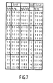
- Fig. 7 shows the table of Fig. 6 in more detailed form in order to translate the encoding rules into an encoding gate circuit.
- the parameter z 1 (n) may have values of + 4 and -4, respectively, +2 and -2, respectively, and zero.
- the first column gives the 2-bit input word.
- the second column gives the value of the running sum z 1 (i) over all the preceding words in 2-bit notation and decimal notation, the third column gives the output code word to be selected, the fourth column the value of the sum z 1 (n) of this code word, and the fifth column gives the new value of the running sum z 1 (i + n) in two-bit notation and decimal notation.
- the input words 00 and 01 are converted into the words 1001 and 0110, respectively, regardless of the running sum z 1 (i), which words each exhibit a sum z 1 (n) equal to zero, so that z 1 (i + n) remains equal to z l (i).
- Fig. 8 shows an example of encoding and decoding in conformity with the table of Fig. 7.
- the input bits a 2 and a 3 and the parameter z 1 (i) representing bits a 0 and a 1 are converted into output bits b 2 , b 3 , b 4 and b 5 and the parameter z i (i + 4) representing the bits b 0 and b 1 in conformity with the indication in the second row of the table in Fig. 7.
- bits a3, a 2 , a 1 and a 0 are applied to inverting and non-inverting inputs of AND-gates A 0 to A 10 in which they are combined in such a way that on the outputs of these AND-gates A 0 to A 10 the bits c 0 to c 10 appear in conformity with the following logic equations:
- bits c 0 to c 10 are subsequently combined to give bits b 0 to b 5 by OR-gates O 0 to 0 5 in accordance with the following logic equations:
- bits b 3 , b 4 and b 5 are combined to form bits d 1 to d 4 in AND-gates A 11 to A 15 in accordance with the following logic equations:
- Curve I represents the spectrum when the biphase code of Fig. 2 is used
- curve II gives the spectrum when the code of Fig. 7 is used. It can be seen that for low frequencies the code in accordance with the invention produces a smaller signal, as was required.
Landscapes
- Engineering & Computer Science (AREA)
- Theoretical Computer Science (AREA)
- Physics & Mathematics (AREA)
- Spectroscopy & Molecular Physics (AREA)
- Computer Networks & Wireless Communication (AREA)
- Signal Processing (AREA)
- Dc Digital Transmission (AREA)
- Signal Processing For Digital Recording And Reproducing (AREA)
- Compression, Expansion, Code Conversion, And Decoders (AREA)
Abstract

Description
- The invention relates to a method of transmitting information, in which prior to transmission m-bit information words are converted into n-bit code words and after transmission said n-bits code words are re-converted into m-bit information words, where m < n and m and n are positive integers, and in which in order to obtain a d.c. free transmission the possible code words have been selected in such a way that the running sum

- The invention also relates to an encoding device for use in the method.
- Moreover, the invention relates to a decoding device for use in the method.
- Such methods and devices are employed in order to optimise the signal spectrum for transmission. For example, in the case of transmission via a magnetic tape, but also in the case of transmission via other media such as cables, space or optical record carriers, it is desirable to have a d.c. free signal and a spectrum with a minimal low- frequency content in order to obtain room for various control signals such as tracking signals in recording. It is known, inter alia from GB-PS 1,540,617, that a d.c. free code is obtained if the running sum over the consecutively generated bits remains, restricted (a value opposite to the value of a logic "1" being assigned to a logic "0"), which means that there will not be a series of input words which gives rise to a series of code words whose running sum increases towards infinity. The simplest method of guaranteeing this is to use for the code words only those words which have a disparity (which is the sum over the bit value of the code word, i.e. the variation of the running sum caused by this code word) equal to zero, i.e. to use only code words comprising as many ones as zeros. An example of this is the "biphase" code in accordance with the table in Fig. 2. Another simple method, whih results in a larger number of possible code words and which is therefore more efficient, is described in said Britisch Patent Specification. In addition to code words of zero disparity, code words of a specific non-zero disparity are permissible, both a code word of positive disparity and a code word of a disparity opposite thereto being assigned to the relevant input words (for example +2 and -2), from which two code words a choice is made which depends on the digital sum value (running sum) over the preceding code words, in such a way that absolute value of this digital sum value remains restricted. The simplest solution is to select one set and to generate the associated words of the other set by inverting the words of said one set.
- The invention aims at providing a method of the kind defined in the opening paragraph, and an encoding device and a aecoding device for use in this method, in which the spectrum of the code words generated in the case of a random supply of information words has a low- frequency signal content which is smaller than in the case of the known method and devices.
- The method in accordance with the invention is therefore characterized in that in addition the possible code words are selected in such a way that the running sum

- The invention is based on the recognition of the fact by limiting the sum

- The method in accordance with the invention may be characterized further in that to a first group of information words code words are assigned which comply with


- The encoding device in accordance with the invention may be characterized in that the parameters a and b are equal.
- The decoding device in accordance with the invention may be characterized by a conversion circuit for converting the m-bit information words into n-bit code words in such a way that the running sum

- The invention will now be described in more detail, by way of example, with reference to the accompanying drawings, in which:
- Fig. 1 shows a known device using a method of transmitting information,
- Fig. 2 shows a conversion table used in a known encoding/decoding method,
- Fig. 3 shows a table for an encoding/decoding method in accordance with the invention,
- Fig. 4 shows a table to illustrate the efficiency R of a group of encoding/decoding methods in accordance with the invention,
- Fig. 5 is a table illustrating the effiency of another group of encoding/decoding methods in accordance with the invention,
- Fig. 6 is a table relating to a preferred version of an encoding/decoding method in accordance with the invention,
- Fig. 7 is a table to explain the use of the code in accordance with the table of Fig. 6,
- Fig. 8 shows a device using the preferred version of the method in accordance with the invention, and
- Fig. 9 is a graph illustrating the effect of the invention and showing the energy spectrum obtained when the codes of the tables of Figs, 2 and 6 are used.
- Fig. 1 shows a device employing a system of encoding and decoding digital data. The device comprises an
input 1 for receiving serial input data and (unless the data is presented in parallel form) applying said data to a series-to-parallel converter 2 for arranging the input data in 2-bit parallel words in the present example. These 2-bit words are applied to anencoding circuit 3, for example in the form of a look-up table or a gate circuit, which encoding circuit, in the present example, generates a 4-bit output word for every input word in conformity with the rules laid down by means of this encoding circuit. By means of a parallel-to-series converter 4 these 4-bit words are converted into a serial data sequence, which is, for example, recorded on a magnetic tape by means of a conventional analog magnetic-tape recorder 6. It is then possible to record, for example, a plurality of parallel tracks. Synchronisation is effected by means of clock signals which are derived from the input signal by a clock-signal generator circuit 5, for example by means of a phase-locked loop. - In principle, decoding may be effected by means of a similar circuit arrangement through which the signals are fed in reverse sequence. The signal from the
tape recorder 6 is arranged in groups of 4- bit words by a series-to-parallel converter 7 (unless the data is available as 4-bit words). These 4-bit words are converted into 2-bit words with adecoder circuit 8 in conformity with rules which are complementary to those used for encoding, and are subsequently converted into a serial data stream onoutput 10 by means of a parallel-to-series converter 9. Again, this process is synchronised with clock signals which are derived, by means of the clock-signal generator circuit 13, from the signal which is obtained from therecorder 6 and which appears oninput 12 of the series-to-parallel converter 7. - Conversion in the
encoding circuit 3 is effected inter alia in order to obtain a signal spectrum which is suitable for transmission. For example, in the case of transmission via a magnetic tape, but also in the case of transmission via other media such as cables, space or optical record carriers, it is desirable to have a d.c. free signal and a spectrum with a minimal low-frequency content to enable various control signals, such as tracking signals in the case of recording, to be accommodated. For example from GB-PS 1,540,617 it is known that a d.c. free code is obtained when the running sum over the consecutively generated bits is limited (a value opposite to the value of a logic "1" being assigned to a logic "0"), which means that there is no series of input words which gives rise to a series of code words whose running sum grows towards infinity. The simplest method of guaranteeing this is to use for the code words only those words whose disparity (which is the sum over the bit value of the code word, i-e. the variation of the running sum caused by this code word) is zero, so only code words comprising as many ones as zeros. An example of this is the "Biphase" code given in the form of a table in Fig. 2. Another simple method which allows more possible code words and is therefore more efficient, is described in said Britisch Patent Specification. Apart from code words with zero disparity, code words with a specific non-zero disparity are also permissible, both a code word of positive disparity and a code word of opposite disparity being assigned to a code word (for example +2 and -2) and a choice being made from these two words depending on the digital sum value (running sum) over the preceding code words, in such a way that the absolute value of this digital sum value remains restricted. The simplest way is to select one set and to generate the associated words of the other set by inverting the words of the first- mentioned set. - In the device shown in Fig. 1 this can be achieved by determining the digital sum value over all the preceding words with an up/down
counter 14 which counts down upon receipt of every logic zero and which counts up upon receipt of every logic one and by generating as a function thereof a logic signal S0/S1 which indicates whether this digital sum value has a high (S1) or a low (So) value of two possible values. If the value of S0 is low, the next input word is converted into a word of zero or +2 disparity in conformity with the obtaining rules, so that the digital sum value remains So or becomes S1 (S1 =S0 + 2) and, if the value of S1 is high, this input word is converted into a word of zero or -2 disparity, so that the digital sum value remains S1 or becomes So (So = S1-2). - During decoding the digital sum value of all the preceding words is determined by means of the up/down
counter 15 in order to determine as a function thereof whether during encoding a word of 0 or +2 disparity or a word of 0 or -2 disparity has been selected as the next code word. Thedecoding circuit 8 is controlled as a function of this. Both the encoding and the decoding circuit therefore comprise a set of code words So, obtained by means of rules or tables, which is valid if the digital sum value of all the preceding code words is So and a set S1 which is valid if the digital sum value of all the preceding words is S1. - In accordance with the afore-mentioned Patent Specification one set S1 can be derived simply from the other set S0 when the words of zero disparity in both sets are selected to be indentical and the words of -2 disparity are selected to be complementary to the words of +2 disparity. The Applicant's Patent Application 8402444 (PHN 11.127) describes an improvement to this method.
- Mathematically, the above may be defined as follows:


ω 0 when the sum z1 (i) over all i preceding sums of k bits is restricted. In practice, the second derivative S" (ω) being zero means that the low-frequency content of the spectrum is even smaller than in the case in which only S(ω =0) is zero, which may improve the usefulness of the code. - A further reduction of the low-frequency content can be obtained if:

- Similarly, this requirement may be imposed on z3(i), z 4(i), z5(i)....zp(i)....., i.e, a summation every time. In general, it may be stated that

- Requirement (3), like requirement (1). can be met by imposing this requirement on every code word; this means that only those code words should be selected which for everv n-bit code word comply with:


- Similarly, the simplest way of meeting requirement (5) is to impose this requirement on every word. In general, this is met if every code word complies with:

- Another method of simply meeting requirement (3) is to select for each input word two code words for which the parameters z1(n) have non-zero values, as the case may be together with code words whose parameters z1(n) are zero, and to select one of the two code words as a function of the logic sum z1(i) over all i/n preceding n-bit words, in such a way that this running sum z1(i) remains restricted. In addition, to meet requirement (1) that the running sum zo(i) (= digital sum value) remains restricted, any appropriate method may be adopted. A suitable choice is the choice for code words of non-zero disparity (zo(n) = 0). If in addition those code words are selected whose sum z1(n) is also zero, the table in Fig. 4 gives the number M of possible code words which can be formed with n-bit words and the attainable efficiency R = 2log (M)/n. It is evident that for a more or less acceptable efficiency (for example, R ≥ 0.5) comparatively long code words of 16 or more bits have to be selected (all the code words should have a length equal to a multiple of 4 bits to meet the requirement that both zo(n) and z1(n) should be zero).
- More efficient codes appear to be possible by maintaining the requirement zo(n) = 0 and admitting more values of z1(n). The table of Fig. 5 shows the code efficiency R, in which the first column gives the number of bits n of the code words and above each column the number of possible values r is given which the parameter z1(i) may assume at the end of each code word.
- The table in Fig. 6 gives an example of a code where n = 4 and r = 4 (Fig. 5), which code is equivalent to the said biphase code (Fig. 2) as regards the efficiency R and the length of the code words. The first column of the table shows the 2-bit input word, the second column gives the associated 4-bit output word when the parameter z1(i) over all the preceding words is smaller than zero, the third column gives the value of z1(n) of this word, the fourth column gives the output word when the parameter z1(i) over all the preceding words is greater than zero, and the fifth column gives the value of z1(n) over this word. At the end of every word z1(i) then always has the four possible values +3, +1, -1 and -3.
- Fig. 7 shows the table of Fig. 6 in more detailed form in order to translate the encoding rules into an encoding gate circuit.
- In this example the parameter z1(n) may have values of +4 and -4, respectively, +2 and -2, respectively, and zero. The first column gives the 2-bit input word. The second column gives the value of the running sum z1(i) over all the preceding words in 2-bit notation and decimal notation, the third column gives the output code word to be selected, the fourth column the value of the sum z1(n) of this code word, and the fifth column gives the new value of the running sum z1(i + n) in two-bit notation and decimal notation.
- As is shown in the table, the
input words words input word 10 is converted into anoutput word 0101 with z1(n) _ = -2 when the sum z1(i) was equal to 00 or 01 (+3 and +1, respectively) and into anoutput word 1010 with z1(n) = +2 when the sum z1(i) was 10 or 11 (-1 and -3, respectively). Similarly, theinput word 11 is converted into anoutput word 0011 with z1(n) = -4 when the sum z1(i) was 00 or 01 and into anoutput word 1100 with z1(n) = +4 when this sum z1(i) was 10 or 11. - The code of Fig. 7 can be decoded without determining the parameter z1(i), because all the code words can be re-converted unambiguously into the original data words. This is even possible with only 3 of the 4 bits. This is because the code words have been selected with the requirement that zo(n) - 0, i.e. code words comprising as many ones as zeros. Therefore, the information is defined by 3 of the 4 bits; the fourth bit merely ensures that z0(n) = 0.
- Fig. 8 shows an example of encoding and decoding in conformity with the table of Fig. 7. The device corresponds to that of Fig. 1 except for the
sections encoding device 3 the input bits a2 and a3 and the parameter z1(i) representing bits a0 and a1 are converted into output bits b2, b3, b4 and b5 and the parameter zi(i + 4) representing the bits b0 and b1 in conformity with the indication in the second row of the table in Fig. 7. - The bits a3, a2, a1 and a0 are applied to inverting and non-inverting inputs of AND-gates A0 to A10 in which they are combined in such a way that on the outputs of these AND-gates A0 to A10 the bits c0 to c10 appear in conformity with the following logic equations:


- These bits c0 to c10 are subsequently combined to give bits b0 to b5 by OR-gates O0 to 05 in accordance with the following logic equations:


- The bits b0 and b1 represent the new value of the parameter z1 =z1 (i + 4) and are applied to the flip-flops FF1 and FF2 where they are latched until the next input word a2, a3 is converted.
- In the
decoding circuit 8 the bits b3, b4 and b5 are combined to form bits d1 to d4 in AND-gates A11 to A15 in accordance with the following logic equations:


- By means of OR-
gates 06 and O7 these bits d0 to d4 are combined to form the output bits a3 and a2 in conformity with the logic equations

- To illustrate the effect of the encoding method in accordance with the invention Fig. 9 shows the energy spectrum S(LJ) in dB as a function of the relative angular frequency ω/ωo (ωo is the channel bit frequency, which spectrum is symmetrical aboutl ω/ωo = 0.5) on a logarithmic scale. Curve I represents the spectrum when the biphase code of Fig. 2 is used an curve II gives the spectrum when the code of Fig. 7 is used. It can be seen that for low frequencies the code in accordance with the invention produces a smaller signal, as was required.
Claims (7)
Applications Claiming Priority (2)
| Application Number | Priority Date | Filing Date | Title |
|---|---|---|---|
| NL8403078A NL8403078A (en) | 1984-10-10 | 1984-10-10 | METHOD FOR TRANSFERRING INFORMATION, CODER FOR APPLICATION IN THE METHOD AND DECODER FOR APPLICATION IN THE METHOD |
| NL8403078 | 1984-10-10 |
Publications (3)
| Publication Number | Publication Date |
|---|---|
| EP0178027A2 true EP0178027A2 (en) | 1986-04-16 |
| EP0178027A3 EP0178027A3 (en) | 1989-03-15 |
| EP0178027B1 EP0178027B1 (en) | 1991-09-25 |
Family
ID=19844589
Family Applications (1)
| Application Number | Title | Priority Date | Filing Date |
|---|---|---|---|
| EP85201620A Expired - Lifetime EP0178027B1 (en) | 1984-10-10 | 1985-10-07 | Method of transmitting information, encoding devide for use in the method, and decoding device for use in the method |
Country Status (7)
| Country | Link |
|---|---|
| US (1) | US4750138A (en) |
| EP (1) | EP0178027B1 (en) |
| JP (1) | JPH0824311B2 (en) |
| KR (1) | KR930002136B1 (en) |
| CA (1) | CA1243123A (en) |
| DE (1) | DE3584217D1 (en) |
| NL (1) | NL8403078A (en) |
Cited By (3)
| Publication number | Priority date | Publication date | Assignee | Title |
|---|---|---|---|---|
| AU620995B2 (en) * | 1989-05-31 | 1992-02-27 | International Computers Limited | Data transmission code |
| EP0556980A1 (en) * | 1992-02-21 | 1993-08-25 | Advanced Micro Devices, Inc. | Method and circuit for performing running disparity measurements |
| WO1994021051A1 (en) * | 1993-03-10 | 1994-09-15 | Awacs Communications (Nz) Limited | Enhanced one way radio seven bit data network |
Families Citing this family (7)
| Publication number | Priority date | Publication date | Assignee | Title |
|---|---|---|---|---|
| GB8708010D0 (en) * | 1987-04-03 | 1987-05-07 | Crosfield Electronics Ltd | Image reprocessing |
| NL9002772A (en) * | 1990-09-21 | 1992-04-16 | Philips Nv | DEVICE FOR RECORDING A DIGITAL INFORMATION SIGNAL IN A RECORD CARRIER. |
| US5625644A (en) * | 1991-12-20 | 1997-04-29 | Myers; David J. | DC balanced 4B/8B binary block code for digital data communications |
| US5450443A (en) * | 1993-09-01 | 1995-09-12 | International Business Machines Corporation | Method and apparatus for constructing asymptotically optimal second order DC-free channel codes |
| JP3184083B2 (en) * | 1995-12-15 | 2001-07-09 | 日本電気株式会社 | Channel demultiplexing method and channel demultiplexing apparatus |
| JP3916055B2 (en) * | 2002-03-28 | 2007-05-16 | 日本ビクター株式会社 | Modulation method, modulation device, recording medium, demodulation method and demodulation device |
| JP2014093682A (en) | 2012-11-05 | 2014-05-19 | Denso Corp | Communication system |
Citations (5)
| Publication number | Priority date | Publication date | Assignee | Title |
|---|---|---|---|---|
| DE1963945A1 (en) * | 1969-12-20 | 1971-06-24 | Ibm | Encoder |
| US4261019A (en) * | 1979-11-29 | 1981-04-07 | Micropolis Corporation | Compatible digital magnetic recording system |
| FR2469047A1 (en) * | 1979-11-02 | 1981-05-08 | Sony Corp | METHOD AND APPARATUS FOR ENCODING A DIGITAL SIGNAL SO THAT IT PRESENTS A LOW DIRECT CURRENT COMPONENT, AS WELL AS FOR DECODING IT |
| FR2469046A1 (en) * | 1979-10-29 | 1981-05-08 | Sony Corp | IMPROVED METHOD AND APPARATUS FOR ENCODING A DIGITAL SIGNAL SO THAT IT PRESENTS A MINIMUM DIRECT CURRENT COMPONENT |
| GB2094107A (en) * | 1981-01-16 | 1982-09-08 | Standard Telephones Cables Ltd | Digital code for line transmission |
Family Cites Families (5)
| Publication number | Priority date | Publication date | Assignee | Title |
|---|---|---|---|---|
| GB1540617A (en) * | 1968-12-13 | 1979-02-14 | Post Office | Transformation of binary coded signals into a form having lower disparity |
| JPS59169254A (en) * | 1983-03-16 | 1984-09-25 | Hitachi Ltd | Code converting system |
| JPH0714145B2 (en) * | 1983-04-26 | 1995-02-15 | ソニー株式会社 | Information conversion method |
| NL8402445A (en) * | 1984-01-20 | 1985-08-16 | Philips Nv | METHOD FOR CODING N-BITS INFORMATION WORDS TO M-BITS CODEWORDS, DEVICE FOR PERFORMING THAT METHOD, METHOD FOR DECODING M-BITS CODE-WORDS, AND DEVICE FOR PERFORMING THAT METHOD |
| NL8402444A (en) * | 1984-01-20 | 1986-03-03 | Philips Nv | METHOD FOR TRANSFERRING INFORMATION, CODER FOR APPLICATION IN THE METHOD AND DECODER FOR APPLICATION IN THE METHOD |
-
1984
- 1984-10-10 NL NL8403078A patent/NL8403078A/en not_active Application Discontinuation
-
1985
- 1985-03-11 US US06/710,659 patent/US4750138A/en not_active Expired - Fee Related
- 1985-10-03 CA CA000492139A patent/CA1243123A/en not_active Expired
- 1985-10-07 DE DE8585201620T patent/DE3584217D1/en not_active Expired - Lifetime
- 1985-10-07 EP EP85201620A patent/EP0178027B1/en not_active Expired - Lifetime
- 1985-10-10 KR KR1019850007445A patent/KR930002136B1/en not_active IP Right Cessation
- 1985-10-11 JP JP60224979A patent/JPH0824311B2/en not_active Expired - Lifetime
Patent Citations (5)
| Publication number | Priority date | Publication date | Assignee | Title |
|---|---|---|---|---|
| DE1963945A1 (en) * | 1969-12-20 | 1971-06-24 | Ibm | Encoder |
| FR2469046A1 (en) * | 1979-10-29 | 1981-05-08 | Sony Corp | IMPROVED METHOD AND APPARATUS FOR ENCODING A DIGITAL SIGNAL SO THAT IT PRESENTS A MINIMUM DIRECT CURRENT COMPONENT |
| FR2469047A1 (en) * | 1979-11-02 | 1981-05-08 | Sony Corp | METHOD AND APPARATUS FOR ENCODING A DIGITAL SIGNAL SO THAT IT PRESENTS A LOW DIRECT CURRENT COMPONENT, AS WELL AS FOR DECODING IT |
| US4261019A (en) * | 1979-11-29 | 1981-04-07 | Micropolis Corporation | Compatible digital magnetic recording system |
| GB2094107A (en) * | 1981-01-16 | 1982-09-08 | Standard Telephones Cables Ltd | Digital code for line transmission |
Non-Patent Citations (3)
| Title |
|---|
| IBM TECHNICAL DISCLOSURE BULLETIN, vol. 24, no. 6, November 1981, pages 2759-2762, New York, US; J.A. ROONEY: "DC limited recording code and implementation" * |
| IBM TECHNICAL DISCLOSURE BULLETIN, vol. 24, no. 8, January 1982, pages 4087-4089, New York, US; P.A. FRANASZEK et al.: "DC balanced run-length limited code" * |
| S.M.P.T.E. JOURNAL, vol. 92, no. 9, September 1983, pages 918-922, Scarsdale, New York, US; H. YOSHIDA et al.: "8-9 block code: A DE-free channel code for digital magnetic recording" * |
Cited By (3)
| Publication number | Priority date | Publication date | Assignee | Title |
|---|---|---|---|---|
| AU620995B2 (en) * | 1989-05-31 | 1992-02-27 | International Computers Limited | Data transmission code |
| EP0556980A1 (en) * | 1992-02-21 | 1993-08-25 | Advanced Micro Devices, Inc. | Method and circuit for performing running disparity measurements |
| WO1994021051A1 (en) * | 1993-03-10 | 1994-09-15 | Awacs Communications (Nz) Limited | Enhanced one way radio seven bit data network |
Also Published As
| Publication number | Publication date |
|---|---|
| CA1243123A (en) | 1988-10-11 |
| KR860003715A (en) | 1986-05-28 |
| DE3584217D1 (en) | 1991-10-31 |
| US4750138A (en) | 1988-06-07 |
| NL8403078A (en) | 1986-05-01 |
| JPS61154246A (en) | 1986-07-12 |
| EP0178027B1 (en) | 1991-09-25 |
| KR930002136B1 (en) | 1993-03-26 |
| EP0178027A3 (en) | 1989-03-15 |
| JPH0824311B2 (en) | 1996-03-06 |
Similar Documents
| Publication | Publication Date | Title |
|---|---|---|
| US4786890A (en) | Method and apparatus for implementing a PRML code | |
| JPH0519332B2 (en) | ||
| EP0178027A2 (en) | Method of transmitting information, encoding devide for use in the method, and decoding device for use in the method | |
| US4802190A (en) | Method of transmitting information by means of code signals, information transmission system for carrying out the method, and transmitting and receiving apparatus for use in the transmission system | |
| EP0557130B1 (en) | Data conversion method and recording/reproducing apparatus using the same | |
| US6347390B1 (en) | Data encoding method and device, data decoding method and device, and data supply medium | |
| EP0090047B1 (en) | Encoding and decoding system for binary data | |
| KR100462536B1 (en) | Transmission, Recording, and Playback of Digital Information Signals | |
| US4881076A (en) | Encoding for pit-per-transition optical data recording | |
| US4536742A (en) | Method of encoding a stream of data bits, device for carring out the method, and device for decoding a stream of data bits | |
| US4186375A (en) | Magnetic storage systems for coded numerical data with reversible transcoding into high density bipolar code of order n | |
| KR20040033022A (en) | Modulation code system and methods of encoding and decoding a signal by multiple integration | |
| US5602547A (en) | Data conversion apparatus and encoding apparatus | |
| US5130862A (en) | Coding apparatus for converting digital signals into ternary signals whose dc component is equal to zero | |
| JPS60106254A (en) | 4-6 group modulation method | |
| JP3882308B2 (en) | Code division method | |
| JP2962027B2 (en) | Information conversion method and information recording device | |
| JP2713011B2 (en) | Information conversion method and information recording device / information reproducing device | |
| EP0064791A1 (en) | Method of transmitting an audio signal via a transmission channel | |
| JP2573067B2 (en) | Information conversion device | |
| JPH05235775A (en) | Information conversion method and information converter adopting said method | |
| JPS6184124A (en) | Digital modulator | |
| Nicholas | Source codes for the output of a delta modulator operating on speech | |
| JPH02224527A (en) | Information conversion system | |
| JPS635826B2 (en) |
Legal Events
| Date | Code | Title | Description |
|---|---|---|---|
| PUAI | Public reference made under article 153(3) epc to a published international application that has entered the european phase |
Free format text: ORIGINAL CODE: 0009012 |
|
| AK | Designated contracting states |
Kind code of ref document: A2 Designated state(s): DE FR GB SE |
|
| PUAL | Search report despatched |
Free format text: ORIGINAL CODE: 0009013 |
|
| AK | Designated contracting states |
Kind code of ref document: A3 Designated state(s): DE FR GB SE |
|
| 17P | Request for examination filed |
Effective date: 19890831 |
|
| 17Q | First examination report despatched |
Effective date: 19901025 |
|
| GRAA | (expected) grant |
Free format text: ORIGINAL CODE: 0009210 |
|
| AK | Designated contracting states |
Kind code of ref document: B1 Designated state(s): DE FR GB SE |
|
| REF | Corresponds to: |
Ref document number: 3584217 Country of ref document: DE Date of ref document: 19911031 |
|
| ET | Fr: translation filed | ||
| PLBE | No opposition filed within time limit |
Free format text: ORIGINAL CODE: 0009261 |
|
| STAA | Information on the status of an ep patent application or granted ep patent |
Free format text: STATUS: NO OPPOSITION FILED WITHIN TIME LIMIT |
|
| 26N | No opposition filed | ||
| EAL | Se: european patent in force in sweden |
Ref document number: 85201620.3 |
|
| REG | Reference to a national code |
Ref country code: FR Ref legal event code: CD |
|
| PGFP | Annual fee paid to national office [announced via postgrant information from national office to epo] |
Ref country code: GB Payment date: 19960930 Year of fee payment: 12 |
|
| PGFP | Annual fee paid to national office [announced via postgrant information from national office to epo] |
Ref country code: FR Payment date: 19961022 Year of fee payment: 12 |
|
| PGFP | Annual fee paid to national office [announced via postgrant information from national office to epo] |
Ref country code: SE Payment date: 19961025 Year of fee payment: 12 |
|
| PGFP | Annual fee paid to national office [announced via postgrant information from national office to epo] |
Ref country code: DE Payment date: 19961218 Year of fee payment: 12 |
|
| PG25 | Lapsed in a contracting state [announced via postgrant information from national office to epo] |
Ref country code: GB Free format text: LAPSE BECAUSE OF NON-PAYMENT OF DUE FEES Effective date: 19971007 |
|
| PG25 | Lapsed in a contracting state [announced via postgrant information from national office to epo] |
Ref country code: SE Free format text: LAPSE BECAUSE OF NON-PAYMENT OF DUE FEES Effective date: 19971008 |
|
| PG25 | Lapsed in a contracting state [announced via postgrant information from national office to epo] |
Ref country code: FR Free format text: THE PATENT HAS BEEN ANNULLED BY A DECISION OF A NATIONAL AUTHORITY Effective date: 19971031 |
|
| GBPC | Gb: european patent ceased through non-payment of renewal fee |
Effective date: 19971007 |
|
| PG25 | Lapsed in a contracting state [announced via postgrant information from national office to epo] |
Ref country code: DE Free format text: LAPSE BECAUSE OF NON-PAYMENT OF DUE FEES Effective date: 19980701 |
|
| EUG | Se: european patent has lapsed |
Ref document number: 85201620.3 |
|
| REG | Reference to a national code |
Ref country code: FR Ref legal event code: ST |