EP0178024B1 - Direct luminescent cathode ray device with improved color filtering system - Google Patents
Direct luminescent cathode ray device with improved color filtering system Download PDFInfo
- Publication number
- EP0178024B1 EP0178024B1 EP85201617A EP85201617A EP0178024B1 EP 0178024 B1 EP0178024 B1 EP 0178024B1 EP 85201617 A EP85201617 A EP 85201617A EP 85201617 A EP85201617 A EP 85201617A EP 0178024 B1 EP0178024 B1 EP 0178024B1
- Authority
- EP
- European Patent Office
- Prior art keywords
- cathode ray
- ray tube
- tube device
- faceplate
- filtering means
- Prior art date
- Legal status (The legal status is an assumption and is not a legal conclusion. Google has not performed a legal analysis and makes no representation as to the accuracy of the status listed.)
- Expired
Links
- 238000001914 filtration Methods 0.000 title claims description 18
- 230000005855 radiation Effects 0.000 claims description 33
- LYCAIKOWRPUZTN-UHFFFAOYSA-N Ethylene glycol Chemical compound OCCO LYCAIKOWRPUZTN-UHFFFAOYSA-N 0.000 claims description 18
- 150000001206 Neodymium Chemical class 0.000 claims description 10
- 239000002904 solvent Substances 0.000 claims description 10
- LFQSCWFLJHTTHZ-UHFFFAOYSA-N Ethanol Chemical compound CCO LFQSCWFLJHTTHZ-UHFFFAOYSA-N 0.000 claims description 7
- 150000000922 Holmium Chemical class 0.000 claims description 7
- OKKJLVBELUTLKV-UHFFFAOYSA-N Methanol Chemical compound OC OKKJLVBELUTLKV-UHFFFAOYSA-N 0.000 claims description 6
- 229910002651 NO3 Inorganic materials 0.000 claims description 5
- NHNBFGGVMKEFGY-UHFFFAOYSA-N Nitrate Chemical compound [O-][N+]([O-])=O NHNBFGGVMKEFGY-UHFFFAOYSA-N 0.000 claims description 5
- XLYOFNOQVPJJNP-UHFFFAOYSA-N water Substances O XLYOFNOQVPJJNP-UHFFFAOYSA-N 0.000 claims description 5
- 229910052693 Europium Inorganic materials 0.000 claims description 4
- KFZMGEQAYNKOFK-UHFFFAOYSA-N Isopropanol Chemical compound CC(C)O KFZMGEQAYNKOFK-UHFFFAOYSA-N 0.000 claims description 4
- OAICVXFJPJFONN-UHFFFAOYSA-N Phosphorus Chemical compound [P] OAICVXFJPJFONN-UHFFFAOYSA-N 0.000 claims description 3
- 238000010894 electron beam technology Methods 0.000 claims description 3
- -1 europium-activated phosphor Chemical class 0.000 claims description 3
- DNIAPMSPPWPWGF-VKHMYHEASA-N (+)-propylene glycol Chemical compound C[C@H](O)CO DNIAPMSPPWPWGF-VKHMYHEASA-N 0.000 claims description 2
- DNIAPMSPPWPWGF-GSVOUGTGSA-N (R)-(-)-Propylene glycol Chemical compound C[C@@H](O)CO DNIAPMSPPWPWGF-GSVOUGTGSA-N 0.000 claims description 2
- YPFDHNVEDLHUCE-UHFFFAOYSA-N 1,3-propanediol Substances OCCCO YPFDHNVEDLHUCE-UHFFFAOYSA-N 0.000 claims description 2
- 229910052779 Neodymium Inorganic materials 0.000 claims description 2
- DNIAPMSPPWPWGF-UHFFFAOYSA-N monopropylene glycol Natural products CC(O)CO DNIAPMSPPWPWGF-UHFFFAOYSA-N 0.000 claims description 2
- QEFYFXOXNSNQGX-UHFFFAOYSA-N neodymium atom Chemical compound [Nd] QEFYFXOXNSNQGX-UHFFFAOYSA-N 0.000 claims description 2
- 229920000166 polytrimethylene carbonate Polymers 0.000 claims description 2
- BDERNNFJNOPAEC-UHFFFAOYSA-N propan-1-ol Chemical compound CCCO BDERNNFJNOPAEC-UHFFFAOYSA-N 0.000 claims description 2
- 235000013772 propylene glycol Nutrition 0.000 claims description 2
- 150000003839 salts Chemical class 0.000 claims description 2
- 239000000203 mixture Substances 0.000 claims 4
- WVDDGKGOMKODPV-ZQBYOMGUSA-N phenyl(114C)methanol Chemical compound O[14CH2]C1=CC=CC=C1 WVDDGKGOMKODPV-ZQBYOMGUSA-N 0.000 claims 1
- 239000000243 solution Substances 0.000 description 12
- 239000011521 glass Substances 0.000 description 4
- PEDCQBHIVMGVHV-UHFFFAOYSA-N Glycerine Chemical compound OCC(O)CO PEDCQBHIVMGVHV-UHFFFAOYSA-N 0.000 description 3
- 229910052689 Holmium Inorganic materials 0.000 description 3
- 239000002826 coolant Substances 0.000 description 3
- KJZYNXUDTRRSPN-UHFFFAOYSA-N holmium atom Chemical compound [Ho] KJZYNXUDTRRSPN-UHFFFAOYSA-N 0.000 description 3
- XMBWDFGMSWQBCA-UHFFFAOYSA-N hydrogen iodide Chemical compound I XMBWDFGMSWQBCA-UHFFFAOYSA-N 0.000 description 2
- MRELNEQAGSRDBK-UHFFFAOYSA-N lanthanum(3+);oxygen(2-) Chemical compound [O-2].[O-2].[O-2].[La+3].[La+3] MRELNEQAGSRDBK-UHFFFAOYSA-N 0.000 description 2
- 230000003595 spectral effect Effects 0.000 description 2
- CPELXLSAUQHCOX-UHFFFAOYSA-M Bromide Chemical compound [Br-] CPELXLSAUQHCOX-UHFFFAOYSA-M 0.000 description 1
- VEXZGXHMUGYJMC-UHFFFAOYSA-M Chloride anion Chemical compound [Cl-] VEXZGXHMUGYJMC-UHFFFAOYSA-M 0.000 description 1
- 229910017504 Nd(NO3)3 Inorganic materials 0.000 description 1
- 229910052770 Uranium Inorganic materials 0.000 description 1
- 150000001298 alcohols Chemical class 0.000 description 1
- 230000004075 alteration Effects 0.000 description 1
- POJOORKDYOPQLS-UHFFFAOYSA-L barium(2+) 5-chloro-2-[(2-hydroxynaphthalen-1-yl)diazenyl]-4-methylbenzenesulfonate Chemical compound [Ba+2].C1=C(Cl)C(C)=CC(N=NC=2C3=CC=CC=C3C=CC=2O)=C1S([O-])(=O)=O.C1=C(Cl)C(C)=CC(N=NC=2C3=CC=CC=C3C=CC=2O)=C1S([O-])(=O)=O POJOORKDYOPQLS-UHFFFAOYSA-L 0.000 description 1
- 238000001816 cooling Methods 0.000 description 1
- 239000013078 crystal Substances 0.000 description 1
- 238000010790 dilution Methods 0.000 description 1
- 239000012895 dilution Substances 0.000 description 1
- RUZYUOTYCVRMRZ-UHFFFAOYSA-N doxazosin Chemical compound C1OC2=CC=CC=C2OC1C(=O)N(CC1)CCN1C1=NC(N)=C(C=C(C(OC)=C2)OC)C2=N1 RUZYUOTYCVRMRZ-UHFFFAOYSA-N 0.000 description 1
- 230000000694 effects Effects 0.000 description 1
- OGPBJKLSAFTDLK-UHFFFAOYSA-N europium atom Chemical compound [Eu] OGPBJKLSAFTDLK-UHFFFAOYSA-N 0.000 description 1
- 230000005284 excitation Effects 0.000 description 1
- 238000007710 freezing Methods 0.000 description 1
- 230000008014 freezing Effects 0.000 description 1
- 150000002603 lanthanum Chemical class 0.000 description 1
- 239000007788 liquid Substances 0.000 description 1
- 239000000463 material Substances 0.000 description 1
- 238000000034 method Methods 0.000 description 1
- 230000003287 optical effect Effects 0.000 description 1
- 238000009877 rendering Methods 0.000 description 1
- 229920006395 saturated elastomer Polymers 0.000 description 1
- PYOOBRULIYNHJR-UHFFFAOYSA-K trichloroholmium Chemical compound Cl[Ho](Cl)Cl PYOOBRULIYNHJR-UHFFFAOYSA-K 0.000 description 1
Images
Classifications
-
- H—ELECTRICITY
- H01—ELECTRIC ELEMENTS
- H01J—ELECTRIC DISCHARGE TUBES OR DISCHARGE LAMPS
- H01J29/00—Details of cathode-ray tubes or of electron-beam tubes of the types covered by group H01J31/00
- H01J29/86—Vessels; Containers; Vacuum locks
- H01J29/89—Optical or photographic arrangements structurally combined or co-operating with the vessel
- H01J29/898—Spectral filters
Definitions
- the invention relates to a cathode ray tube device for generating a bright red light spot comprising:
- Such a cathode ray tube device is known from GB-A-2,093,269.
- Red light radiation for use in, for instance, a projection color television generally is produced by the electronic bombardment of red luminescent europium-activated phosphors.
- the phosphors when excited by electronic bombardment produce a high amount of the desired radiation with a peak at 620 nm.
- a significant amount of radiation is produced in the 580 to 600 nm region and the 620 to 660 nm region in addition to the desired main peak at 610 nm.
- GB-A-2,093,269 shows the use of a faceplate containing Nd 2 0 3 .
- Japanese Patent 57-180859 shows the use of a glass filter plate containing Nd 2 0 3 and a small amount of Cr 2 0 3 or Pr 2 0 3 .
- Seward et al, U.S. Patent 4,086,089 employs glass faceplates for color television tubes, which faceplates function as filters.
- the face plates of Seward contain Na 2 0, F, AgHal and Si0 2 .
- the NL Patent 144.063 shows a salt optical filter employing a lanthanum salt or a lanthanum oxide.
- the filtering means disclosed in these patents have not been found to be capable of substantially reducing undesired radiation surrounding the desired 610 nm radiation peak without significantly reducing the desired 610 nm radiation peak.
- a principle object of this invention is to provide a cathode ray tube (CRT) device for generating a brilliant red light spot in which there is a significant reduction in the radiation from undesired areas surrounding the desired radiation at 610 nm and there is no significant reduction of the desired radiation peak at 610 nm.
- Another object of this invention is to provide an externally-liquid cooled CRT device for generating a bright red light spot for projection television and information displays in which troublesome radiations in the 580 to 600 nm region and the 620 to 660 nm region are significantly reduced without significant reduction at the desired radiation peak at 610 nm.
- a cathode ray tube device is thereto characterized in that the light filtering means is situated outside of the outer surface of said faceplate and comprises a container containing a concentrated solution of a soluble holmium salt and a soluble neodymium salt.
- a light filtering means comprising a solution filled in a container and situated outside of the outer surface of the faceplate is known per se from GB-A-2,098,393.
- any soluble holmium salt and soluble neodymium salt may be employed.
- neodymium salts that may be employed are bromide, chloride, iodide and nitrate.
- the holmium salts that may be employed are the holmium chloride, iodide and the nitrate.
- the solutions contain above 40 to 75 grams of the holmium salt and 75 grams of the neodymium salt per 100 ml of solvent.
- the total concentration of the holmium and the neodymium salt preferably should not exceed 120 grams per 100 ml of solvent.
- a solvent a combination of water and an alcohol may be employed.
- alcohols that may be employed are ethylene glycol, 1,2-propanediol, 1,3-propanediol, glycerol, ethanol, propanol, isopropanol, and methanol.
- the solvent preferably to up to 80% by weight of the solvent consists of the alcohol for in such a case the solution not only acts as a filtering medium but is an excellent coolant for the tube during operation, while rendering the tube resistant to freezing during storage.
- the solvent is 50% by weight of ethylene glycol and 50% by weight of water.
- the solution is preferably carried on the external surface of the faceplate and is held in place by a glass plate or other transparent member sealed to the external surface of the faceplate.
- the solution need not be carried directly on the faceplate of the CRT tube but may be contained in a container located outside of the external surface of the faceplate along as the container is in the path of the radiation emitting from the tube and is transparent to the radiation of the tube.
- the index of refraction of the container matches that of the faceplate.
- red emitting phosphors examples include Y 2 0 3 :Eu, YV0 4 :Eu, YVO 3 :Eu, and Y 2 0 2 S:Eu.
- the phosphor material may be present in the cathode ray tube as a luminescent screen coated on the inner surface of the faceplate but may also be in the form of a single self-supporting crystal only the surface of which is activated.
- a solution of 12 grams of Ho(NO 3 ) ⁇ 5H 2 0 and 12 grams of Nd(NO 3 ) 3 ⁇ 5H 2 0 in 20 ml of 50% H 2 0: 50% ethylene glycol was prepared.
- a .5 cm thick layer of the resultant light-filtering solution 1 was prepared and applied to the external surface 3 of the glass plate 5 of a cathode ray tube 7 supplied with an envelope 9 and containing an electron gun 11 positioned to emit a beam of electrons impinging on the surface of a red luminescent screen 13 formed of a Y 2 0 3 :Eu phosphor deposited on the internal surface 15 of the faceplate.
- the solution layer 1 is held in place on the external surface 3 of the faceplate 5 by transparent cover plate 17 and seals 19.
- the light output of the CRT device upon excitation of the luminescent screen by an impinging electron beam was scanned with a monochrometer in a wavelength range of 500-750 nm to record the result as is shown in the graph of Fig. 2 of the drawing in which the wavelength in nanometers (nm) is plotted on the abscissa and the measured intensity in arbitrary units on the ordinate.
- the light output produced by the identical CRT device except for the omission of the holmium and the neodymium salt in the coolant solution was scanned in the same wavelength range. This result is shown in the curve of the graph of Fig. 3 of the drawing.
Landscapes
- Physics & Mathematics (AREA)
- Spectroscopy & Molecular Physics (AREA)
- Cathode-Ray Tubes And Fluorescent Screens For Display (AREA)
- Common Detailed Techniques For Electron Tubes Or Discharge Tubes (AREA)
- Manufacture Of Electron Tubes, Discharge Lamp Vessels, Lead-In Wires, And The Like (AREA)
- Vessels, Lead-In Wires, Accessory Apparatuses For Cathode-Ray Tubes (AREA)
Description
- The invention relates to a cathode ray tube device for generating a bright red light spot comprising:
- a cathode ray tube including an evacuated envelope, a europium-activated phosphor, capable of emitting red radiation when excited by electrons, positioned within said envelope and in a path of said electron beam and a transparent face plate forming part of said envelope and positioned in the path of said red radiation, the faceplate being provided with a light beam filtering means, which at least in the path of said red radiation is transparent to said radiation, said filtering means containing neodymium.
- Such a cathode ray tube device is known from GB-A-2,093,269.
- Red light radiation for use in, for instance, a projection color television generally is produced by the electronic bombardment of red luminescent europium-activated phosphors. The phosphors when excited by electronic bombardment produce a high amount of the desired radiation with a peak at 620 nm. However, a significant amount of radiation is produced in the 580 to 600 nm region and the 620 to 660 nm region in addition to the desired main peak at 610 nm.
- As a result of this undesired radiation there is some dilution of the desired radiation. Because of the presence of the undesired radiation blurring of the image may occur when the 610 nm radiation image is brought into focus due to the chromatic aberration of the lens system.
- Several methods have been proposed for filtering of undesired radiation from color television tubes.
- GB-A-2,093,269 shows the use of a faceplate containing Nd203.
- Japanese Patent 57-180859 shows the use of a glass filter plate containing Nd203 and a small amount of Cr203 or Pr203. Seward et al, U.S. Patent 4,086,089 employs glass faceplates for color television tubes, which faceplates function as filters. The face plates of Seward contain Na20, F, AgHal and Si02. The NL Patent 144.063 shows a salt optical filter employing a lanthanum salt or a lanthanum oxide.
- However, the filtering means disclosed in these patents have not been found to be capable of substantially reducing undesired radiation surrounding the desired 610 nm radiation peak without significantly reducing the desired 610 nm radiation peak.
- A principle object of this invention is to provide a cathode ray tube (CRT) device for generating a brilliant red light spot in which there is a significant reduction in the radiation from undesired areas surrounding the desired radiation at 610 nm and there is no significant reduction of the desired radiation peak at 610 nm. Another object of this invention is to provide an externally-liquid cooled CRT device for generating a bright red light spot for projection television and information displays in which troublesome radiations in the 580 to 600 nm region and the 620 to 660 nm region are significantly reduced without significant reduction at the desired radiation peak at 610 nm.
- These and other objects of the invention will be apparent from the description that follows.
- A cathode ray tube device according to the invention is thereto characterized in that the light filtering means is situated outside of the outer surface of said faceplate and comprises a container containing a concentrated solution of a soluble holmium salt and a soluble neodymium salt.
- Quite unexpectedly it is found that light emitted from the CRT device exhibits drastically reduced radiation in the 580 to 600 nm region and the 620 to 660 nm region with practically no decrease in the desired radiation peak at 610 nm. As a result, the projected red image is more deeply saturated and of improved sharpness.
- It is remarked here that a light filtering means comprising a solution filled in a container and situated outside of the outer surface of the faceplate is known per se from GB-A-2,098,393.
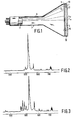
- Fig. 1 is a cross-sectional view of a CRT device of the invention.
- Fig. 2 is of the spectral energy distribution of the radiation emitted from a CRT device of the invention in the range of 500-750 nm and
- Fig. 3 is a graph showing the spectral energy distribution of the radiation emitted from an identical CRT device without the light-filtering means of the invention, also in the range of 500-750 nm.
- Any soluble holmium salt and soluble neodymium salt may be employed. Examples of neodymium salts that may be employed are bromide, chloride, iodide and nitrate. Examples of the holmium salts that may be employed are the holmium chloride, iodide and the nitrate. Preferably the solutions contain above 40 to 75 grams of the holmium salt and 75 grams of the neodymium salt per 100 ml of solvent. The total concentration of the holmium and the neodymium salt preferably should not exceed 120 grams per 100 ml of solvent.
- As a solvent a combination of water and an alcohol may be employed. Examples of alcohols that may be employed are ethylene glycol, 1,2-propanediol, 1,3-propanediol, glycerol, ethanol, propanol, isopropanol, and methanol.
- Preferably to up to 80% by weight of the solvent consists of the alcohol for in such a case the solution not only acts as a filtering medium but is an excellent coolant for the tube during operation, while rendering the tube resistant to freezing during storage.
- Most preferably, the solvent is 50% by weight of ethylene glycol and 50% by weight of water.
- If the solution is to function not only to supress undesired radiation but also as a coolant for the tube, the solution is preferably carried on the external surface of the faceplate and is held in place by a glass plate or other transparent member sealed to the external surface of the faceplate. However, if no cooling effect is desired, the solution need not be carried directly on the faceplate of the CRT tube but may be contained in a container located outside of the external surface of the faceplate along as the container is in the path of the radiation emitting from the tube and is transparent to the radiation of the tube.
- Preferably, the index of refraction of the container matches that of the faceplate.
- Examples of the red emitting phosphors that may be employed in the CRT device of the invention are Y203:Eu, YV04:Eu, YVO3:Eu, and Y202S:Eu. The phosphor material may be present in the cathode ray tube as a luminescent screen coated on the inner surface of the faceplate but may also be in the form of a single self-supporting crystal only the surface of which is activated.
- For a more complete understanding of the invention, the invention will now be described in greater detail with reference to Figure 1 of the drawing which is a cross-sectional view of a preferred embodiment of the CRT device of the invention.
- A solution of 12 grams of Ho(NO3) · 5H20 and 12 grams of Nd(NO3)3 · 5H20 in 20 ml of 50% H20: 50% ethylene glycol was prepared. A .5 cm thick layer of the resultant light-filtering solution 1 was prepared and applied to the external surface 3 of the
glass plate 5 of a cathode ray tube 7 supplied with anenvelope 9 and containing anelectron gun 11 positioned to emit a beam of electrons impinging on the surface of a redluminescent screen 13 formed of a Y203:Eu phosphor deposited on theinternal surface 15 of the faceplate. - The solution layer 1 is held in place on the external surface 3 of the
faceplate 5 bytransparent cover plate 17 andseals 19. - . The light output of the CRT device upon excitation of the luminescent screen by an impinging electron beam was scanned with a monochrometer in a wavelength range of 500-750 nm to record the result as is shown in the graph of Fig. 2 of the drawing in which the wavelength in nanometers (nm) is plotted on the abscissa and the measured intensity in arbitrary units on the ordinate. In a similar fashion, the light output produced by the identical CRT device except for the omission of the holmium and the neodymium salt in the coolant solution was scanned in the same wavelength range. This result is shown in the curve of the graph of Fig. 3 of the drawing.
- Comparison of the results in the graph of Fig. 2 and Fig. 3 of the drawing shows the filtering solution containing the combination of the holmium and neodymium salts produces a significant decrease in the undesired radiation while leaving the desired 610 nm radiation peak virtually unchanged.
Claims (12)
Applications Claiming Priority (2)
| Application Number | Priority Date | Filing Date | Title |
|---|---|---|---|
| US06/659,103 US4626740A (en) | 1984-10-09 | 1984-10-09 | Red luminescent cathode ray device with improved color filtering system |
| US659103 | 1996-06-03 |
Publications (3)
| Publication Number | Publication Date |
|---|---|
| EP0178024A2 EP0178024A2 (en) | 1986-04-16 |
| EP0178024A3 EP0178024A3 (en) | 1986-07-23 |
| EP0178024B1 true EP0178024B1 (en) | 1989-08-30 |
Family
ID=24644039
Family Applications (1)
| Application Number | Title | Priority Date | Filing Date |
|---|---|---|---|
| EP85201617A Expired EP0178024B1 (en) | 1984-10-09 | 1985-10-07 | Direct luminescent cathode ray device with improved color filtering system |
Country Status (5)
| Country | Link |
|---|---|
| US (1) | US4626740A (en) |
| EP (1) | EP0178024B1 (en) |
| JP (1) | JPS6191839A (en) |
| CA (1) | CA1234410A (en) |
| DE (1) | DE3572749D1 (en) |
Families Citing this family (6)
| Publication number | Priority date | Publication date | Assignee | Title |
|---|---|---|---|---|
| US5209690A (en) * | 1988-09-08 | 1993-05-11 | U.S. Philips Corporation | Method of vapor depositing an interference filter layer on the inside of a display window, a display window, a projection cathode ray tube and a projection television apparatus |
| JPH03127436A (en) * | 1989-10-11 | 1991-05-30 | Mitsubishi Electric Corp | Projection-type television apparatus |
| EP0432744B1 (en) * | 1989-12-12 | 1995-05-24 | Kabushiki Kaisha Toshiba | Color cathode ray tube |
| JPH08146216A (en) * | 1994-11-17 | 1996-06-07 | Kureha Chem Ind Co Ltd | Method for manufacturing composite optical filter |
| KR200228838Y1 (en) * | 1995-06-23 | 2001-09-17 | 김순택 | Cathode ray tube with improved safety |
| FR2744584B1 (en) * | 1996-02-02 | 1998-03-06 | Moroque Slucki Guy De | PROTECTION DEVICE FOR MONITOR AND TELEVISION RECEIVER TYPE SCREENS |
Family Cites Families (12)
| Publication number | Priority date | Publication date | Assignee | Title |
|---|---|---|---|---|
| NL246961A (en) * | 1959-01-02 | |||
| US3527711A (en) * | 1963-04-16 | 1970-09-08 | Owens Illinois Inc | Process for preparing rare earth doped luminescent silica glass |
| US3631284A (en) * | 1968-01-19 | 1971-12-28 | Itt | Red-emitting material for cathodoluminescent screens |
| US3638060A (en) * | 1970-05-25 | 1972-01-25 | Gte Laboratories Inc | Phosphor display screen and filter including platinum and manganese chloride derivatives of tetraphenylporphin |
| FR2331040A1 (en) * | 1974-10-16 | 1977-06-03 | Better Environmental Develop C | OPTICAL FILTERS CONTAINING RARE EARTHS |
| US3914010A (en) * | 1974-11-25 | 1975-10-21 | Us Army | Liquid long-wave pass filter for high intensity light source |
| JPS5840815B2 (en) * | 1975-09-30 | 1983-09-08 | 三菱電機株式会社 | cathode ray tube |
| US4070101A (en) * | 1976-09-02 | 1978-01-24 | The United States Of America As Represented By The Secretary Of The Navy | Narrowband wide field of view optical filter |
| US4099883A (en) * | 1977-02-07 | 1978-07-11 | Abraham William Berger | Sulfur detecting apparatus comprising holmium, and erbium filters |
| JPS597731Y2 (en) * | 1979-06-07 | 1984-03-09 | ソニー株式会社 | cathode ray tube equipment |
| GB2093269B (en) * | 1981-02-17 | 1984-08-30 | Mitsubishi Electric Corp | Color cathode ray tube |
| JPS57180957U (en) * | 1981-05-12 | 1982-11-16 |
-
1984
- 1984-10-09 US US06/659,103 patent/US4626740A/en not_active Expired - Fee Related
-
1985
- 1985-10-03 CA CA000492134A patent/CA1234410A/en not_active Expired
- 1985-10-07 DE DE8585201617T patent/DE3572749D1/en not_active Expired
- 1985-10-07 JP JP60223444A patent/JPS6191839A/en active Pending
- 1985-10-07 EP EP85201617A patent/EP0178024B1/en not_active Expired
Also Published As
| Publication number | Publication date |
|---|---|
| DE3572749D1 (en) | 1989-10-05 |
| US4626740A (en) | 1986-12-02 |
| EP0178024A2 (en) | 1986-04-16 |
| CA1234410A (en) | 1988-03-22 |
| JPS6191839A (en) | 1986-05-09 |
| EP0178024A3 (en) | 1986-07-23 |
Similar Documents
| Publication | Publication Date | Title |
|---|---|---|
| US5473396A (en) | Display apparatus and method of making the same | |
| US5418377A (en) | Pixelized phosphor | |
| JPS5950195B2 (en) | luminous screen | |
| EP0175578A2 (en) | Radiographic image storage panel and its preparing process | |
| US3715611A (en) | Cathode-ray tube containing cerium activated yttrium silicate phosphor | |
| US5126626A (en) | Projection cathode ray tube | |
| US4695762A (en) | Electron beam pumped rod-like light emitters | |
| EP0178024B1 (en) | Direct luminescent cathode ray device with improved color filtering system | |
| EP0731488B1 (en) | Microchannel plate and photomultiplier tube | |
| US4617490A (en) | Cathode ray tube device with improved color filtering system | |
| EP0158403B1 (en) | Blue luminescent cathode ray tube device with improved color filtering system | |
| US4807241A (en) | Electron beam pumped laser | |
| EP0114436B1 (en) | Green luminescing cathode-ray tube device | |
| US4538089A (en) | Green luminescent cathode-ray tube device with improved color filtering system | |
| JPH0689075A (en) | Display device and method of manufacturing fluorescent screen used therefor | |
| US3961182A (en) | Pick up screens for X-ray image intensifier tubes employing evaporated activated scintillator layer | |
| EP0587145A2 (en) | Display apparatus and method of manufacturing the same | |
| US3548236A (en) | Dark trace cathode ray tube with photochromic image screen | |
| US5115163A (en) | Cathode ray tube device with improved coolant | |
| US5126627A (en) | Color cathode ray tube including a red emitting phosphor and a light filtering means | |
| CA1060078A (en) | Color television tube with phosphors on exterior surface of faceplate | |
| JPH0822784A (en) | Projection cathode ray tube and projection type display device using the projection cathode ray tube | |
| JP2003132816A (en) | Cathode ray tube | |
| JPS629973B2 (en) | ||
| JPS62271329A (en) | Beam index color image reproduction device |
Legal Events
| Date | Code | Title | Description |
|---|---|---|---|
| PUAI | Public reference made under article 153(3) epc to a published international application that has entered the european phase |
Free format text: ORIGINAL CODE: 0009012 |
|
| AK | Designated contracting states |
Kind code of ref document: A2 Designated state(s): DE FR GB IT |
|
| PUAL | Search report despatched |
Free format text: ORIGINAL CODE: 0009013 |
|
| AK | Designated contracting states |
Kind code of ref document: A3 Designated state(s): DE FR GB IT |
|
| 17P | Request for examination filed |
Effective date: 19870122 |
|
| 17Q | First examination report despatched |
Effective date: 19880125 |
|
| GRAA | (expected) grant |
Free format text: ORIGINAL CODE: 0009210 |
|
| AK | Designated contracting states |
Kind code of ref document: B1 Designated state(s): DE FR GB IT |
|
| REF | Corresponds to: |
Ref document number: 3572749 Country of ref document: DE Date of ref document: 19891005 |
|
| ITF | It: translation for a ep patent filed | ||
| ET | Fr: translation filed | ||
| PLBE | No opposition filed within time limit |
Free format text: ORIGINAL CODE: 0009261 |
|
| STAA | Information on the status of an ep patent application or granted ep patent |
Free format text: STATUS: NO OPPOSITION FILED WITHIN TIME LIMIT |
|
| 26N | No opposition filed | ||
| ITTA | It: last paid annual fee | ||
| ITPR | It: changes in ownership of a european patent |
Owner name: CAMBIO RAGIONE SOCIALE;PHILIPS ELECTRONICS N.V. |
|
| REG | Reference to a national code |
Ref country code: FR Ref legal event code: CD |
|
| PGFP | Annual fee paid to national office [announced via postgrant information from national office to epo] |
Ref country code: GB Payment date: 19960930 Year of fee payment: 12 |
|
| PGFP | Annual fee paid to national office [announced via postgrant information from national office to epo] |
Ref country code: FR Payment date: 19961022 Year of fee payment: 12 |
|
| PGFP | Annual fee paid to national office [announced via postgrant information from national office to epo] |
Ref country code: DE Payment date: 19961218 Year of fee payment: 12 |
|
| PG25 | Lapsed in a contracting state [announced via postgrant information from national office to epo] |
Ref country code: GB Free format text: LAPSE BECAUSE OF NON-PAYMENT OF DUE FEES Effective date: 19971007 |
|
| PG25 | Lapsed in a contracting state [announced via postgrant information from national office to epo] |
Ref country code: FR Free format text: THE PATENT HAS BEEN ANNULLED BY A DECISION OF A NATIONAL AUTHORITY Effective date: 19971031 |
|
| GBPC | Gb: european patent ceased through non-payment of renewal fee |
Effective date: 19971007 |
|
| PG25 | Lapsed in a contracting state [announced via postgrant information from national office to epo] |
Ref country code: DE Free format text: LAPSE BECAUSE OF NON-PAYMENT OF DUE FEES Effective date: 19980701 |
|
| REG | Reference to a national code |
Ref country code: FR Ref legal event code: ST |