EP0177639B1 - Wall system - Google Patents
Wall system Download PDFInfo
- Publication number
- EP0177639B1 EP0177639B1 EP84114733A EP84114733A EP0177639B1 EP 0177639 B1 EP0177639 B1 EP 0177639B1 EP 84114733 A EP84114733 A EP 84114733A EP 84114733 A EP84114733 A EP 84114733A EP 0177639 B1 EP0177639 B1 EP 0177639B1
- Authority
- EP
- European Patent Office
- Prior art keywords
- stiles
- tubes
- wall system
- indented
- draw
- Prior art date
- Legal status (The legal status is an assumption and is not a legal conclusion. Google has not performed a legal analysis and makes no representation as to the accuracy of the status listed.)
- Expired
Links
- 230000000295 complement effect Effects 0.000 claims description 6
- 238000005728 strengthening Methods 0.000 claims description 2
- 125000006850 spacer group Chemical group 0.000 claims 7
- 238000005452 bending Methods 0.000 description 4
- 229910000831 Steel Inorganic materials 0.000 description 3
- 239000010959 steel Substances 0.000 description 3
- 238000010276 construction Methods 0.000 description 2
- 238000000034 method Methods 0.000 description 2
- 229920003023 plastic Polymers 0.000 description 2
- 230000000717 retained effect Effects 0.000 description 2
- 238000003466 welding Methods 0.000 description 2
- XAGFODPZIPBFFR-UHFFFAOYSA-N aluminium Chemical compound [Al] XAGFODPZIPBFFR-UHFFFAOYSA-N 0.000 description 1
- 229910052782 aluminium Inorganic materials 0.000 description 1
- 230000001419 dependent effect Effects 0.000 description 1
- 238000011161 development Methods 0.000 description 1
- 230000018109 developmental process Effects 0.000 description 1
- 238000001125 extrusion Methods 0.000 description 1
- 239000004744 fabric Substances 0.000 description 1
- 238000005304 joining Methods 0.000 description 1
- 238000004519 manufacturing process Methods 0.000 description 1
- 239000000463 material Substances 0.000 description 1
- 125000000391 vinyl group Chemical group [H]C([*])=C([H])[H] 0.000 description 1
- 229920002554 vinyl polymer Polymers 0.000 description 1
Images




Classifications
-
- A—HUMAN NECESSITIES
- A47—FURNITURE; DOMESTIC ARTICLES OR APPLIANCES; COFFEE MILLS; SPICE MILLS; SUCTION CLEANERS IN GENERAL
- A47B—TABLES; DESKS; OFFICE FURNITURE; CABINETS; DRAWERS; GENERAL DETAILS OF FURNITURE
- A47B83/00—Combinations comprising two or more pieces of furniture of different kinds
- A47B83/001—Office desks or work-stations combined with other pieces of furniture, e.g. work space management systems
-
- E—FIXED CONSTRUCTIONS
- E04—BUILDING
- E04B—GENERAL BUILDING CONSTRUCTIONS; WALLS, e.g. PARTITIONS; ROOFS; FLOORS; CEILINGS; INSULATION OR OTHER PROTECTION OF BUILDINGS
- E04B2/00—Walls, e.g. partitions, for buildings; Wall construction with regard to insulation; Connections specially adapted to walls
- E04B2/74—Removable non-load-bearing partitions; Partitions with a free upper edge
- E04B2/7407—Removable non-load-bearing partitions; Partitions with a free upper edge assembled using frames with infill panels or coverings only; made-up of panels and a support structure incorporating posts
- E04B2/7416—Removable non-load-bearing partitions; Partitions with a free upper edge assembled using frames with infill panels or coverings only; made-up of panels and a support structure incorporating posts with free upper edge, e.g. for use as office space dividers
- E04B2/7422—Removable non-load-bearing partitions; Partitions with a free upper edge assembled using frames with infill panels or coverings only; made-up of panels and a support structure incorporating posts with free upper edge, e.g. for use as office space dividers with separate framed panels without intermediary support posts
- E04B2/7425—Details of connection of panels
-
- A—HUMAN NECESSITIES
- A47—FURNITURE; DOMESTIC ARTICLES OR APPLIANCES; COFFEE MILLS; SPICE MILLS; SUCTION CLEANERS IN GENERAL
- A47B—TABLES; DESKS; OFFICE FURNITURE; CABINETS; DRAWERS; GENERAL DETAILS OF FURNITURE
- A47B2200/00—General construction of tables or desks
- A47B2200/01—Office wall with desktop function
-
- E—FIXED CONSTRUCTIONS
- E04—BUILDING
- E04B—GENERAL BUILDING CONSTRUCTIONS; WALLS, e.g. PARTITIONS; ROOFS; FLOORS; CEILINGS; INSULATION OR OTHER PROTECTION OF BUILDINGS
- E04B2/00—Walls, e.g. partitions, for buildings; Wall construction with regard to insulation; Connections specially adapted to walls
- E04B2/74—Removable non-load-bearing partitions; Partitions with a free upper edge
- E04B2002/7483—Details of furniture, e.g. tables or shelves, associated with the partitions
-
- E—FIXED CONSTRUCTIONS
- E06—DOORS, WINDOWS, SHUTTERS, OR ROLLER BLINDS IN GENERAL; LADDERS
- E06B—FIXED OR MOVABLE CLOSURES FOR OPENINGS IN BUILDINGS, VEHICLES, FENCES OR LIKE ENCLOSURES IN GENERAL, e.g. DOORS, WINDOWS, BLINDS, GATES
- E06B1/00—Border constructions of openings in walls, floors, or ceilings; Frames to be rigidly mounted in such openings
- E06B1/56—Fastening frames to the border of openings or to similar contiguous frames
- E06B1/60—Fastening frames to the border of openings or to similar contiguous frames by mechanical means, e.g. anchoring means
- E06B1/6007—Fastening frames to the border of openings or to similar contiguous frames by mechanical means, e.g. anchoring means between similar contiguous frames
Definitions
- This invention relates to a wall system including connectors and panels, each of which has elongate stiles extending the length of opposite ends thereof and having side faces with an edge face therebetween and an indented channel extending along the length of said edge face, elongate tubes positioned within the channels of said stiles and having a cross-sectional shape complementary thereto; interengaging means on the tubes and stiles and including wedge means on the tubes and the stiles, one of the wedge means being adjustable with respect to the other, and mechanical adjusting means for said wedge means to draw adjacent panels together.
- a wall system of this kind is described in FR-A-2 435 572. Its purpose is to join panels by connectors to form walls for open-office work stations.
- panels are connected by tubular traverses arranged in U-shaped channel members at the upper and lower edge of each panel. Both traverses are connected by a tube which is positioned between the vertical edges of the panels at which the channels of the stiles are provided.
- the tube is provided at its upper and lower end with a bolt which passes through a hole in each traverse, and a nut is provided to secure each traverse at the upper and lower end of the tube, respectively.
- the traverses and the tube form a connecting frame in which the panels are held by the tension which is exerted upon the tube by the screw connection with the traverses.
- the panels are additionally held together by the interengaging means on the tube and the stiles, which comprise wedge means drawing the panels to each other when the screw connections are tightened.
- This prior art wall system has several disadvantages. By its completely symmetrical design, two complete sets of screw connections and wedge means are required. Joining of two panels with such a device is complicated, since the panels must be combined lying on the bottom of the room where they are to be installed and the screw-connections must be completed before the combined panels can be set up in vertical orientation. A further disadvantage consists in that the traverses at the upper and lower edge of the panels must be brought in exact alignment with the tube bolts before the screw connection can be completed. A third disadvantage is the requirement of a cavity at each corner of the panels to get space for the wedge mechanism. Therefore, there will be no direct rigid connection between the vertical and horizontal edge elements of the panels.
- the invention provides a secure, rigid connection between adjacent frames.
- the connector has lateral shear strength due to the interrelationship between the tube and the indented channel which makes it possible that the edge faces of adjacent stiles can be tightly drawn together.
- Horizontal rigidity and strength between panels are provided by the wedge means, the adjustment of which produces a longitudinal movement of the tube with respect to the stiles.
- the engagement elements of the interengagement means are brought into a position in which they hold the abutting edge faces of adjacent frame stiles together.
- the wedge means can be primarily used for providing a very rigid and strong linear connection along a horizontal axis which runs along the top of the frames as well as a strong bending moment connection.
- Such a combination of axial and lateral rigidity provides a rigid interlocking framework on which work surfaces, cabinets and shelves can be hung.
- the panels are quickly and easily assembled by placing a tube assembly within a channel of one edge face of the panel, bringing the other panel edge face in close relationship thereto and tightening the wedge means by the mechanical adjusting device.
- the connector assembly is economically made by conventional manufacturing techniques.
- the tubes and the stiles can be made in conventional roll-forming operation preceded or interspersed with a stamping operation to form interengagement elements which can have the form of openings and engagement fingers.
- FIG. 1 there is shown an office layout system having a single work station panel system 12 and a multiple work station panel system 14.
- the work stations are formed by selected full-sized walls 16 and short walls 18.
- Each of the walls 16 and 18 are formed by panel segments, joined together at facing edges thereof.
- Work surfaces 20, cabinets 22 and shelves 24 are supported in cantelevered fashion from both the full-sized walls 16 and the short walls 18.
- Baseline wiring 26 and belt-line wiring 28 are provided at selected locations along both the short walls 18 and the full-sized walls 16.
- the walls are formed by straight panel sections 30 and curved panel sections 32.
- Ninety-degree joints 35,120° joints 36 and T-wall joint connections 38 are formed between various panels as desired.
- straight-wall connections 39 are formed between both straight-wall and curved-wall sections.
- a straight-wall connection 39 for example, between two straight-wall sections.
- the wall sections are aligned coaxially to form an integral straight-wall section.
- the wall sections are formed from frames 42 and removable outsert panels (not shown) which are removably secured to the frames.
- the frames 42 are formed by vertical stiles 44, bottom cross-members 46 and top cross-members 48, all joined together through welding to form a rigid interlocking rectangular frame.
- the stiles 44 are identical and accordingly only one stile will be described.
- the stiles 44 have a side face 50, an inside face 52, which is welded to the bottom cross-member 46 and the top cross-member 48, a side face 54 and an outside face 56.
- Keyhole slots 62 and rectangular slots 64 are spaced along the side face 50 to releasably retain the outsert panels.
- An aligned row of vertical slots 66 is provided at the corner between the side face 50 and the outside face 56. These vertical slots are used for hanging the work surfaces 20, the cabinets 22 and the shelves 24 from the frames through conventional brackets (not shown).
- Rectangular slots 68 and rectangular slots 70 are spaced along the side face 54.
- the keyhole slots 62 and the rectangular slots 64, 68 and 70 are used to removably secure the outsert panels to the frames through clips (not shown).
- a series of aligned vertical slots 72 are provided between the side face 54 and the outside face 56 for hanging of work surfaces, shelves and cabinets through conventional brackets (not shown).
- a top slot 73, an upper rectangular opening 74 and lower rectangular openings 76 are provided in spaced relationship along the trough bottom wall 60.
- a pair of struck engagement fingers 78, each of which has a strengthening ridge 79, are struck outwardly and downwardly from the trough bottom wall 60.
- a reaction plate 80 has a top plate 82 with an outwardly-projecting tongue 84, the outer end of which forms a U-shaped slot 86 and a depending block 88.
- a wedging surface 90 is provided on the outer surface of the depending block 88. As illustrated in Figures 3 and 4, the outwardly-projecting tongue 84 extends through the top slot 73.
- the reaction plate 80 is welded at the top plate to the stile 44.
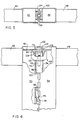
- a draw-tube assembly 94 comprises a rectangular draw tube 96, a draw nut 100 and a threaded shoulder cap screw 102.
- the rectangular draw tube 96 which can be formed by roll-forming, has a number of equally spaced openings 98 and a pair of upwardly directed retaining clips 99.
- the clips 99 can be formed by an extrusion which is inserted into the draw tube in a snap-fit connection.
- the draw nut 100 is U-shaped in elevational view and has upstanding sides 104 with slanted inner wedging surfaces 106. As illustrated in Figure 4, the slanted wedging surfaces 106 define a complementary angle with the wedging surfaces 90 of the reaction plate 80.
- a threaded opening 108 is provided through the center of the draw nut 100.
- An attaching plate 110 projects from the bottom surface of the draw nut and is shaped to fit within the top portion of the draw tube 96. The draw tube 96 is secured to the draw nut 100 through welding or through a mechanical fastening technique at attaching plate 110.
- the threaded shoulder cap screw 102 has a depending threaded shank 112 and a pair of spaced annular shoulders 114 and 116. As illustrated in Figure 4, the shoulders 114 and 116 are spaced a distance so as to receive the outwardly-projecting tongue therebetween, while the shank between the shoulders 114 and 116 fits within the U-shaped slot 86 of the reaction plate 80.
- a pair of U-shaped spring clips 118 have outwardly directed retaining flanges 120 at the ends thereof and retaining projections 122 at the central portions of the side of the clip.
- the spring clips 118 fit within the openings 98 in the draw tube 96 and are retained thereby. Further, the clips project into the lower rectangular opening 76 in the trough bottom wall 60 to releasably hold the draw-tube assembly 94 on the stile.
- the spring clips 118 are not structural in nature but simply serve to hold the draw-tube assembly 94 on the stile 44 during transportation and prior to assembly. Only one set of spring clips 118 is thus provided on each stile and draw tube combination.
- the draw-tube assembly 94 is positioned adjacent the stile 44 with the spring clips 118 entering the rectangular openings 76.
- the engagement fingers 78 will project into the upper and lowermost rectangular openings 98 of the draw tube 96 and an upwardly directed clip 99 will project through the lowermost opening 76 in wall 60.
- a side 104 of the draw nut 100 will project through the upper opening 74 and the threaded shoulder cap screw 102 is adjusted so that the tongue 84 is recieved between the shoulders 114 and 116 of the cap screw 102.
- the other frame is then positioned adjacent the first frame so that the draw tube snugly fits within the U-shaped trough formed in the outside face 56 of the other assembly.
- a clip 99 will project through a lowermost hole 76 in the adjacent wall 60.
- the other side 104 of the draw nut extends through the opening 74 in the trough bottom wall 60 and beneath the depending block 88 of the reaction plate 80.
- the shoulders 114 and 116 of the threaded cap screw 102 again receive the tongue 84 of the reaction plate 80 in the other stile. The threaded cap screw 102 is then rotated so as to draw the draw tube 96 upwardly.
- the threaded cap screw 102 along with the tongue 84 thus form a mechanical advantage adjusting means between the draw-tube wedge means (draw nut 100) and the adjacent frame stiles 44.
- This relative longitudinal movement results in the drawing of the frames tightly together through the interengaging. action of the wedging surfaces 106 and 90 and further as a result of the draw-tube openings 98 passing beneath the engagement fingers 78 as well as the engagement fingers 99 passing upwardly behind the wall 60.
- the lateral force provided between the frames is taken up by the draw nut 100 and the reaction plates 80 and to some extent by the clips 99, and not essentially by the engagement fingers 78.
- the strength and rigidity of the frames are carried through the draw nut 100 and reaction plates 80 and to some extent by the clips 99.
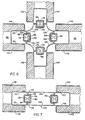
- the panel connection system comprises an extruded elongated hollow connector 130 which preferably is made out of aluminum, having four equally spaced indented channels 132. Retaining lips 134 extend inwardly from the edges of the indented channel 132. Arcuate wall portions 136 connect the indented channels 132. A steel U-shaped channel 138 is mounted within the indented channel 132 and retained therein by the retaining lip 134. Additionally, mechanical fastening means such as a screw (not shown) are provided between the U-shaped channel 138 and the indented channel 132 to prevent relative longitudinal movement therebetween.
- An engagement finger 140 is struck outwardly from the U-shaped channel 138 and extends into the opening 98 in the rectangular draw tube 96.
- the connector 130 thus joins to each of the frames 42 in the same manner as the frames are joined to each other, that is through a draw-tube assembly 94. All of the connections between the frames and the connector 130 are identical and accordingly only one such connection has been discussed. Outsert panels 142 are shown on the outside of the frames 42.
- a three-panel connector similar to the connector illustrated in Figure 6 would be identical with the connector shown in Figure 6 except that one of the indented channels 132 would be absent.
- indented channels 132 can be spaced at different angles with respect to each other, for example at 120° from each other. See, for example, 120° joint 36 in Figure 1.
- FIG 7 there is shown a connection between two frames in spaced-apart relationship.
- This connection may be used where a small space is required due to use of a four- panel connector as illustrated in Figure 6 or a three-panel connector (not shown) at another part of the wall system.
- An extruded elongated hollow connector 150 has a pair of indented channels 152 at either end thereof.
- Retaining lips 154 extend inwardly from the edge of the indented channels 152 to retain the steel U-shaped channels 138 in the same fashion as the connector illustrated in Figure 6.
- Struck engagement fingers 140 extend inwardly from the channel 138 and engage the draw tube 96 in the same fashion as the connector of Figure 6 and in the same fashion as the connector illustrated in Figures 2-5.
- FIG. 8 shows a 90° corner connector using a connection system according to the invention.
- An elongated corner connector 160 has elongated U-shaped channels 162 at either end thereof and spaced 90° from each other.
- Retaining lips 164 extend inwardly from the channels to retain therein U-shaped steel channels 138 which have engagement fingers 140 struck into the channels therefrom.
- the engagement fingers 140 engage draw tubes 96 in the same fashion as the connectors of Figures 2-7.
- An arcuate inner wall 166 and an arcuate outer wall 168 connect the channels 162.
- a connector of similar design can be used to connect two panels together in angular relationships greater than 90, simply by changing the angular relationship between the channels 162.
- the arcuate outer wall 168 has a pair of outward projections 170, each of which has a retaining lip 172 extending laterally from an outer portion thereof.
- a cover 174 is provided for snap-fit connection over the arcuate outer wall 168 for plastic finishing flush with the outsert panels 142.
- the cover can be extruded of any suitable plastic material or can be covered with fabric or vinyl.
- the cover 174 has a curved outer wall 176 and a pair of inwardly directed end walls 178.
- Inwardly- projecting flanges 180 extend inwardly from the inside of the curved outer wall 176 and have engaging lips 182 extending laterally thereof. As illustrated in Figure 8, the retaining lips 172 and 182 engage each other for a snap-fit connection between the curved outer wall 176 and the connector 160.
- FIG. 9 there is shown a connector system for changing height between two wall units. Like numbers are used to describe like parts.
- a modified reaction plate 190 is positioned in the taller of the two stiles in juxtaposition to the reaction plate 80 in the adjacent smaller stile.
- the modified reaction plate 190 can be inserted through an appropriate opening 74 in the wall 60 of the stile and pushed up into place so that an outwardly-projecting tongue 192 of the reaction plate 190 fits through a slotted opening 188 in the wall 60.
- the reaction plate has a wedging surface 194 of identical shape with the wedging surface 90 of the reaction plate 80.
- a threaded opening is provided in the upper part of the reaction plate 190 and a threaded fastener passes through the wall 6 and threadably engages the threaded opening in the reaction plate 190 to secure the reaction plate 190 in position in the wall 60.
- a top cap 198 can be positioned on top of each of the walls to cover the upper portion of the frames.
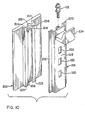
- an end cap 200 and a draw channel 216 are provided.
- the end cap has an interior channel 202 formed by a pair of L-shaped flanges 203.
- a pair of shoulders 204 and 210 are provided at the upper portion of the end cap 200 and each shoulder has U-shaped recesses 208 and 212.
- a pocket 206 is formed between the shoulders 204 and 210.
- the draw channel 216 has an elongated U-shaped frame 218 with spaced elongated openings 220 and a pair of outwardly directed flanges 222.
- a partial draw nut 224 is secured to the upper portion of the frame 218 and has a threaded bore 226 with a leg portion 228 having a wedging surface 230.
- a threaded cap screw 102 is threadably received within the threaded bore 226 of the partial draw nut 224.
- the shoulder 114 of the cap screw 102 is received within the pocket 206 of the end cap 200 while the shank portion below the shoulder 114 is received in the U-shaped recess 208 of the end cap 200.
- the head of the cap screw 102 is received in the U-shaped recess 212 of the end cap 200.
- the cap-screw shoulder 116 is received beneath the shoulder 204 of the end cap 200.
- the leg 228 of the partial draw nut 224 projects through an upper opening 74 in the wall 60 of stile 44 and the wedging surface 230 engages the downwardly-projecting wedging surface 90 of the reaction plate 80.
- finger 78 extends through opening 220 and is received behind the frame 218 as the draw channel 216 is drawn upwardly with respect to the stile 44.
- the flanges 222 fit behind the L-shaped flanges 203 of the end cap and thus the draw channel 216 slides freely within the channel of the end cap 200.
- the end cap 200 is placed in position as illustrated in Figure 9 with the draw channel 216 positioned well below the location illustrated in Figure 9.
- the leg 228 of the partial draw nut 224 projects through the top opening 74 and the clip 78 projects through the opening 220 in the frame 218.
- the cap screw 102 is threaded into the partial draw nut 224 to draw the draw channel 216 upwardly with respect to both the stile 44 and the end cap 200.
- the engagement fingers can be formed on the draw tube 96 and the corresponding openings can be formed on the stiles 44.
- the invention has been described with reference to raising the draw tube to engage the wedging surfaces. The invention can also be carried out by adjusting the draw tube downwardly to engage wedging surfaces reversed in orientation. Further, . the invention has been described with reference to a rectangular draw tube 96 and correspondingly shaped troughs in the outside faces 56 of the stiles 44.
- the draw tube 96 and the indented channel in the outside face 56 can take on other complementary shapes so long as the draw tube fits snugly within the indented channel in the outside face 56 and lateral shear strength is accomplished.
Landscapes
- Engineering & Computer Science (AREA)
- Architecture (AREA)
- Physics & Mathematics (AREA)
- Electromagnetism (AREA)
- Civil Engineering (AREA)
- Structural Engineering (AREA)
- Furniture Connections (AREA)
- Assembled Shelves (AREA)
- Joining Of Corner Units Of Frames Or Wings (AREA)
Description
- This invention relates to a wall system including connectors and panels, each of which has elongate stiles extending the length of opposite ends thereof and having side faces with an edge face therebetween and an indented channel extending along the length of said edge face, elongate tubes positioned within the channels of said stiles and having a cross-sectional shape complementary thereto; interengaging means on the tubes and stiles and including wedge means on the tubes and the stiles, one of the wedge means being adjustable with respect to the other, and mechanical adjusting means for said wedge means to draw adjacent panels together.
- A wall system of this kind is described in FR-A-2 435 572. Its purpose is to join panels by connectors to form walls for open-office work stations. In the known system, panels are connected by tubular traverses arranged in U-shaped channel members at the upper and lower edge of each panel. Both traverses are connected by a tube which is positioned between the vertical edges of the panels at which the channels of the stiles are provided. The tube is provided at its upper and lower end with a bolt which passes through a hole in each traverse, and a nut is provided to secure each traverse at the upper and lower end of the tube, respectively. In this way, the traverses and the tube form a connecting frame in which the panels are held by the tension which is exerted upon the tube by the screw connection with the traverses. The panels are additionally held together by the interengaging means on the tube and the stiles, which comprise wedge means drawing the panels to each other when the screw connections are tightened.
- This prior art wall system has several disadvantages. By its completely symmetrical design, two complete sets of screw connections and wedge means are required. Joining of two panels with such a device is complicated, since the panels must be combined lying on the bottom of the room where they are to be installed and the screw-connections must be completed before the combined panels can be set up in vertical orientation. A further disadvantage consists in that the traverses at the upper and lower edge of the panels must be brought in exact alignment with the tube bolts before the screw connection can be completed. A third disadvantage is the requirement of a cavity at each corner of the panels to get space for the wedge mechanism. Therefore, there will be no direct rigid connection between the vertical and horizontal edge elements of the panels. If the screw connection between the traverses and the tube loosens with time, the stability of the panel connection will be affected. The rigidity of the whole construction of several combined panels is not satisfactory, which will be evident when bending moments are produced by work surfaces, shelves and cabinets hanging from the construction. Such bending moments tend to distort the holding frames out of their plane. A more rigid connection will be possible, if the traverses extend along the entire length of any given framework. By this, however, the combination work will be more complicated and cumbersome. Obviously, the system described in FR-A-2 435 572 does not readily permit flexibility of long strings of panels or strings in which the angular relationship between the panels changes.
- The present invention solves these problems by the features specified in the characterising part of the main claim. Advantageous further developments are described in the dependent claims.
- The invention provides a secure, rigid connection between adjacent frames. The connector has lateral shear strength due to the interrelationship between the tube and the indented channel which makes it possible that the edge faces of adjacent stiles can be tightly drawn together. Horizontal rigidity and strength between panels are provided by the wedge means, the adjustment of which produces a longitudinal movement of the tube with respect to the stiles. By this movement the engagement elements of the interengagement means are brought into a position in which they hold the abutting edge faces of adjacent frame stiles together. The result is that only one adjustment mechanism is required which can be easily provided on the upper portions of the tubes and the stiles, respectively, where also the top members of the panels are provided. Thus, the wedge means can be primarily used for providing a very rigid and strong linear connection along a horizontal axis which runs along the top of the frames as well as a strong bending moment connection. Such a combination of axial and lateral rigidity provides a rigid interlocking framework on which work surfaces, cabinets and shelves can be hung. The panels are quickly and easily assembled by placing a tube assembly within a channel of one edge face of the panel, bringing the other panel edge face in close relationship thereto and tightening the wedge means by the mechanical adjusting device. The connector assembly is economically made by conventional manufacturing techniques. For instance, the tubes and the stiles can be made in conventional roll-forming operation preceded or interspersed with a stamping operation to form interengagement elements which can have the form of openings and engagement fingers.
- The invention will now be described with reference to the accompanying drawings in which:
- Figure 1 is a perspective view of an office layout incorporating frames with connector systems according to the invention;
- Figure 2 is an exploded view of a frame connector system according to the invention;
- Figure 3 is a perspective exploded view of assembled components of frame connector systems shown in Fig. 2;
- Figure 4 is a front elevational view of an assembled frame connector system, partially broken away;
- Figure 5 is a plan view of an assembled connector shown in Figure 4;
- Figure 6 is a horizontal sectional view of four panels joined together at a common axis with a connector system according to the invention;
- Figure 7 is a horizontal sectional view of two panels, joined together in spaced relationship, with a modified connector system according to the invention;
- Figure 8 is a horizontal sectional view of two panels joined together at 90 angles with a connector assembly according to the invention; and
- Figure 9 is a front elevational view 'n section of an assembled frame connector system between two walls of different height, showing a change-of-height connector system; and
- Figure 10 is an exploded perspective view of several components used in the change-of-height connector system illustrated in Figure 9.
- Referring now to the drawings, and to Figure 1 in particular, there is shown an office layout system having a single work
station panel system 12 and a multiple workstation panel system 14. The work stations are formed by selected full-sized walls 16 andshort walls 18. Each of thewalls Work surfaces 20,cabinets 22 andshelves 24 are supported in cantelevered fashion from both the full-sized walls 16 and theshort walls 18.Baseline wiring 26 and belt-line wiring 28 are provided at selected locations along both theshort walls 18 and the full-sized walls 16. The walls are formed bystraight panel sections 30 andcurved panel sections 32. Ninety-degree joints 35,120°joints 36 and T-walljoint connections 38 are formed between various panels as desired. Further, straight-wall connections 39 are formed between both straight-wall and curved-wall sections. Referring now to Figures 2-5, there is shown a straight-wall connection 39, for example, between two straight-wall sections. The wall sections are aligned coaxially to form an integral straight-wall section. The wall sections are formed fromframes 42 and removable outsert panels (not shown) which are removably secured to the frames. Theframes 42 are formed byvertical stiles 44,bottom cross-members 46 andtop cross-members 48, all joined together through welding to form a rigid interlocking rectangular frame. Thestiles 44 are identical and accordingly only one stile will be described. - The
stiles 44 have aside face 50, aninside face 52, which is welded to thebottom cross-member 46 and thetop cross-member 48, aside face 54 and anoutside face 56. A U-shaped trough, formed bytrough side walls 58 andtrough bottom wall 60, extends the length of the stile along theoutside face 56. -
Keyhole slots 62 andrectangular slots 64 are spaced along theside face 50 to releasably retain the outsert panels. An aligned row ofvertical slots 66 is provided at the corner between theside face 50 and theoutside face 56. These vertical slots are used for hanging thework surfaces 20, thecabinets 22 and theshelves 24 from the frames through conventional brackets (not shown). -
Rectangular slots 68 andrectangular slots 70 are spaced along theside face 54. Thekeyhole slots 62 and therectangular slots vertical slots 72 are provided between theside face 54 and theoutside face 56 for hanging of work surfaces, shelves and cabinets through conventional brackets (not shown). - A
top slot 73, an upper rectangular opening 74 and lowerrectangular openings 76 are provided in spaced relationship along thetrough bottom wall 60. A pair of struckengagement fingers 78, each of which has a strengtheningridge 79, are struck outwardly and downwardly from thetrough bottom wall 60. - A
reaction plate 80 has atop plate 82 with an outwardly-projectingtongue 84, the outer end of which forms aU-shaped slot 86 and a dependingblock 88. A wedgingsurface 90 is provided on the outer surface of the dependingblock 88. As illustrated in Figures 3 and 4, the outwardly-projectingtongue 84 extends through thetop slot 73. Thereaction plate 80 is welded at the top plate to thestile 44. - A draw-
tube assembly 94 comprises arectangular draw tube 96, adraw nut 100 and a threadedshoulder cap screw 102. Therectangular draw tube 96, which can be formed by roll-forming, has a number of equally spacedopenings 98 and a pair of upwardly directed retaining clips 99. Theclips 99 can be formed by an extrusion which is inserted into the draw tube in a snap-fit connection. - The
draw nut 100 is U-shaped in elevational view and hasupstanding sides 104 with slanted inner wedging surfaces 106. As illustrated in Figure 4, the slanted wedging surfaces 106 define a complementary angle with the wedging surfaces 90 of thereaction plate 80. A threadedopening 108 is provided through the center of thedraw nut 100. An attachingplate 110 projects from the bottom surface of the draw nut and is shaped to fit within the top portion of thedraw tube 96. Thedraw tube 96 is secured to thedraw nut 100 through welding or through a mechanical fastening technique at attachingplate 110. - The threaded
shoulder cap screw 102 has a depending threadedshank 112 and a pair of spacedannular shoulders shoulders shoulders U-shaped slot 86 of thereaction plate 80. - A pair of U-shaped spring clips 118 have outwardly directed retaining
flanges 120 at the ends thereof and retainingprojections 122 at the central portions of the side of the clip. The spring clips 118 fit within theopenings 98 in thedraw tube 96 and are retained thereby. Further, the clips project into the lowerrectangular opening 76 in thetrough bottom wall 60 to releasably hold the draw-tube assembly 94 on the stile. The spring clips 118 are not structural in nature but simply serve to hold the draw-tube assembly 94 on thestile 44 during transportation and prior to assembly. Only one set of spring clips 118 is thus provided on each stile and draw tube combination. - In operation, the draw-
tube assembly 94 is positioned adjacent thestile 44 with the spring clips 118 entering therectangular openings 76. As thedraw tube 96 fits snugly within the trough in theoutside face 56 of the stile, theengagement fingers 78 will project into the upper and lowermostrectangular openings 98 of thedraw tube 96 and an upwardly directedclip 99 will project through thelowermost opening 76 inwall 60. At the same time, aside 104 of thedraw nut 100 will project through theupper opening 74 and the threadedshoulder cap screw 102 is adjusted so that thetongue 84 is recieved between theshoulders cap screw 102. - The other frame is then positioned adjacent the first frame so that the draw tube snugly fits within the U-shaped trough formed in the
outside face 56 of the other assembly. Aclip 99 will project through alowermost hole 76 in theadjacent wall 60. Further, theother side 104 of the draw nut extends through theopening 74 in thetrough bottom wall 60 and beneath the dependingblock 88 of thereaction plate 80. Theshoulders cap screw 102 again receive thetongue 84 of thereaction plate 80 in the other stile. The threadedcap screw 102 is then rotated so as to draw thedraw tube 96 upwardly. The threadedcap screw 102 along with thetongue 84 thus form a mechanical advantage adjusting means between the draw-tube wedge means (draw nut 100) and theadjacent frame stiles 44. This relative longitudinal movement results in the drawing of the frames tightly together through the interengaging. action of the wedging surfaces 106 and 90 and further as a result of the draw-tube openings 98 passing beneath theengagement fingers 78 as well as theengagement fingers 99 passing upwardly behind thewall 60. However, the lateral force provided between the frames is taken up by thedraw nut 100 and thereaction plates 80 and to some extent by theclips 99, and not essentially by theengagement fingers 78. Thus, the strength and rigidity of the frames are carried through thedraw nut 100 andreaction plates 80 and to some extent by theclips 99. The interlocking relationship betwen thestiles 44 and therectangular draw tube 96 provides exceptional lateral stability and rigidity while thedraw nut 100 andreaction plate 80 connections provide very rigid and strong linear connections along a horizontal axis which runs along the top of the frames as well as a strong bending moment connection. This combination of axial and lateral rigidity connections provides a rigid interlocking framework on which work surfaces, cabinets and shelves can be hung. - Reference is now made to Figure 6 for a description of a connector for four panels which are joined together. Like numbers are used for like elements. The panel connection system comprises an extruded elongated hollow connector 130 which preferably is made out of aluminum, having four equally spaced
indented channels 132. Retaininglips 134 extend inwardly from the edges of theindented channel 132.Arcuate wall portions 136 connect theindented channels 132. A steelU-shaped channel 138 is mounted within theindented channel 132 and retained therein by the retaininglip 134. Additionally, mechanical fastening means such as a screw (not shown) are provided between theU-shaped channel 138 and theindented channel 132 to prevent relative longitudinal movement therebetween. Anengagement finger 140 is struck outwardly from theU-shaped channel 138 and extends into theopening 98 in therectangular draw tube 96. The connector 130 thus joins to each of theframes 42 in the same manner as the frames are joined to each other, that is through a draw-tube assembly 94. All of the connections between the frames and the connector 130 are identical and accordingly only one such connection has been discussed.Outsert panels 142 are shown on the outside of theframes 42. - A three-panel connector similar to the connector illustrated in Figure 6 (see T-
wall connection 38 in Figure 1) would be identical with the connector shown in Figure 6 except that one of theindented channels 132 would be absent. In addition, when less than four channels are provided in a connector,indented channels 132 can be spaced at different angles with respect to each other, for example at 120° from each other. See, for example, 120° joint 36 in Figure 1. - Referring now to Figure 7, there is shown a connection between two frames in spaced-apart relationship. This connection may be used where a small space is required due to use of a four- panel connector as illustrated in Figure 6 or a three-panel connector (not shown) at another part of the wall system. An extruded elongated
hollow connector 150 has a pair ofindented channels 152 at either end thereof. Retaininglips 154 extend inwardly from the edge of theindented channels 152 to retain the steelU-shaped channels 138 in the same fashion as the connector illustrated in Figure 6.Struck engagement fingers 140 extend inwardly from thechannel 138 and engage thedraw tube 96 in the same fashion as the connector of Figure 6 and in the same fashion as the connector illustrated in Figures 2-5. - Reference is now made to Figure 8 which shows a 90° corner connector using a connection system according to the invention. Like numerals are used to describe like elements. An
elongated corner connector 160 has elongatedU-shaped channels 162 at either end thereof and spaced 90° from each other. Retaininglips 164 extend inwardly from the channels to retain thereinU-shaped steel channels 138 which haveengagement fingers 140 struck into the channels therefrom. Theengagement fingers 140 engagedraw tubes 96 in the same fashion as the connectors of Figures 2-7. An arcuateinner wall 166 and an arcuateouter wall 168 connect thechannels 162. - A connector of similar design can be used to connect two panels together in angular relationships greater than 90, simply by changing the angular relationship between the
channels 162. - The arcuate
outer wall 168 has a pair ofoutward projections 170, each of which has a retaininglip 172 extending laterally from an outer portion thereof. Acover 174 is provided for snap-fit connection over the arcuateouter wall 168 for plastic finishing flush with theoutsert panels 142. The cover can be extruded of any suitable plastic material or can be covered with fabric or vinyl. Thecover 174 has a curved outer wall 176 and a pair of inwardly directedend walls 178. Inwardly- projectingflanges 180 extend inwardly from the inside of the curved outer wall 176 and have engaginglips 182 extending laterally thereof. As illustrated in Figure 8, the retaininglips connector 160. - Referring now to Figures 9 and 10, there is shown a connector system for changing height between two wall units. Like numbers are used to describe like parts.
- A modified
reaction plate 190 is positioned in the taller of the two stiles in juxtaposition to thereaction plate 80 in the adjacent smaller stile. The modifiedreaction plate 190 can be inserted through anappropriate opening 74 in thewall 60 of the stile and pushed up into place so that an outwardly-projectingtongue 192 of thereaction plate 190 fits through a slottedopening 188 in thewall 60. The reaction plate has a wedgingsurface 194 of identical shape with the wedgingsurface 90 of thereaction plate 80. A threaded opening is provided in the upper part of thereaction plate 190 and a threaded fastener passes through the wall 6 and threadably engages the threaded opening in thereaction plate 190 to secure thereaction plate 190 in position in thewall 60. - The stiles of adjacent walls are secured together with a
draw nut 100 and threadedshoulder cap screw 102 in the same fashion as described above with respect to the wall units of equal height described above with respect to Figures 2-4. The same rigidity between the adjacent frames is provided by this change-of-height connection as in the connection between walls of equal height. Atop cap 198 can be positioned on top of each of the walls to cover the upper portion of the frames. - In order to cover the exposed stile above the shorter wall, an
end cap 200 and adraw channel 216 are provided. The end cap has aninterior channel 202 formed by a pair of L-shapedflanges 203. A pair ofshoulders end cap 200 and each shoulder hasU-shaped recesses pocket 206 is formed between theshoulders - The
draw channel 216 has an elongatedU-shaped frame 218 with spacedelongated openings 220 and a pair of outwardly directedflanges 222. Apartial draw nut 224 is secured to the upper portion of theframe 218 and has a threadedbore 226 with aleg portion 228 having a wedgingsurface 230. - As illustrated in Figure 9, a threaded
cap screw 102 is threadably received within the threaded bore 226 of thepartial draw nut 224. Theshoulder 114 of thecap screw 102 is received within thepocket 206 of theend cap 200 while the shank portion below theshoulder 114 is received in theU-shaped recess 208 of theend cap 200. In like manner, the head of thecap screw 102 is received in theU-shaped recess 212 of theend cap 200. The cap-screw shoulder 116 is received beneath theshoulder 204 of theend cap 200. - The
leg 228 of thepartial draw nut 224 projects through anupper opening 74 in thewall 60 ofstile 44 and the wedgingsurface 230 engages the downwardly-projectingwedging surface 90 of thereaction plate 80. Further,finger 78 extends throughopening 220 and is received behind theframe 218 as thedraw channel 216 is drawn upwardly with respect to thestile 44. It should be noted that theflanges 222 fit behind the L-shapedflanges 203 of the end cap and thus thedraw channel 216 slides freely within the channel of theend cap 200. Thus, theend cap 200 is placed in position as illustrated in Figure 9 with thedraw channel 216 positioned well below the location illustrated in Figure 9. Theleg 228 of thepartial draw nut 224 projects through thetop opening 74 and theclip 78 projects through theopening 220 in theframe 218. Thecap screw 102 is threaded into thepartial draw nut 224 to draw thedraw channel 216 upwardly with respect to both thestile 44 and theend cap 200. - Whereas the invention has been described with reference to engagement fingers on the
stiles 44 and corresponding openings in thedraw tube 96, the engagement fingers can be formed on thedraw tube 96 and the corresponding openings can be formed on thestiles 44. Further, the invention has been described with reference to raising the draw tube to engage the wedging surfaces. The invention can also be carried out by adjusting the draw tube downwardly to engage wedging surfaces reversed in orientation. Further, . the invention has been described with reference to arectangular draw tube 96 and correspondingly shaped troughs in the outside faces 56 of thestiles 44. In a broader aspect of the invention, thedraw tube 96 and the indented channel in theoutside face 56 can take on other complementary shapes so long as the draw tube fits snugly within the indented channel in theoutside face 56 and lateral shear strength is accomplished.
Claims (14)
Applications Claiming Priority (2)
| Application Number | Priority Date | Filing Date | Title |
|---|---|---|---|
| US641189 | 1984-08-15 | ||
| US06/641,189 US4571907A (en) | 1984-08-15 | 1984-08-15 | Frame connector system |
Publications (2)
| Publication Number | Publication Date |
|---|---|
| EP0177639A1 EP0177639A1 (en) | 1986-04-16 |
| EP0177639B1 true EP0177639B1 (en) | 1988-10-12 |
Family
ID=24571309
Family Applications (1)
| Application Number | Title | Priority Date | Filing Date |
|---|---|---|---|
| EP84114733A Expired EP0177639B1 (en) | 1984-08-15 | 1984-12-04 | Wall system |
Country Status (4)
| Country | Link |
|---|---|
| US (1) | US4571907A (en) |
| EP (1) | EP0177639B1 (en) |
| CA (1) | CA1237867A (en) |
| DE (1) | DE3474578D1 (en) |
Families Citing this family (52)
| Publication number | Priority date | Publication date | Assignee | Title |
|---|---|---|---|---|
| US4876835A (en) * | 1984-09-10 | 1989-10-31 | Herman Miller, Inc. | Work space management system |
| US4716699A (en) * | 1986-01-17 | 1988-01-05 | Rostec Industries | Wall panels with single load-bearing connector posts |
| US4716692A (en) * | 1986-12-30 | 1988-01-05 | Alma Desk Company | Locking system for interconnecting panels |
| US4914873A (en) * | 1987-03-05 | 1990-04-10 | Herman Miller, Inc. | Work environment system |
| JPH0684643B2 (en) * | 1987-03-14 | 1994-10-26 | コクヨ株式会社 | Movable partition wall |
| USD318582S (en) | 1988-06-10 | 1991-07-30 | Herman Miller, Inc. | Cabinet |
| US5106173A (en) * | 1988-06-10 | 1992-04-21 | Herman Miller, Inc. | Work space management system and cabinet therefor |
| US6497075B1 (en) | 1988-07-29 | 2002-12-24 | Herman Miller Inc. | Free standing modular architectural beam system |
| US5394658A (en) | 1988-07-29 | 1995-03-07 | Schreiner; Charles P. | Free standing modular furniture and wall system |
| US5524402A (en) * | 1988-11-16 | 1996-06-11 | Sykes; Christopher C. | Partition structures and frame elements therefor |
| US5062246A (en) * | 1988-11-16 | 1991-11-05 | Sykes Christopher C | Partition structures and frame elements therefor |
| US5020678A (en) * | 1989-06-27 | 1991-06-04 | Unarco Industries, Inc. | Structural rack |
| USD329875S (en) | 1989-09-05 | 1992-09-29 | Steelcase Inc. | Vertically-mountable, plural-level paper tray |
| USD331164S (en) | 1989-10-23 | 1992-11-24 | Steelcase Inc. | Table |
| US5058347A (en) * | 1990-09-18 | 1991-10-22 | Herman Miller, Inc. | Panel connector system |
| USD336191S (en) | 1992-01-15 | 1993-06-08 | Steelcase Inc. | Combined table top and supports |
| USD343084S (en) | 1992-01-15 | 1994-01-11 | Steelcase Inc. | Top for furniture |
| AT398271B (en) * | 1992-02-05 | 1994-11-25 | Seebach Metallwaren | Profiled strip system |
| AT400390B (en) * | 1992-02-05 | 1995-12-27 | Seebach Metallwaren | Profiled strip system |
| USD336185S (en) | 1992-06-15 | 1993-06-08 | Steelcase Inc. | Table |
| DE9211330U1 (en) * | 1992-08-21 | 1993-02-18 | Aurich, Winfried, O-8060 Dresden | Flexible, universal wooden construction element, especially for the construction of room cells and assembly furniture |
| US5743055A (en) * | 1996-06-04 | 1998-04-28 | Hon Industries Inc. | Wall panel connector system |
| US6167665B1 (en) | 1996-06-07 | 2001-01-02 | Herman Miller, Inc. | Corner post for a wall panel system |
| US6341457B1 (en) | 1996-06-07 | 2002-01-29 | Herman Miller, Inc. | Light seal assembly for a wall panel system |
| US6223485B1 (en) | 1996-06-07 | 2001-05-01 | Herman Miller, Inc. | Wall panel system |
| US5806258A (en) * | 1996-06-07 | 1998-09-15 | Haworth, Inc. | Wall panel system |
| US5852904A (en) * | 1996-08-05 | 1998-12-29 | Haworth, Inc. | Panel arrangement |
| CA2198829A1 (en) * | 1997-02-28 | 1998-08-28 | Global Upholstery Company | Lightweight panel structure |
| AT405747B (en) * | 1997-05-13 | 1999-11-25 | Scheicher Rudolf Michael | Device for fastening wall elements on one another and on supports |
| GB2327996A (en) * | 1997-08-05 | 1999-02-10 | Creative Products Ltd | Joining system for modular office screens |
| JP2002523658A (en) * | 1998-08-27 | 2002-07-30 | ロバート テューブナー | Room splitting equipment for creating workspaces and offices |
| US6115977A (en) * | 1998-09-11 | 2000-09-12 | Krueger International, Inc. | Knock-down panel partition system |
| US6112485A (en) * | 1998-11-04 | 2000-09-05 | Haworth, Inc. | Post-panel connector arrangement |
| US6230459B1 (en) | 1998-12-04 | 2001-05-15 | Steelcase Development Inc. | Wall start for panel systems |
| CA2310548A1 (en) | 1999-06-04 | 2000-12-04 | Herman Miller, Inc. | Stackable wall panel system |
| GB2353541B (en) | 1999-06-04 | 2003-10-15 | Miller Herman Inc | Stackable wall panel system |
| US6718717B2 (en) | 2000-02-25 | 2004-04-13 | Herman Miller Inc. | Modular wall panel and mounting member |
| US6711871B2 (en) | 2000-05-03 | 2004-03-30 | Herman Miller, Inc. | Wall panel with off-module components |
| US6729085B2 (en) | 2001-02-09 | 2004-05-04 | Herman Miller, Inc. | Wall panel system |
| US6684929B2 (en) * | 2002-02-15 | 2004-02-03 | Steelcase Development Corporation | Panel system |
| US7178300B2 (en) * | 2002-09-30 | 2007-02-20 | Krueger International, Inc. | Latch-type tile mounting system |
| US6759589B1 (en) * | 2003-04-23 | 2004-07-06 | Panduit Corp. | Raceway system for office furniture |
| GB2421963B (en) * | 2005-01-11 | 2010-04-07 | Roger Payn | A screen system |
| WO2006092156A1 (en) * | 2005-03-03 | 2006-09-08 | Hoffmann Dienstleistungen für die werbende Wirtschaft GmbH | Wall element |
| US20070125016A1 (en) * | 2005-11-18 | 2007-06-07 | Shawn Yu | Wall panel with corner-connected open frame |
| US7958683B2 (en) * | 2007-10-04 | 2011-06-14 | Hni Corporation | Wall panel system |
| US20090193735A1 (en) * | 2008-01-31 | 2009-08-06 | Ramon Kalinowski | Shear lock modular building panel assembly |
| CA2932539C (en) * | 2016-02-10 | 2025-09-16 | Dirtt Environmental Solutions, Ltd. | Slidable snap-in trim system |
| GB2589262B (en) * | 2016-03-24 | 2021-12-29 | The Wall Top Alarm Company Ltd | Methods and Apparatus for Wall Construction |
| US10973321B2 (en) * | 2018-09-04 | 2021-04-13 | Steelcase Inc. | Workspace system and components and method for the use thereof |
| US11299897B1 (en) * | 2019-01-17 | 2022-04-12 | Shane L. Saia | Apparatus, system, and method for assembling, aligning, leveling, and squaring in-ground pool walls |
| WO2021039411A1 (en) * | 2019-08-30 | 2021-03-04 | 積水ハウス株式会社 | Partitioning storage rack and building |
Family Cites Families (19)
| Publication number | Priority date | Publication date | Assignee | Title |
|---|---|---|---|---|
| US27215A (en) * | 1860-02-21 | Island | ||
| US3312025A (en) * | 1961-05-08 | 1967-04-04 | Katherine M Griffin | Partition construction |
| FR82442E (en) * | 1962-10-12 | 1964-02-07 | Metal partition | |
| USRE27215E (en) | 1966-02-09 | 1971-11-02 | Space divider system | |
| US3430997A (en) * | 1967-05-17 | 1969-03-04 | Miller Herman Inc | Panel joint |
| US3777434A (en) * | 1971-04-26 | 1973-12-11 | Weyerhaeuser Co | Connector |
| US3877191A (en) * | 1974-05-07 | 1975-04-15 | Westinghouse Electric Corp | Connector assembly and support post |
| US3987836A (en) * | 1975-02-19 | 1976-10-26 | Standard Desk Limited | Screen partition assembly |
| US4047342A (en) * | 1975-05-05 | 1977-09-13 | Paul Boulva | Panel assembly |
| US3987838A (en) * | 1975-08-04 | 1976-10-26 | The Glen O'brien Movable Partition Co., Inc. | Partition system |
| US4129163A (en) * | 1975-09-17 | 1978-12-12 | The Haws Corporation | Panel assembly and components thereof |
| US4104838A (en) * | 1977-05-17 | 1978-08-08 | Gf Business Equipment, Inc. | Portable wall assembly |
| US4232183A (en) * | 1977-08-29 | 1980-11-04 | Person Nelson H | Electrical connection system for panel structures |
| US4438614A (en) * | 1978-03-02 | 1984-03-27 | Hauserman, Inc. | Demountable interior partition system and components therefor |
| DE7921206U1 (en) * | 1978-08-08 | 1979-11-22 | Intercamp S.P.A., Volvera, Turin (Italien) | PRE-FABRICATED WALL FROM PREFABRICATED MODULAR UNITS |
| NL8002776A (en) * | 1980-05-13 | 1981-12-16 | Meubelbedrijf Homburg B V | Exhibition stand building panel - has strips between layers engaged by locking device holding adjacent panels together |
| US4430838A (en) * | 1980-08-07 | 1984-02-14 | Westinghouse Electric Corp. | Panel joints |
| US4334374A (en) * | 1981-03-26 | 1982-06-15 | The Mead Corporation | Means for attaching a panel to an upright |
| FR2535572A1 (en) * | 1982-10-29 | 1984-05-04 | Thomson Brandt | APPARATUS USING A RETRACTABLE MICROPHONE |
-
1984
- 1984-08-15 US US06/641,189 patent/US4571907A/en not_active Ceased
- 1984-12-04 EP EP84114733A patent/EP0177639B1/en not_active Expired
- 1984-12-04 DE DE8484114733T patent/DE3474578D1/en not_active Expired
- 1984-12-28 CA CA000471186A patent/CA1237867A/en not_active Expired
Also Published As
| Publication number | Publication date |
|---|---|
| US4571907A (en) | 1986-02-25 |
| DE3474578D1 (en) | 1988-11-17 |
| CA1237867A (en) | 1988-06-14 |
| EP0177639A1 (en) | 1986-04-16 |
Similar Documents
| Publication | Publication Date | Title |
|---|---|---|
| US4571907A (en) | Frame connector system | |
| USRE32890E (en) | Frame connector system | |
| US4833848A (en) | Double panel assembly | |
| US5321924A (en) | Wall assembly | |
| US3425171A (en) | Space divider system | |
| US4074489A (en) | Wall panel assembly | |
| US4493172A (en) | Connector system | |
| US4120124A (en) | Movable wall assembly | |
| US3057444A (en) | Tubular mullion snapon assembly | |
| US5694729A (en) | Wall partition connector | |
| US5067294A (en) | Partition assembly | |
| JPH04228749A (en) | Office space dividing system | |
| US20120042593A1 (en) | Structural top cap arrangement for wall panel | |
| US4580373A (en) | Building element and roof structure comprising a plurality of such elements | |
| US4570402A (en) | Connector apparatus for modular panel structure | |
| US3925939A (en) | Support structure for shelving | |
| US3714748A (en) | Support structure for shelving | |
| GB1587379A (en) | Framing system | |
| EP0570374A1 (en) | Framework of partition walls | |
| US20020185640A1 (en) | Post and coupling combination | |
| US4183185A (en) | Prefabricated modular building | |
| US20020020140A1 (en) | Interconnectable studs and tracks for a building system | |
| EP0333463B1 (en) | Panel edge strips | |
| EP0093131A1 (en) | Arrangement in a roller conveyor or a conveyor belt | |
| JP2000129827A (en) | Connecting device for partition panel |
Legal Events
| Date | Code | Title | Description |
|---|---|---|---|
| PUAI | Public reference made under article 153(3) epc to a published international application that has entered the european phase |
Free format text: ORIGINAL CODE: 0009012 |
|
| AK | Designated contracting states |
Kind code of ref document: A1 Designated state(s): DE FR GB |
|
| 17P | Request for examination filed |
Effective date: 19860919 |
|
| 17Q | First examination report despatched |
Effective date: 19870619 |
|
| GRAA | (expected) grant |
Free format text: ORIGINAL CODE: 0009210 |
|
| AK | Designated contracting states |
Kind code of ref document: B1 Designated state(s): DE FR GB |
|
| REF | Corresponds to: |
Ref document number: 3474578 Country of ref document: DE Date of ref document: 19881117 |
|
| ET | Fr: translation filed | ||
| PLBE | No opposition filed within time limit |
Free format text: ORIGINAL CODE: 0009261 |
|
| STAA | Information on the status of an ep patent application or granted ep patent |
Free format text: STATUS: NO OPPOSITION FILED WITHIN TIME LIMIT |
|
| 26N | No opposition filed | ||
| REG | Reference to a national code |
Ref country code: GB Ref legal event code: IF02 |
|
| PGFP | Annual fee paid to national office [announced via postgrant information from national office to epo] |
Ref country code: GB Payment date: 20031112 Year of fee payment: 20 |
|
| PGFP | Annual fee paid to national office [announced via postgrant information from national office to epo] |
Ref country code: FR Payment date: 20031218 Year of fee payment: 20 |
|
| PGFP | Annual fee paid to national office [announced via postgrant information from national office to epo] |
Ref country code: DE Payment date: 20040130 Year of fee payment: 20 |
|
| PG25 | Lapsed in a contracting state [announced via postgrant information from national office to epo] |
Ref country code: GB Free format text: LAPSE BECAUSE OF EXPIRATION OF PROTECTION Effective date: 20041203 |
|
| REG | Reference to a national code |
Ref country code: GB Ref legal event code: PE20 |