EP0177402B1 - Grinding machines for spectacle glasses - Google Patents
Grinding machines for spectacle glasses Download PDFInfo
- Publication number
- EP0177402B1 EP0177402B1 EP19850401840 EP85401840A EP0177402B1 EP 0177402 B1 EP0177402 B1 EP 0177402B1 EP 19850401840 EP19850401840 EP 19850401840 EP 85401840 A EP85401840 A EP 85401840A EP 0177402 B1 EP0177402 B1 EP 0177402B1
- Authority
- EP
- European Patent Office
- Prior art keywords
- axis
- rotation
- machine
- lens
- extension
- Prior art date
- Legal status (The legal status is an assumption and is not a legal conclusion. Google has not performed a legal analysis and makes no representation as to the accuracy of the status listed.)
- Expired
Links
Images

Classifications
-
- B—PERFORMING OPERATIONS; TRANSPORTING
- B24—GRINDING; POLISHING
- B24B—MACHINES, DEVICES, OR PROCESSES FOR GRINDING OR POLISHING; DRESSING OR CONDITIONING OF ABRADING SURFACES; FEEDING OF GRINDING, POLISHING, OR LAPPING AGENTS
- B24B9/00—Machines or devices designed for grinding edges or bevels on work or for removing burrs; Accessories therefor
- B24B9/02—Machines or devices designed for grinding edges or bevels on work or for removing burrs; Accessories therefor characterised by a special design with respect to properties of materials specific to articles to be ground
- B24B9/06—Machines or devices designed for grinding edges or bevels on work or for removing burrs; Accessories therefor characterised by a special design with respect to properties of materials specific to articles to be ground of non-metallic inorganic material, e.g. stone, ceramics, porcelain
- B24B9/08—Machines or devices designed for grinding edges or bevels on work or for removing burrs; Accessories therefor characterised by a special design with respect to properties of materials specific to articles to be ground of non-metallic inorganic material, e.g. stone, ceramics, porcelain of glass
- B24B9/14—Machines or devices designed for grinding edges or bevels on work or for removing burrs; Accessories therefor characterised by a special design with respect to properties of materials specific to articles to be ground of non-metallic inorganic material, e.g. stone, ceramics, porcelain of glass of optical work, e.g. lenses, prisms
- B24B9/144—Machines or devices designed for grinding edges or bevels on work or for removing burrs; Accessories therefor characterised by a special design with respect to properties of materials specific to articles to be ground of non-metallic inorganic material, e.g. stone, ceramics, porcelain of glass of optical work, e.g. lenses, prisms the spectacles being used as a template
Definitions
- the present invention relates to the cutting of spectacle lenses, and it relates more particularly to the production of left and right lenses for the same frame from a single measurement reading of the right eye or the left eye.
- the conventional machines currently used for cutting spectacle lenses include a rotary grinding wheel comprising a groove usually of V-shaped section in which the edge of the blank to be cut rests.
- This blank is carried by an axis parallel to that of the grinding wheel, between the branches of a U-shaped carriage mounted oscillating and sliding on an axis also parallel to that of the grinding wheel.
- a template can be mounted on the axis carrying the blank and abuts on a key.
- the object of the invention is to provide conventional machines with a single carriage moving around an axis an improvement allowing them to produce symmetrical glasses, either using a template, or without a template by means of a copying machine.
- the axis of rotation 0 of the glass A moves along a curve C around the axis B of the carriage D.
- a machine To overcome this drawback, a machine must be used having two carriages D1, D2 moving around two axes B1, B2 parallel and symmetrical with respect to the axis M of the grinding wheel.
- the invention aims to achieve a grinding machine template or copious single carriage moving around an axis and comprising a device for cutting symmetrical glasses by simply reversing the direction of rotation of the glass.
- a machine for grinding spectacle lenses of the type comprising a circular grinding wheel, a carriage moving around an axis and carrying means for fixing the lens on an axis of rotation parallel to that of the grinding wheel and a sensor for controlling the glass rotation drive, characterized in that said sensor is fixed to an elongated member mounted to oscillate and slide at one end on the axis of the grinding wheel, on the one hand, its other end without clearance surrounding the axis of rotation of the glass, on the other hand.
- the senor mounted on said member follows the movement of a straight line connecting the axis of rotation of the glass to that of the grinding wheel and thus constituting an axis of symmetry of machining identical to that of a grinding machine. having a straight-moving carriage.
- said member in the case of a machine provided with a copying machine, carries at least one sensor whose signals are used to control the axis of rotation of the lens relative to that of the frame and ensuring synchronism between the rotation of the lens and that of the frame.
- the key or stop thereof is mounted to oscillate and coaxial with said member, the latter comprising means for guiding said key.
- said member of elongated shape, comprises at one end an eye in which freely rotates an extension of the axis of rotation of the glass and at its opposite end a longitudinal slot through which s 'extends an extension of the axis of the grinding wheel, the center of said eye being located on the extension of the axis of the slot.
- the body of the key, or stop of the template is articulated on said extension of the axis of the grinding wheel and said guide means are constituted by two fingers projecting from said member and between which extends the body of the key .
- Figure 1 is a partial schematic view showing the contact points on the grinding wheel of two symmetrical glasses on a machine having a carriage moving in a plane.
- Figure 2 is a view similar to that of Figure 1 with a machine having a carriage moving about an axis.
- Figure 3 is a view similar to that of Figures 1 and 2, with a machine having two symmetrical carriages.
- Figure 4 is an end view of a machine having a single carriage moving about an axis.
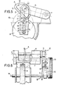
- Figure 5 is a schematic end view of a machine having a single carriage moving around an axis and using a template.
- Figure 6 is a schematic side elevational view of the machine of Figure 5 showing the mounting of the member carrying the sensors and the template key.
- Figure 1 shows the axis of symmetry of machining XX on a grinding machine having a carriage moving in a plane containing the axis 0 of rotation of the glass and the axis M of grinding wheel rotation.
- FIG. 2 shows the curve C described by the axis 0 and shows the deviation thereof relative to the axis X-X.
- FIG. 3 shows the symmetry obtained with a machine with two carriages moving around axes parallel to that of the grinding wheel and symmetrical with respect thereto.
- Figure 4 a view similar to that of Figure 2 of an improved machine according to the invention and comprising for this purpose a member 1 of elongated shape having at one end a head having an eye 2 surrounding an extension 3 of the axis 0 of rotation of the glass, which turns freely but without play in this eye 2.
- the member 1 has an elongated longitudinal slot 4 through which extends an extension 5 of the axis M of rotation of the grinding wheel, the center of the eye 2 is located on the extension of the slot axis 4.
- the straight line OM is always perpendicular to the straight line joining the points of contact a, a ', with the grinding wheel and therefore constitutes the equivalent of that shown in FIG. 1. obtained with a carriage with rectilinear displacement and can by therefore be used as a reference line and as a machining symmetry axis.
- the rotation of the glass is measured, from a radius-origin chosen on the glass, with respect to this reference line.
- sensors such as 6 fixed on the member 1 so as to coincide with the straight line OM. These sensors are used to display the dimension calculated between the axes O and M, and to control the axis of rotation of the lens with respect to the axis of rotation of the frame, in the case where the grinding machine is provided with a copious.
- FIGS. 5 and 6 show an example of application of the invention to a machine of the same type, but using a template.
- the carriage D As shown in Figures 5 and 6, the carriage D, U-shaped, is movable about an axis 7 and carries means for fixing a glass A on an axis of rotation O.
- the axis 0 has an extension 3 which extends outside the carriage D.
- the grinding wheel 8 is rotatably mounted around the axis parallel to the axis 0, which has an extension 5 extending in the same direction as the extension 3 of the axis O.
- An elongate member 1 has at one end a head having an eye 2 which freely, but without play, surrounds the extension 3 of the axis 0, and at its opposite end a longitudinal slot 4 having a width equal to the diameter of the extension 5 so that the member 1 can slide thereon.
- the center of the eye 2 is located on the longitudinal axis of the slot 4.
- the member 1 comprises, in the vicinity of its middle part, guide means constituted for example by two parallel fingers 9 spaced apart.
- the longitudinal axis of the template is also made integral with the reference line OM.
- the button 11 of the template 12 is adjustable in height by means of a conventional rack and pin device 13.
- the improved machine according to the invention allows not only the size of the symmetrical glasses by a simple reversal of the direction of rotation of the glass, as well in the case of a copying machine than in that of a template machine, but also the size of a glass smaller or larger than the measurement record, without any offset of the glass.
Description
La présente invention est relative au taillage des verres de lunettes, et elle concerne plus particulièrement la réalisation des verres gauche et droit pour une même monture à partir d'un seul relevé de mesure de I'œil droit ou de l'ceil gauche.The present invention relates to the cutting of spectacle lenses, and it relates more particularly to the production of left and right lenses for the same frame from a single measurement reading of the right eye or the left eye.
Les machines classiques actuellement utilisées pour tailler les verres de lunettes comprennent une meule rotative comportant une gorge habituellement de section en V dans laquelle vient reposer le bord de l'ébauche à tailler.The conventional machines currently used for cutting spectacle lenses include a rotary grinding wheel comprising a groove usually of V-shaped section in which the edge of the blank to be cut rests.
Cette ébauche est portée par un axe parallèle à celui de la meule, entre les branches d'un chariot en U monté oscillant et coulissant sur un axe également parallèle à celui de la meule.This blank is carried by an axis parallel to that of the grinding wheel, between the branches of a U-shaped carriage mounted oscillating and sliding on an axis also parallel to that of the grinding wheel.
Un gabarit peut être monté sur l'axe portant l'ébauche et vient buter sur une touche.A template can be mounted on the axis carrying the blank and abuts on a key.
On rencontre actuellement des problèmes lorsqu'on désire procéder au taillage d'un verre symétrique d'un premier verre déjà taillé. En effet, il n'est pas possible de procéder par simple retournement du verre, en raison de ce que les meules utilisées pour tailler les biseaux ne sont pas symétriques et du fait que la sphéricité du verre impose au contour de celui-ci une position différente lorsqu'on le retourne.Problems are currently encountered when it is desired to cut a symmetrical glass from a first glass already cut. Indeed, it is not possible to proceed by simple inversion of the glass, due to the fact that the grinding wheels used to cut the bevels are not symmetrical and to the fact that the sphericity of the glass imposes on the contour of the latter a position different when turned over.
Il est en conséquence nécessaire de retourner le gabarit, ce qui constitue un inconvénient, et il est apparu souhaitable de supprimer cette opération.It is therefore necessary to return the template, which is a drawback, and it appeared desirable to eliminate this operation.
Dans le cas où l'on désire ne pas utiliser de gabarit (machine à copieuse), il est alors nécessaire d'utiliser une "machine d'un type différent dont le chariot se déplace de façon rectiligne dans un plan, les verres gauche et droit étant taillés l'un après l'autre en changeant le sens de rotation du verre par rapport au sens du relevé de mesures effectué sur la monture par le palpeur de la copieuse.If it is desired not to use a template (copying machine), it is then necessary to use a "machine of a different type, the carriage of which moves rectilinearly in one plane, the left glasses and straight being cut one after the other by changing the direction of rotation of the lens in relation to the direction of the measurement taken on the frame by the feeler of the copier.
Il existe également des machines à copieuse, à deux chariots opposés montés oscillants sur deux axes parallèles entre eux et à l'axe de la meule, de part et d'autre de ce dernier. Dans ce cas on utilise un sens de rotation différent du verre sur chaque chariot pour obtenir les verres symétriques.There are also copying machines, with two opposite carriages mounted oscillating on two axes parallel to each other and to the axis of the grinding wheel, on either side of the latter. In this case, a different direction of rotation of the glass is used on each carriage to obtain the symmetrical glasses.
Le but de l'invention est d'apporter aux machines classiques à un seul chariot se déplaçant autour d'un axe un perfectionnement leur permettant de réaliser des verres symétriques, soit en utilisant un gabarit, soit sans gabarit au moyen d'une copieuse.The object of the invention is to provide conventional machines with a single carriage moving around an axis an improvement allowing them to produce symmetrical glasses, either using a template, or without a template by means of a copying machine.
On a représenté schématiquement au dessin le déplacement de l'axe de rotation d'un verre de lunette sur une machine à chariot se déplaçant dans un plan (figure 1) et sur des machines à chariot se déplaçant autour d'un axe (figures 2 et 3).The movement of the axis of rotation of a spectacle lens is shown diagrammatically in the drawing on a carriage machine moving in a plane (figure 1) and on carriage machines moving around an axis (figures 2 and 3).
Comme on le voit clairement à la figure 1, dans le cas d'une machine à chariot se déplaçant dans un plan X-X l'axe de rotation 0 du verre et l'axe de rotation M de la meule sont situés dans ce plan.As can be clearly seen in Figure 1, in the case of a carriage machine moving in a plane X-X the axis of rotation 0 of the glass and the axis of rotation M of the grinding wheel are located in this plane.
Par suite, si on retourne le verre A dans la même position angulaire mais opposée A', ce verre sera en contact avec deux points de la meule a et a' équidistants du plan X-X, c'est-à-dire de la droite OM reliant l'axe de rotation du verre à celui de la meule.Consequently, if the glass A is returned to the same angular but opposite position A ', this glass will be in contact with two points of the grinding wheel a and a' equidistant from the plane XX, that is to say from the line OM connecting the axis of rotation of the glass to that of the grinding wheel.
Dans le cas d'une machine à chariot se déplaçant autour d'un axe, comme représenté à la figure 2, l'axe de rotation 0 du verre A se déplace suivant une courbe C autour de l'axe B du chariot D.In the case of a carriage machine moving around an axis, as shown in FIG. 2, the axis of rotation 0 of the glass A moves along a curve C around the axis B of the carriage D.
Par conséquent, si on retourne le verre A dans la même position angulaire mais opposée A' les points de contact a, a' avec la meule sont déplacés suivant des courbes concentriques à la courbe C, ce qui fausse les mesures données par le gabarit, ou par le palpeur du drageoir dans le cas d'une copieuse, lorsqu'on retourne le verre.Consequently, if we return the glass A to the same angular position but opposite A 'the points of contact a, a' with the grinding wheel are displaced in curves concentric with curve C, which distorts the measurements given by the template, or by the feeler probe in the case of a copious, when the glass is turned over.
Pour remédier à cet inconvénient on doit utiliser une machine ayant deux chariots D1, D2 se déplaçant autour de deux axes B1, B2 parallèles et symétriques par rapport à l'axe M de la meule.To overcome this drawback, a machine must be used having two carriages D1, D2 moving around two axes B1, B2 parallel and symmetrical with respect to the axis M of the grinding wheel.
Lorsqu'on retourne le verre A dans la position A' on le monte sur l'axe de rotation 02 du chariot D2 et les courbes C1 et C2 suivies par les axes de rotation 01 et 02 des deux chariots sont symétriques ainsi que, par suite, les points de contact a et a' sur la meule.When the glass A is returned to position A ′, it is mounted on the axis of rotation 02 of the carriage D2 and the curves C1 and C2 followed by the axes of rotation 01 and 02 of the two carriages are symmetrical so that, consequently , the contact points a and a 'on the grinding wheel.
L'invention a pour but de réaliser une machine à meuler à gabarit ou à copieuse à chariot unique se déplaçant autour d'un axe et comportant un dispositif permettant de tailler des verres symétriques par simple inversion du sens de rotation du verre.The invention aims to achieve a grinding machine template or copious single carriage moving around an axis and comprising a device for cutting symmetrical glasses by simply reversing the direction of rotation of the glass.
Elle a pour objet à cet effet une machine à meuler les verres de lunettes, du type comportant une meule circulaire, un chariot se déplaçant autour d'un axe et portant des moyens de fixation du verre sur un axe de rotation parallèle à celui de la meule et un capteur de pilotage de l'entraînement en rotation du verre, caractérisée en ce que ledit capteur est fixé sur un organe allongé monté oscillant et coulissant par une extrémité sur l'axe de la meule, d'une part, son autre extrémité entourant sans jeu l'axe de rotation du verre, d'autre part.It has for this purpose a machine for grinding spectacle lenses, of the type comprising a circular grinding wheel, a carriage moving around an axis and carrying means for fixing the lens on an axis of rotation parallel to that of the grinding wheel and a sensor for controlling the glass rotation drive, characterized in that said sensor is fixed to an elongated member mounted to oscillate and slide at one end on the axis of the grinding wheel, on the one hand, its other end without clearance surrounding the axis of rotation of the glass, on the other hand.
Grâce à cet agencement, le capteur monté sur ledit organe suit le déplacement d'une droite reliant l'axe de rotation du verre à celui de la meule et constituant ainsi un axe de symétrie d'usinage identique à celui d'une machine à meuler ayant un chariot à déplacement rectiligne.Thanks to this arrangement, the sensor mounted on said member follows the movement of a straight line connecting the axis of rotation of the glass to that of the grinding wheel and thus constituting an axis of symmetry of machining identical to that of a grinding machine. having a straight-moving carriage.
Suivant une autre caractéristique de l'invention, dans le cas d'une machine pourvue d'une copieuse, ledit organe porte au moins un capteur dont les signaux sont utilisés pour piloter l'axe de rotation du verre par rapport à celui de la monture et assurer le synchronisme entre la rotation du verre et celle de la monture.According to another characteristic of the invention, in the case of a machine provided with a copying machine, said member carries at least one sensor whose signals are used to control the axis of rotation of the lens relative to that of the frame and ensuring synchronism between the rotation of the lens and that of the frame.
Dans le cas d'une machine utilisant un gabarit, la touche ou butée de celui-ci est montée oscillante et coaxiale audit organe, ce dernier comportant des moyens de guidage de ladite touche.In the case of a machine using a template, the key or stop thereof is mounted to oscillate and coaxial with said member, the latter comprising means for guiding said key.
Suivant un mode de réalisation préféré de l'invention, ledit organe, de forme allongée, comporte à une extrémité un oeil dans lequel tourne librement un prolongement de l'axe de rotation du verre et à son extrémité opposée une fente longitudinale à travers laquelle s'étend un prolongement de l'axe de la meule, le centre dudit oeil étant situé sur le prolongement de l'axe de la fente.According to a preferred embodiment of the invention, said member, of elongated shape, comprises at one end an eye in which freely rotates an extension of the axis of rotation of the glass and at its opposite end a longitudinal slot through which s 'extends an extension of the axis of the grinding wheel, the center of said eye being located on the extension of the axis of the slot.
De préférence le corps de la touche, ou butée du gabarit est articulé sur ledit prolongement de l'axe de la meule et lesdits moyens de guidage sont constitués par deux doigts en saillie sur ledit organe et entre lesquels s'étend le corps de la touche.Preferably the body of the key, or stop of the template is articulated on said extension of the axis of the grinding wheel and said guide means are constituted by two fingers projecting from said member and between which extends the body of the key .
La description qui va suivre, en regard du dessin annexé à titre d'exemple non limitatif, permettra de bien comprendre comment l'invention peut être mise en pratique.The description which follows, with reference to the attached drawing by way of nonlimiting example, will make it possible to understand clearly how the invention can be put into practice.
La figure 1 est une vue schématique partielle montrant les points de contact sur la meule de deux verres symétriques sur une machine ayant un chariot se déplaçant dans un plan.Figure 1 is a partial schematic view showing the contact points on the grinding wheel of two symmetrical glasses on a machine having a carriage moving in a plane.
La figure 2 est une vue analogue à celle de la figure 1 avec une machine ayant un chariot se déplaçant autour d'un axe.Figure 2 is a view similar to that of Figure 1 with a machine having a carriage moving about an axis.
La figure 3 est une vue analogue à celle des figures 1 et 2, avec une machine ayant deux chariots symétriques.Figure 3 is a view similar to that of Figures 1 and 2, with a machine having two symmetrical carriages.
La figure 4 est une vue en bout d'une machine ayant un seul chariot se déplaçant autour d'un axe.Figure 4 is an end view of a machine having a single carriage moving about an axis.
La figure 5 est une vue schématique en bout d'une machine ayant un seul chariot se déplaçant autour d'un axe et utilisant un gabarit.Figure 5 is a schematic end view of a machine having a single carriage moving around an axis and using a template.
La figure 6 est une vue schématique en élévation latérale de la machine de la figure 5 montrant le montage de l'organe portant les capteurs et la touche du gabarit.Figure 6 is a schematic side elevational view of the machine of Figure 5 showing the mounting of the member carrying the sensors and the template key.
Comme on l'a indiqué plus haut, la figure 1 montre l'axe de symétrie d'usinage X-X sur une machine à meuler ayant un chariot se déplaçant dans un plan contenant l'axe 0 de rotation du verre et l'axe M de rotation de la meule.As indicated above, Figure 1 shows the axis of symmetry of machining XX on a grinding machine having a carriage moving in a plane containing the axis 0 of rotation of the glass and the axis M of grinding wheel rotation.
La figure 2 montre la courbe C décrite par l'axe 0 et fait apparaître la déviation de celui-ci par rapport à l'axe X-X.FIG. 2 shows the curve C described by the axis 0 and shows the deviation thereof relative to the axis X-X.
La figure 3 montre la symétrie obtenue avec une machine à deux chariots se déplaçant autour d'axes parallèles à celui de la meule et symétriques par rapport à celui-ci.FIG. 3 shows the symmetry obtained with a machine with two carriages moving around axes parallel to that of the grinding wheel and symmetrical with respect thereto.
On a représenté à la figure 4 une vue analogue à celle de la figure 2 d'une machine perfectionnée suivant l'invention et comportant à cet effet un organe 1 de forme allongée présentant à une extrémité une tête ayant un oeil 2 entourant un prolongement 3 de l'axe 0 de rotation du verre, qui tourne librement mais sans jeu dans cet oeil 2.There is shown in Figure 4 a view similar to that of Figure 2 of an improved machine according to the invention and comprising for this purpose a member 1 of elongated shape having at one end a head having an eye 2 surrounding an
A son extrémité opposée, l'organe 1 présente une fente longitudinale allongée 4 à travers laquelle s'étend un prolongement 5 de l'axe M de rotation de la meule, le centre de l'oeil 2 est situé sur le prolongement de l'axe de la fente 4.At its opposite end, the member 1 has an elongated
On comprend que grâce à cet agencement, lorsque L'axe 0 de rotation du verre se déplace suivant la courbe C, le centre de l'oeil- 2, qui coïncide avec l'axe O, décrit également la même courbe, tandis que l'organe 1 coulisse sur le prolongement 5 de l'axe M de la meule.It is understood that thanks to this arrangement, when the axis 0 of rotation of the glass moves along the curve C, the center of the eye-2, which coincides with the axis O, also describes the same curve, while the 'organ 1 slides on the
Dans ces conditions, la droite OM est toujours perpendiculaire à la droite joignant les points de contact a, a', avec la meule et constitue donc l'équivalent de celle représentée à la figure 1. obtenue avec un chariot à déplacement rectiligne et peut par conséquent être utilisée comme droite de référence et comme axe de symétrie d'usinage.Under these conditions, the straight line OM is always perpendicular to the straight line joining the points of contact a, a ', with the grinding wheel and therefore constitutes the equivalent of that shown in FIG. 1. obtained with a carriage with rectilinear displacement and can by therefore be used as a reference line and as a machining symmetry axis.
On mesure la rotation du verre, à partir d'un rayon-origine choisi sur le verre, par rapport à cette droite de référence.The rotation of the glass is measured, from a radius-origin chosen on the glass, with respect to this reference line.
D'autre part il est prévu des capteurs tels que 6 fixés sur l'organe 1 de manière à coïncider avec la droite OM. Ces capteurs sont utilisés pour afficher la cote calculée entre les axes O et M, et pour assurer le pilotage de l'axe de rotation du verre par rapport à l'axe de rotation de la monture, dans le cas où la machine à meuler est pourvue d'une copieuse.On the other hand, there are provided sensors such as 6 fixed on the member 1 so as to coincide with the straight line OM. These sensors are used to display the dimension calculated between the axes O and M, and to control the axis of rotation of the lens with respect to the axis of rotation of the frame, in the case where the grinding machine is provided with a copious.
On peut ainsi réaliser des verres symétriques par une simple inversion du sens de rotation du verre par rapport à celui de la copieuse.It is thus possible to produce symmetrical glasses by a simple reversal of the direction of rotation of the glass relative to that of the copying machine.
On a représenté aux figures 5 et 6 un exemple d'application de l'invention à une machine du même type, mais utilisant un gabarit.FIGS. 5 and 6 show an example of application of the invention to a machine of the same type, but using a template.
Comme le montrent les figures 5 et 6, le chariot D, de forme en U, est mobile autour d'un axe 7 et porte des moyens de fixation d'un verre A sur un axe de rotation O.As shown in Figures 5 and 6, the carriage D, U-shaped, is movable about an
L'axe 0 comporte un prolongement 3 qui s'étend à l'extérieur du chariot D.The axis 0 has an
La meule 8 est montée rotative autour de l'axe parallèle à l'axe 0, qui présente un prolongement 5 s'étendant dans le même sens que le prolongement 3 de l'axe O.The
Un organe 1 de forme allongée comporte à une extrémité une tête présentant un oeil 2 qui entoure librement, mais sans jeu, le prolongement 3 de l'axe 0, et à son extrémité opposée une fente longitudinale 4 ayant une largeur égale au diamètre du prolongement 5 afin que l'organe 1 puisse coulisser sur celui-ci.An elongate member 1 has at one end a head having an eye 2 which freely, but without play, surrounds the
Le centre de l'oeil 2 est situé sur l'axe longitudinal de la fente 4.The center of the eye 2 is located on the longitudinal axis of the
L'organe 1 comporte, au voisinage de sa partie médiane, des moyens de guidage constitués par exemple par deux doigts parallèles 9 espacés.The member 1 comprises, in the vicinity of its middle part, guide means constituted for example by two
Entre ces doigts 9 s'étend le corps ou support 10 d'une butée, ou touche, 11 pour un gabarit 12 articulé sur l'extrémité du prolongement 5 de l'axe M.Between these
Grâce à cet agencement l'axe longitudinal du gabarit est également rendu solidaire de la droite de référence OM.Thanks to this arrangement, the longitudinal axis of the template is also made integral with the reference line OM.
Suivant l'exemple représenté, la touche 11 du gabarit 12 est réglable en hauteur au moyen d'un dispositif classique à crémaillère et d'une molette 13.According to the example shown, the
On remarquera que la machine perfectionnée suivant l'invention permet non seulement la taille des verres symétriques par une simple inversion du sens de rotation du verre, aussi bien dans le cas d'une machine à copieuse que dans celui d'une machine à gabarit, mais également la taille d'un verre plus petit ou plus grand que le relevé des mesures, sans aucun désaxage du verre.It will be noted that the improved machine according to the invention allows not only the size of the symmetrical glasses by a simple reversal of the direction of rotation of the glass, as well in the case of a copying machine than in that of a template machine, but also the size of a glass smaller or larger than the measurement record, without any offset of the glass.
Claims (5)
Applications Claiming Priority (2)
| Application Number | Priority Date | Filing Date | Title |
|---|---|---|---|
| FR8415166A FR2570973B1 (en) | 1984-10-03 | 1984-10-03 | IMPROVEMENTS IN MACHINES FOR GRINDING GLASSES. |
| FR8415166 | 1984-10-03 |
Publications (2)
| Publication Number | Publication Date |
|---|---|
| EP0177402A1 EP0177402A1 (en) | 1986-04-09 |
| EP0177402B1 true EP0177402B1 (en) | 1988-05-25 |
Family
ID=9308302
Family Applications (1)
| Application Number | Title | Priority Date | Filing Date |
|---|---|---|---|
| EP19850401840 Expired EP0177402B1 (en) | 1984-10-03 | 1985-09-23 | Grinding machines for spectacle glasses |
Country Status (4)
| Country | Link |
|---|---|
| EP (1) | EP0177402B1 (en) |
| JP (1) | JPS6195868A (en) |
| DE (1) | DE3562871D1 (en) |
| FR (1) | FR2570973B1 (en) |
Families Citing this family (1)
| Publication number | Priority date | Publication date | Assignee | Title |
|---|---|---|---|---|
| FR2700286B1 (en) * | 1993-01-08 | 1995-03-24 | Essilor Int | Machine for grinding ophthalmic lenses. |
Family Cites Families (7)
| Publication number | Priority date | Publication date | Assignee | Title |
|---|---|---|---|---|
| GB135401A (en) * | 1900-01-01 | |||
| FR1448926A (en) * | 1965-06-28 | 1966-08-12 | Lunetiers Cottet Poichet Soc D | Improvements to overflow machines |
| JPS4878492U (en) * | 1971-12-25 | 1973-09-27 | ||
| DE2332001C3 (en) * | 1972-06-28 | 1980-07-10 | Robert Raymond Maurice Asselin | Edge grinding machine for eyeglass lenses |
| FR2229213A6 (en) * | 1973-05-09 | 1974-12-06 | Asselin Robert | Optical lense grinder - with copying mechanism for spectacle rim |
| FR2270989A2 (en) * | 1974-05-16 | 1975-12-12 | Asselin Robert | Machine bevelling and edge trimming lenses - has rotation reverser in lens sensor or lens support drive |
| US4179851A (en) * | 1978-01-24 | 1979-12-25 | Coburn Optical Industries, Inc. | Apparatus for edging ophthalmic lenses |
-
1984
- 1984-10-03 FR FR8415166A patent/FR2570973B1/en not_active Expired
-
1985
- 1985-09-23 EP EP19850401840 patent/EP0177402B1/en not_active Expired
- 1985-09-23 DE DE8585401840T patent/DE3562871D1/en not_active Expired
- 1985-10-02 JP JP21814485A patent/JPS6195868A/en active Granted
Also Published As
| Publication number | Publication date |
|---|---|
| JPS6195868A (en) | 1986-05-14 |
| DE3562871D1 (en) | 1988-06-30 |
| FR2570973B1 (en) | 1987-01-09 |
| FR2570973A1 (en) | 1986-04-04 |
| JPH0448577B2 (en) | 1992-08-07 |
| EP0177402A1 (en) | 1986-04-09 |
Similar Documents
| Publication | Publication Date | Title |
|---|---|---|
| EP0281480B1 (en) | Ophthalmic glasses bevelling machines | |
| FR2681520A1 (en) | DEVICE FOR MEASURING AMPLITUDES OF TWO VERTEBRATES IN THREE ORTHOGONAL PLANS. | |
| FR2579338A1 (en) | TWO AXIS POSITION CONTROL DEVICE | |
| FR2541924A1 (en) | METHOD AND DEVICE FOR DETERMINING A POSITION | |
| FR2733709A1 (en) | IMPROVEMENTS RELATING TO THE CALIBRATION OF THE DIAMETER OF Eccentric CYLINDRICAL PARTS OF WORKPIECES | |
| EP1666833B1 (en) | Motorised and orientable measuring head | |
| FR2893723A1 (en) | Spectacle frame`s rim groove contour scanning method for optician, involves pointing tracing stylus obliquely towards rim and towards its rear side so that its sensing axis or sensing plane forms non-null sensing angle with plane | |
| FR2460762A1 (en) | Tool orienting control system - effects positioning by deforming articulated parallelogram on carriage supporting tool | |
| FR2542239A1 (en) | WORKPIECE SPINDLE FOR SURFACING MACHINE | |
| FR2751256A1 (en) | MACHINE FOR GRINDING OPTICAL LENSES | |
| EP0177402B1 (en) | Grinding machines for spectacle glasses | |
| FR2555929A1 (en) | Apparatus for shaping the edge of and for chamfering ophthalmic lenses | |
| FR2682628A1 (en) | IMPROVEMENTS IN GRINDING AND BEVELING MACHINES FOR OPHTHALMIC LENSES. | |
| FR2463606A1 (en) | DEVICE FOR CONTROLLING THE PHORIE OF AN INDIVIDUAL IN VISION RECONCILED | |
| FR2930050A1 (en) | APPARATUS FOR READING THE GEOMETRY OF A CIRCLE OR ARCADE OF EYEGLASS MOUNT AND READING METHOD THEREOF | |
| EP0606034B1 (en) | Ophtalmic lenses grinding machine | |
| EP0785409B1 (en) | Device for contour reading, namely for binocular glasses | |
| EP1672309A1 (en) | Motorised and orientable measuring head | |
| FR2934903A1 (en) | Curved rim groove geometry scanning apparatus for spectral frame, has measuring and positioning system including modifying unit that modifies inclination angle of main axis of finger with respect to reference axis to measure altitude | |
| CH432020A (en) | Apparatus for indicating variations in diameter of a cylindrical surface | |
| EP2140223B1 (en) | Method for preparing an ophthalmic lens for the flush-fitting of a surround of a spectacle frame | |
| EP0991496B1 (en) | Method and apparatus for sensing spectacle frames, and corresponding grinding machine | |
| WO2007045734A1 (en) | Appliance for tactile sensing a spectacle frame and related grinding machine | |
| CH676074B5 (en) | ||
| FR2875173A1 (en) | MARKING DEVICE |
Legal Events
| Date | Code | Title | Description |
|---|---|---|---|
| PUAI | Public reference made under article 153(3) epc to a published international application that has entered the european phase |
Free format text: ORIGINAL CODE: 0009012 |
|
| 17P | Request for examination filed |
Effective date: 19850924 |
|
| AK | Designated contracting states |
Kind code of ref document: A1 Designated state(s): BE DE GB IT LU NL |
|
| 17Q | First examination report despatched |
Effective date: 19870519 |
|
| ITF | It: translation for a ep patent filed |
Owner name: BARZANO' E ZANARDO MILANO S.P.A. |
|
| GRAA | (expected) grant |
Free format text: ORIGINAL CODE: 0009210 |
|
| AK | Designated contracting states |
Kind code of ref document: B1 Designated state(s): BE DE GB IT LU NL |
|
| REF | Corresponds to: |
Ref document number: 3562871 Country of ref document: DE Date of ref document: 19880630 |
|
| GBT | Gb: translation of ep patent filed (gb section 77(6)(a)/1977) | ||
| PLBE | No opposition filed within time limit |
Free format text: ORIGINAL CODE: 0009261 |
|
| STAA | Information on the status of an ep patent application or granted ep patent |
Free format text: STATUS: NO OPPOSITION FILED WITHIN TIME LIMIT |
|
| 26N | No opposition filed | ||
| ITTA | It: last paid annual fee | ||
| EPTA | Lu: last paid annual fee | ||
| PGFP | Annual fee paid to national office [announced via postgrant information from national office to epo] |
Ref country code: GB Payment date: 19940805 Year of fee payment: 10 |
|
| PGFP | Annual fee paid to national office [announced via postgrant information from national office to epo] |
Ref country code: LU Payment date: 19940901 Year of fee payment: 10 |
|
| PGFP | Annual fee paid to national office [announced via postgrant information from national office to epo] |
Ref country code: BE Payment date: 19940927 Year of fee payment: 10 |
|
| PGFP | Annual fee paid to national office [announced via postgrant information from national office to epo] |
Ref country code: NL Payment date: 19940930 Year of fee payment: 10 |
|
| PGFP | Annual fee paid to national office [announced via postgrant information from national office to epo] |
Ref country code: DE Payment date: 19941111 Year of fee payment: 10 |
|
| PG25 | Lapsed in a contracting state [announced via postgrant information from national office to epo] |
Ref country code: LU Free format text: LAPSE BECAUSE OF NON-PAYMENT OF DUE FEES Effective date: 19950923 Ref country code: GB Effective date: 19950923 |
|
| PG25 | Lapsed in a contracting state [announced via postgrant information from national office to epo] |
Ref country code: BE Effective date: 19950930 |
|
| BERE | Be: lapsed |
Owner name: BRIOT INTERNATIONAL Effective date: 19950930 |
|
| PG25 | Lapsed in a contracting state [announced via postgrant information from national office to epo] |
Ref country code: NL Effective date: 19960401 |
|
| GBPC | Gb: european patent ceased through non-payment of renewal fee |
Effective date: 19950923 |
|
| PG25 | Lapsed in a contracting state [announced via postgrant information from national office to epo] |
Ref country code: DE Effective date: 19960601 |
|
| NLV4 | Nl: lapsed or anulled due to non-payment of the annual fee |
Effective date: 19960401 |