EP0177286A2 - Power transmission for four-wheel drive vehicle - Google Patents
Power transmission for four-wheel drive vehicle Download PDFInfo
- Publication number
- EP0177286A2 EP0177286A2 EP85306877A EP85306877A EP0177286A2 EP 0177286 A2 EP0177286 A2 EP 0177286A2 EP 85306877 A EP85306877 A EP 85306877A EP 85306877 A EP85306877 A EP 85306877A EP 0177286 A2 EP0177286 A2 EP 0177286A2
- Authority
- EP
- European Patent Office
- Prior art keywords
- shaft
- casing
- change
- drive
- speed gearing
- Prior art date
- Legal status (The legal status is an assumption and is not a legal conclusion. Google has not performed a legal analysis and makes no representation as to the accuracy of the status listed.)
- Granted
Links
Images


Classifications
-
- F—MECHANICAL ENGINEERING; LIGHTING; HEATING; WEAPONS; BLASTING
- F16—ENGINEERING ELEMENTS AND UNITS; GENERAL MEASURES FOR PRODUCING AND MAINTAINING EFFECTIVE FUNCTIONING OF MACHINES OR INSTALLATIONS; THERMAL INSULATION IN GENERAL
- F16H—GEARING
- F16H48/00—Differential gearings
- F16H48/06—Differential gearings with gears having orbital motion
- F16H48/08—Differential gearings with gears having orbital motion comprising bevel gears
-
- B—PERFORMING OPERATIONS; TRANSPORTING
- B60—VEHICLES IN GENERAL
- B60K—ARRANGEMENT OR MOUNTING OF PROPULSION UNITS OR OF TRANSMISSIONS IN VEHICLES; ARRANGEMENT OR MOUNTING OF PLURAL DIVERSE PRIME-MOVERS IN VEHICLES; AUXILIARY DRIVES FOR VEHICLES; INSTRUMENTATION OR DASHBOARDS FOR VEHICLES; ARRANGEMENTS IN CONNECTION WITH COOLING, AIR INTAKE, GAS EXHAUST OR FUEL SUPPLY OF PROPULSION UNITS IN VEHICLES
- B60K17/00—Arrangement or mounting of transmissions in vehicles
- B60K17/34—Arrangement or mounting of transmissions in vehicles for driving both front and rear wheels, e.g. four wheel drive vehicles
- B60K17/344—Arrangement or mounting of transmissions in vehicles for driving both front and rear wheels, e.g. four wheel drive vehicles having a transfer gear
- B60K17/346—Arrangement or mounting of transmissions in vehicles for driving both front and rear wheels, e.g. four wheel drive vehicles having a transfer gear the transfer gear being a differential gear
- B60K17/3462—Arrangement or mounting of transmissions in vehicles for driving both front and rear wheels, e.g. four wheel drive vehicles having a transfer gear the transfer gear being a differential gear with means for changing distribution of torque between front and rear wheels
-
- F—MECHANICAL ENGINEERING; LIGHTING; HEATING; WEAPONS; BLASTING
- F16—ENGINEERING ELEMENTS AND UNITS; GENERAL MEASURES FOR PRODUCING AND MAINTAINING EFFECTIVE FUNCTIONING OF MACHINES OR INSTALLATIONS; THERMAL INSULATION IN GENERAL
- F16D—COUPLINGS FOR TRANSMITTING ROTATION; CLUTCHES; BRAKES
- F16D35/00—Fluid clutches in which the clutching is predominantly obtained by fluid adhesion
- F16D35/005—Fluid clutches in which the clutching is predominantly obtained by fluid adhesion with multiple lamellae
-
- F—MECHANICAL ENGINEERING; LIGHTING; HEATING; WEAPONS; BLASTING
- F16—ENGINEERING ELEMENTS AND UNITS; GENERAL MEASURES FOR PRODUCING AND MAINTAINING EFFECTIVE FUNCTIONING OF MACHINES OR INSTALLATIONS; THERMAL INSULATION IN GENERAL
- F16H—GEARING
- F16H3/00—Toothed gearings for conveying rotary motion with variable gear ratio or for reversing rotary motion
- F16H3/02—Toothed gearings for conveying rotary motion with variable gear ratio or for reversing rotary motion without gears having orbital motion
- F16H3/08—Toothed gearings for conveying rotary motion with variable gear ratio or for reversing rotary motion without gears having orbital motion exclusively or essentially with continuously meshing gears, that can be disengaged from their shafts
- F16H3/085—Toothed gearings for conveying rotary motion with variable gear ratio or for reversing rotary motion without gears having orbital motion exclusively or essentially with continuously meshing gears, that can be disengaged from their shafts with more than one output shaft
-
- F—MECHANICAL ENGINEERING; LIGHTING; HEATING; WEAPONS; BLASTING
- F16—ENGINEERING ELEMENTS AND UNITS; GENERAL MEASURES FOR PRODUCING AND MAINTAINING EFFECTIVE FUNCTIONING OF MACHINES OR INSTALLATIONS; THERMAL INSULATION IN GENERAL
- F16H—GEARING
- F16H3/00—Toothed gearings for conveying rotary motion with variable gear ratio or for reversing rotary motion
- F16H3/02—Toothed gearings for conveying rotary motion with variable gear ratio or for reversing rotary motion without gears having orbital motion
- F16H3/08—Toothed gearings for conveying rotary motion with variable gear ratio or for reversing rotary motion without gears having orbital motion exclusively or essentially with continuously meshing gears, that can be disengaged from their shafts
- F16H3/087—Toothed gearings for conveying rotary motion with variable gear ratio or for reversing rotary motion without gears having orbital motion exclusively or essentially with continuously meshing gears, that can be disengaged from their shafts characterised by the disposition of the gears
- F16H3/089—Toothed gearings for conveying rotary motion with variable gear ratio or for reversing rotary motion without gears having orbital motion exclusively or essentially with continuously meshing gears, that can be disengaged from their shafts characterised by the disposition of the gears all of the meshing gears being supported by a pair of parallel shafts, one being the input shaft and the other the output shaft, there being no countershaft involved
-
- F—MECHANICAL ENGINEERING; LIGHTING; HEATING; WEAPONS; BLASTING
- F16—ENGINEERING ELEMENTS AND UNITS; GENERAL MEASURES FOR PRODUCING AND MAINTAINING EFFECTIVE FUNCTIONING OF MACHINES OR INSTALLATIONS; THERMAL INSULATION IN GENERAL
- F16H—GEARING
- F16H48/00—Differential gearings
- F16H48/20—Arrangements for suppressing or influencing the differential action, e.g. locking devices
- F16H48/26—Arrangements for suppressing or influencing the differential action, e.g. locking devices using fluid action, e.g. viscous clutches
-
- F—MECHANICAL ENGINEERING; LIGHTING; HEATING; WEAPONS; BLASTING
- F16—ENGINEERING ELEMENTS AND UNITS; GENERAL MEASURES FOR PRODUCING AND MAINTAINING EFFECTIVE FUNCTIONING OF MACHINES OR INSTALLATIONS; THERMAL INSULATION IN GENERAL
- F16H—GEARING
- F16H48/00—Differential gearings
- F16H48/38—Constructional details
- F16H48/40—Constructional details characterised by features of the rotating cases
-
- Y—GENERAL TAGGING OF NEW TECHNOLOGICAL DEVELOPMENTS; GENERAL TAGGING OF CROSS-SECTIONAL TECHNOLOGIES SPANNING OVER SEVERAL SECTIONS OF THE IPC; TECHNICAL SUBJECTS COVERED BY FORMER USPC CROSS-REFERENCE ART COLLECTIONS [XRACs] AND DIGESTS
- Y10—TECHNICAL SUBJECTS COVERED BY FORMER USPC
- Y10T—TECHNICAL SUBJECTS COVERED BY FORMER US CLASSIFICATION
- Y10T74/00—Machine element or mechanism
- Y10T74/19—Gearing
- Y10T74/19219—Interchangeably locked
- Y10T74/19377—Slidable keys or clutches
- Y10T74/19414—Single clutch shaft
- Y10T74/1947—Selective
Definitions
- the present invention relates to a power transmission for an automotive vehicle, and more particularly to a power transmission for a four-wheel drive vehicle which is acapted to a prime mover of the vehicle to transmit therethrough a driving torque of the prime mover to a first drive shaft for front-wheel drive and to a second drive shaft for rear-wheel drive.
- a power transmission which includes a transmission casing arranged to be secured to a prime mover of the vehicle, a change-speed gearing mounted within the transmission casing and drivingly connected to an output shaft of the prime mover, and an intermediate differential unit mounted within the transmission casing and drivingly connected to an output shaft of the change-speed gearing to be applied with a driving torque fron the prime mover through the change-speed gearing for transmitting the driving torque
- the intermediate differential unit includes a differential casing rotatably mounted within the transmission casing, a pair of pinion gears rotatably mounted within the differential casing, and a pair of side gears rotatably mounted within the differential casing and being in meshing engagement with the pinion gears and respectively connected to the first ard second drive shafts.
- the side gears are formed in general in the same diameter to equally transmit the driving torque to the first and second drive shafts.
- the distribution ratio of the driving torque to the drive shafts should be changed in accordance with a road condition to ensure stable maneuverability of the vehicle. For example, if the distribution ratio of the driving torque is determined to ensure stable maneuverability of the vehicle on a road of low frictional coefficient, there will occur understeer of the vehicle on a road of high frictionaal coefficient. If the distribution ratio of the driving torque is determined to ensure stable maneuverability of the vehicle on a road of high frictional coefficient, traction of the vehicle will become insufficient on a road of low frictional coefficient.
- an auxiliary transmission is adpated to the intermediate differertial unit to change the distribution ratio of th E driving torque in accordance with a road condition.
- Such arrangement of the auxiliary transmission results in increase of the size and weight of the power transmission assembly.
- a primary object of the present invention to provide an improved power transmission wherein the intermediate differential unit acts to change the distribution ratio of the driving torque in accordance with a road condition without provision of any auxiliary transmission so as to ensure stable maneuverability of the vehicle on various roads.
- Another object of the present invention is to provide an improved power transmission wherein the intermediate differential unit can be constructed in a relatively small size.
- a power transmission which includes a transmission casing arranged to be secured to a cylinder block of a prime mover of the vehicle, a change-speed gearing mounted within the transmission casing and having an input shaft drivingly connected to an output shaft of the prime mover, and an intermediate differential unit assembled within the transmission casing and drivingly connected to an output shaft of the change-speed gearing to be applied with a driving torque from the prime mover through the change-speed gearing for transmitting the driving torque to a first drive shaft for front-wheel drive and to a second drive shaft for rear-wheel drive.
- the intermediate differential unit comprises a differential casing rotatably mounted within the transmission casing and drivingly connected to the output shaft of the change-speed gearing, a pinion gear rotatably mounted within the differential casing, a plurality of first side gears concentrically mounted within the differential casing for relative rotation and being in meshing engagement with the pinion gear, the first side gears being formed in different diameter and arranged to be drivingly connected to oae of the drive shafts, a second side gear rotatably mounted within the differential casing, the second side gear being in meshing engagement with the pinion gear and drivingly connected to the other drive shaft, and a shift mechanism for selectively connecting the first side gears to the one of the drive shafts.
- a power transmission of the present invention includes a transmission casing 11 secured to the cylinder block of prime mover 14 to contain therein a clutch 12, a differential unit 13 for rear-wheel drive, a chance-speed gearing 20, an intermediate differential unit 30a, and a shift mechanism 30b.
- a transmission casing 11 secured to the cylinder block of prime mover 14 to contain therein a clutch 12, a differential unit 13 for rear-wheel drive, a chance-speed gearing 20, an intermediate differential unit 30a, and a shift mechanism 30b.
- the change-speed gearing 20 is in the forn of a manual transmission which comprises an input shaft 21 coaxially connoted to an output shaft of the prime mover 14 through the clutch 12, an output hollow shaft 22 arranged in parallel with the Input shaft 21, and change-speed gears 23 respectively mounted on the input and output shafts 21 and 22 for selectively establishing a forward drive power train or a reverse drive power train.
- the output hollow shaft 22 is drivingly connected to a drive shaft 15 for front-wheel drive by way of the intermediate differential unit 30a and is further drivingly connected to a drive pinion shaft 17 for rear-wheel drive by way of the intermediate differential unit 30a.
- the drive shaft 15 is arranged in parallel wi:h the input and output shafts 21 and 22 and is drivingly connected to a pair of front axles 16d and 16e by way of an inversion mechanism 16a, a propeller shaft 16b and a differential unit 16c for front-wheel drive.
- the drive pinion shaft 17 is disposed within the output hollov shaft 22 and is drivingly connected to a pair of rear axles 18a and 18b by way of the differential unit 1J for rear-wheel drive.
- the input shaft 21 is applied with a driving torque from the prime mover 14 through the clutch 12 to drive the output shaft 22 through an established drive power train of the change-speed gears 23.
- the driving torque of output shaft 22 is distributed by the intermediate differential unit 30a to drive the drive shaft 15 and the drive pinion shaft 17.
- the intermediate differential unit 30a conprises a differential casing 31, a pair of pinion gears 32, 32, three side gears 33a, 33b, 33c for front-wheel drive, and a side gear 34 for rear-wheel drive.
- the d.fferential casing 31 has one end fixed to the outer end of output shaft 22 and the other end rotatably supported from the transmission casing 11.
- the pinion gears 32 each are contained within the casing 31 and rotatably mounted on a pinion shaft 35 carried on the casing 31.
- the pinion gears 32 each are integrally formed with three stepped toothed portions 32a, 32b and 32c which are arranged i 1 an axial direction of the pinion shaft 35.
- the sile gears 33a, 33b and 33c for front-wheel drive are formed in different diameter and mounted concentrically within the casing 31 for relative rotation.
- the side gears 33a, 33b, 33c are in meshing engagement with the respective toothed portions 32a, 32b, 32c of pinion gears 32.
- the side gear 34 for rear-wheel drive is rotatably mounted within the casing 31 and fixedly mounted on the oster end of drive pinion shaft 17.
- the side gear 34 is in meshing engagement with the outermost toothed portion 32a of pinion gear 32.
- a frictional restriction mechanism 36 Arranged between the casing 31 and the side gear 34 is a frictional restriction mechanism 36 which is adapted to restrict excessive relative rotation between the casing 31 and the side gear 34.
- the shift mechanism 30b includes a slide shaft 37 arranged to be shifted by a lever 38.
- the slide shaft 37 is slidably disposed within sleeve portions of the side gears 33a, 33b, 33c through a sleeve portion 39a of an output gear 39.
- the slide shaft 37 is formed thereon with axially spaced outer splines 37a and 37b, the former spline 37a being permanently engaged with an inner spline 39b of the sleeve portion 39a of output gear 39, and the latter spline 37b being arranged to be selectively engaged with respective inner splines 33a 1 , 33b,, 33c l of the side gears 33a, 33b, 33c.
- the output gear 39 is rotatably supported from the transmission casing 11 and is permanently in meshing engagement with an input gear l5a which is rotatably supported from the transmission casing 11 and fixed to the drive shaft 15.
- the lever 38 is slidably mounted on an axial support shaft 38a fixed to the transmission casing 11 and operatively connected through an appropriate linkage (not shown) to a manual shift lever which is arranged in the vehicle compartment to be operated by an operator.
- the casing 31 is rotated by the driving torque applied thereto from the output shaft 22 of change-speed gearing 20 to drive the pinion gears 32, 32, and in turn, the side gears 33a - 33c and 34 are rotated by the pinion gears 32, 32 to drive tha slide shaft 37 and the drive pinion shaft 17.
- the slide shaft 37 acts to rotate the drive shaft 15 through the output and input gears 39 and 15a for transmitting the driving torque to the -front axles 16d and 16e
- the drive pinion shaft 17 acts to transmit the driving torque to the rear axles 18a and 18b through the differential unit 13 for rear-wheel drive.
- the first side gear 33a acts to transmit the driving torque to the drive shaft 15 through the slide shaft 37.
- the driving torque is distributed to the front and rear axles at a gear ratio of 1 : 1.
- the second side gear 33b acts to transmit the driving torque to the drive shaft 15 through the slide shaft 37.
- the driving torque is distributed to the frcnt and rear axles at a gear ratio between the side gears 33b and 34.
- the third side gear 33c acts to transmit the driving torque to the drjve shaft 15 through the slide shaft 37.
- the driving torque is distributed to the front and rear axles at a gear ratio between tie side gears 33c and 34.
- the intermediate differential unit 30a acts to change the distribution ratio of the driving torque at three steps in accordance with a road condition so as to ensure stable maneuverability of the vehicle. Furthermore, it will be understood that with the above arrangement of the intermediate differential unit 30a and shift mechanism 30b, the power transmission can be constructed in a relatively small size to be installed in a limited space of the vehicle.
- FIGs. 4 and 5. there is illustrated another embodiment of the power transmission, wherein an intermediate differential unit 40a and a shift mechanism 40b are arranged in parallel with the output shaft 22 of change-speed gearing 20, and wherein a casing 41 of the intermediate differential unit 40a is drivingly connected to the output shaft 22 of change-speed gearing 20 by means of a pair of intermeshed gears 24 and 41a.
- the gear 24 is fixed to the ottput shaft 22 of change-speed gearing 20, and the gear 4la is integrally formed on the differential casing 41.
- a pair of pinion gears 42, 42 are rotatably supported on a pair of pinion shafts 45, 45 which are respectively carried on the casing 31.
- the pinion gears 42, 42 each are integrally formed with two stepped toothed portions 42a and 42b which are respectively in meshing engagement with first and second side gears 44a and 44b for rear-wheel drive.
- the respective toothed portions 42b of pinion gears 42 are permanently in meshing engagement with a small diameter side gear 43 for front-wheel drive which is fixed to the drive shaft 15.
- the side gears 44a and 41b for rear-wheel drive are formed in different diameter and are concentrically mounted within the casing 41 for relative rotation. In the above arrangement, the diameter of the first side gear 44a is larger than that of the second side gear 44b, and the diameter of side gear 43 for front-wheel drive is substantially the same as that of the second side gear 44b.
- a hydraulic restriction mechanism 46 Arranged between the casing 41 and the side gear 43 is a hydraulic restriction mechanism 46 which is adapted to restrict excessive relative rotation between the casing 41 and the side gear 43.
- the shift mechanism 40b includes a slide shaft 47 arranged to be shifte3 by a lever 48.
- the slide shaft 47 is axially slidably disposed within sleeve portions of the side gears 44a, 44b through an output gear 49.
- the slide shaft 47 is formed thereon with axially spaced outer splines 47a and 47b, the former spline 47a being permanently engaged with an inner spline of the output gear 49, and the latter spline 47b being arranged to be selectively engaged with respective inner splines of the side gears 44a and 44b.
- the output gear 49 is rotatably supported from the transnission casing 11 and is permanently in meshing engagement with an input gear 17a fixed to the drive pinion shaft 17.
- the lever 48 is slidably mounted on an axial support shaft 48a fixed to the transmission casing 11 and operatively connected through an appropriate linkage (not shown) to a manual shift lever which is arranged in the vehicle compartment to be operated by an operator.
- the casing 41 is rotated by the driving torque applied thereto from the output shaft 22 of change-speed gearing 20 through the intermeshed gears 24, 41a to drive the pinion gears 42, 42, and in turn, the side gears 43, 44a and 44b are rotated by the pinion gears 42, 42 to drive the drive shaft 15 and the slide shaft 47.
- the drive shaft 15 acts to transmit the driving torque to the front axles 16d and 16e through the inversion mechanism 16a, propeller shaft 16b and differential unit 16c, while the slide shaft 47 acts to rotate the drive pinion shaft 17 through the output and input gears 49 and 17a for transmitting the driving torque to the rear axles 18a and 18b through the differential unit 13.
- the slide shaft 47 has been shifted to a backward position to engage the inner spline of the first side gear 44a at its outer spline 47b
- the first side gear 44a acts to transmit the driving torque to the drive pinion shaft 17 through the slide shaft 47.
- the driving torque is distrituted to the front and rear axles at a gear ratio between the side gears 43 and 44a.
- the second side gear 44b acts to transmit the driving torque to the drive pinion shaft 17 through the slide shaft 47.
- the driving torque is distributed to the front and rear axles at a gear ratio of 1 : 1 because the diameter of side gear 44b is substantially the same as that of the side gear 43 for front-wheel drive.
- the intermediate differential unit 40a acts to change the distribution ratio of the driving torque at two steps in accordance with a road condition so as to ensure stable maneuverability of the vehicle.
- the power transmission can be constructed in a relatively short length owing to the parallel arrangement of the intermediate differential unit 40a in relation to the change-speed gearing 20.
- a modification of the intermediate differential unit 40a is designated by the reference numeral 50a, wherein the pinion shafts 45, 45 af unit 40a are replaced with a pair of inclined pinion shafts 55, 55 carried on a differential casing 51 at an angle, and wherein the side gears 44a, 44b of unit 40a are replaced with side gears 54a, 54b concentrically assembled within the differential casing 51.
- both the side gears 54a, 54b are formed larger i h diameter than a side gear 53 for front-wheel drive.
- the other construction of the differential unit 50a is substantially the same as that of the differential unit 40a shown in Figs. 4 and 5.
- the driving torque applied from the output shaft 22 of change-speed gearing 20 is distributed to the front and rear axles at a gear ratio between the side gears 53 and 54a or 54b.
- the slide shaft 47 is shifted to engage the inner splines of side gears 54a and 54b at its outer splines 47a and 47b, the differential unit 50a is locked by interconnection of the side gears 54a and 54b without provision of any locking mechanism.
Landscapes
- Engineering & Computer Science (AREA)
- General Engineering & Computer Science (AREA)
- Mechanical Engineering (AREA)
- Chemical & Material Sciences (AREA)
- Combustion & Propulsion (AREA)
- Transportation (AREA)
- Arrangement And Driving Of Transmission Devices (AREA)
- Retarders (AREA)
Abstract
Description
- The present invention relates to a power transmission for an automotive vehicle, and more particularly to a power transmission for a four-wheel drive vehicle which is acapted to a prime mover of the vehicle to transmit therethrough a driving torque of the prime mover to a first drive shaft for front-wheel drive and to a second drive shaft for rear-wheel drive.
- As one of conventional power transmissions of this kind, there has been proposed a power transmission which includes a transmission casing arranged to be secured to a prime mover of the vehicle, a change-speed gearing mounted within the transmission casing and drivingly connected to an output shaft of the prime mover, and an intermediate differential unit mounted within the transmission casing and drivingly connected to an output shaft of the change-speed gearing to be applied with a driving torque fron the prime mover through the change-speed gearing for transmitting the driving torque
- a first drive shaft for front-wheel drive and to a second drive shaft for rear-wheel drive. The intermediate differential unit includes a differential casing rotatably mounted within the transmission casing, a pair of pinion gears rotatably mounted within the differential casing, and a pair of side gears rotatably mounted within the differential casing and being in meshing engagement with the pinion gears and respectively connected to the first ard second drive shafts.
- In such a convertional intermediate differential unit as described above, the side gears are formed in general in the same diameter to equally transmit the driving torque to the first and second drive shafts. It is, however, noted that the distribution ratio of the driving torque to the drive shafts should be changed in accordance with a road condition to ensure stable maneuverability of the vehicle. For example, if the distribution ratio of the driving torque is determined to ensure stable maneuverability of the vehicle on a road of low frictional coefficient, there will occur understeer of the vehicle on a road of high frictionaal coefficient. If the distribution ratio of the driving torque is determined to ensure stable maneuverability of the vehicle on a road of high frictional coefficient, traction of the vehicle will become insufficient on a road of low frictional coefficient. For the above reason, an auxiliary transmission is adpated to the intermediate differertial unit to change the distribution ratio of thE driving torque in accordance with a road condition. Such arrangement of the auxiliary transmission, however, results in increase of the size and weight of the power transmission assembly.
- It is, therefore, a primary object of the present invention to provide an improved power transmission wherein the intermediate differential unit acts to change the distribution ratio of the driving torque in accordance with a road condition without provision of any auxiliary transmission so as to ensure stable maneuverability of the vehicle on various roads.
- Another object of the present invention is to provide an improved power transmission wherein the intermediate differential unit can be constructed in a relatively small size.
- According to the present invention, the above objects are accomplished by providing a power transmission which includes a transmission casing arranged to be secured to a cylinder block of a prime mover of the vehicle, a change-speed gearing mounted within the transmission casing and having an input shaft drivingly connected to an output shaft of the prime mover, and an intermediate differential unit assembled within the transmission casing and drivingly connected to an output shaft of the change-speed gearing to be applied with a driving torque from the prime mover through the change-speed gearing for transmitting the driving torque to a first drive shaft for front-wheel drive and to a second drive shaft for rear-wheel drive. The intermediate differential unit comprises a differential casing rotatably mounted within the transmission casing and drivingly connected to the output shaft of the change-speed gearing, a pinion gear rotatably mounted within the differential casing, a plurality of first side gears concentrically mounted within the differential casing for relative rotation and being in meshing engagement with the pinion gear, the first side gears being formed in different diameter and arranged to be drivingly connected to oae of the drive shafts, a second side gear rotatably mounted within the differential casing, the second side gear being in meshing engagement with the pinion gear and drivingly connected to the other drive shaft, and a shift mechanism for selectively connecting the first side gears to the one of the drive shafts.
- For a better understanding of the present invention, and to show how the same may be carried into effect, reference will now be made, by way of example, to the accompanying drawings, in which:
- Fig. 1 is a schematic illustration of a four-wheel drive vehicle equipped with a power transmission in accordance with the present invention;
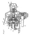
- Fig. 2 is a sectional view of an intermediate differential unit assemb-ed within the power transmission of Fig. 1;
- Fig. 3 is an enarged sectional view of the intermediate differential unit of Fig. 2;
- Fig. 4 is a sectional view of an intermediate differential unit assemb ed within another embodiment of the power transmission;
- Fig. 5 is an enlarged sectional view of the intermediate differential unit of Fig. 4; and
- Fig. 6 is an enlarged sectional view of a modification of the intermediate differential unit of Fig. 4.
- Referring now to the drawings, particularly in Fig. 1, there is schematically illustrated a four-wheel drive vehicle which is equipped with a
prime mover 14 at an intermediate portion thereof. A power transmission of the present invention includes atransmission casing 11 secured to the cylinder block ofprime mover 14 to contain therein aclutch 12, adifferential unit 13 for rear-wheel drive, a chance-speed gearing 20, an intermediatedifferential unit 30a, and ashift mechanism 30b. As is illustrated in Fig. 2, the change-speed gearing 20 is in the forn of a manual transmission which comprises aninput shaft 21 coaxially connoted to an output shaft of theprime mover 14 through theclutch 12, an outputhollow shaft 22 arranged in parallel with theInput shaft 21, and change-speed gears 23 respectively mounted on the input andoutput shafts hollow shaft 22 is drivingly connected to adrive shaft 15 for front-wheel drive by way of the intermediatedifferential unit 30a and is further drivingly connected to adrive pinion shaft 17 for rear-wheel drive by way of the intermediatedifferential unit 30a. - As shown in Fig. 1, the
drive shaft 15 is arranged in parallel wi:h the input andoutput shafts front axles inversion mechanism 16a, apropeller shaft 16b and adifferential unit 16c for front-wheel drive. Thedrive pinion shaft 17 is disposed within the outputhollov shaft 22 and is drivingly connected to a pair ofrear axles input shaft 21 is applied with a driving torque from theprime mover 14 through theclutch 12 to drive theoutput shaft 22 through an established drive power train of the change-speed gears 23. The driving torque ofoutput shaft 22 is distributed by the intermediatedifferential unit 30a to drive thedrive shaft 15 and thedrive pinion shaft 17. - As is illustrated in Fig. 3, the intermediate
differential unit 30a conprises adifferential casing 31, a pair ofpinion gears side gear 34 for rear-wheel drive. The d.fferential casing 31 has one end fixed to the outer end ofoutput shaft 22 and the other end rotatably supported from thetransmission casing 11. Thepinion gears 32 each are contained within thecasing 31 and rotatably mounted on apinion shaft 35 carried on thecasing 31. Thepinion gears 32 each are integrally formed with three stepped toothed portions 32a, 32b and 32c which are arranged i1 an axial direction of thepinion shaft 35. The sile gears 33a, 33b and 33c for front-wheel drive are formed in different diameter and mounted concentrically within thecasing 31 for relative rotation. The side gears 33a, 33b, 33c are in meshing engagement with the respective toothed portions 32a, 32b, 32c ofpinion gears 32. Theside gear 34 for rear-wheel drive is rotatably mounted within thecasing 31 and fixedly mounted on the oster end ofdrive pinion shaft 17. Theside gear 34 is in meshing engagement with the outermost toothed portion 32a ofpinion gear 32. Arranged between thecasing 31 and theside gear 34 is africtional restriction mechanism 36 which is adapted to restrict excessive relative rotation between thecasing 31 and theside gear 34. - The
shift mechanism 30b includes aslide shaft 37 arranged to be shifted by alever 38. Theslide shaft 37 is slidably disposed within sleeve portions of the side gears 33a, 33b, 33c through asleeve portion 39a of anoutput gear 39. Theslide shaft 37 is formed thereon with axially spacedouter splines 37a and 37b, theformer spline 37a being permanently engaged with aninner spline 39b of thesleeve portion 39a ofoutput gear 39, and the latter spline 37b being arranged to be selectively engaged with respective inner splines 33a1, 33b,, 33cl of the side gears 33a, 33b, 33c. Theoutput gear 39 is rotatably supported from thetransmission casing 11 and is permanently in meshing engagement with an input gear l5a which is rotatably supported from thetransmission casing 11 and fixed to thedrive shaft 15. Thelever 38 is slidably mounted on anaxial support shaft 38a fixed to thetransmission casing 11 and operatively connected through an appropriate linkage (not shown) to a manual shift lever which is arranged in the vehicle compartment to be operated by an operator. - In operation of the intermediate
differential unit 30a, thecasing 31 is rotated by the driving torque applied thereto from theoutput shaft 22 of change-speed gearing 20 to drive thepinion gears pinion gears tha slide shaft 37 and thedrive pinion shaft 17. Theslide shaft 37 acts to rotate thedrive shaft 15 through the output andinput gears front axles drive pinion shaft 17 acts to transmit the driving torque to therear axles differential unit 13 for rear-wheel drive. Assuming that in such operation, theslide shaft 37 has been shifted to a backward position to engage the inner spline 33a1 of the first side gear 33a at its outer spline 37b, the first side gear 33a acts to transmit the driving torque to thedrive shaft 15 through theslide shaft 37. As the diameter of the first side gear 33a is substantially the same as that of theside gear 34, the driving torque is distributed to the front and rear axles at a gear ratio of 1 : 1. When theslide shaft 37 is shifted to an intermediate position to engage the inner spline 33bI of the second side gear 33b at its outer spline 37b, the second side gear 33b acts to transmit the driving torque to thedrive shaft 15 through theslide shaft 37. As the diameter of the second side gear 33b is smallar than that of theside gear 34, the driving torque is distributed to the frcnt and rear axles at a gear ratio between theside gears 33b and 34. When theslide shaft 37 is shifted to a forward position to engage the inner spline 33cI of the third side gear 33c at its outer spline 37b, the third side gear 33c acts to transmit the driving torque to thedrjve shaft 15 through theslide shaft 37. As the diameter of the third side gear 33c is further smaller than that of theside gear 34, the driving torque is distributed to the front and rear axles at a gear ratio betweentie side gears 33c and 34. - From the above description, it will be understood that the intermediate
differential unit 30a acts to change the distribution ratio of the driving torque at three steps in accordance with a road condition so as to ensure stable maneuverability of the vehicle. Furthermore, it will be understood that with the above arrangement of the intermediatedifferential unit 30a andshift mechanism 30b, the power transmission can be constructed in a relatively small size to be installed in a limited space of the vehicle. - In Figs. 4 and 5. there is illustrated another embodiment of the power transmission, wherein an intermediate
differential unit 40a and ashift mechanism 40b are arranged in parallel with theoutput shaft 22 of change-speed gearing 20, and wherein acasing 41 of the intermediatedifferential unit 40a is drivingly connected to theoutput shaft 22 of change-speed gearing 20 by means of a pair of intermeshedgears gear 24 is fixed to theottput shaft 22 of change-speed gearing 20, and the gear 4la is integrally formed on thedifferential casing 41. In the intermediatedifferential unit 40a, a pair ofpinion gears pinion shafts casing 31. Thepinion gears pinion gears 42 are permanently in meshing engagement with a smalldiameter side gear 43 for front-wheel drive which is fixed to thedrive shaft 15. The side gears 44a and 41b for rear-wheel drive are formed in different diameter and are concentrically mounted within thecasing 41 for relative rotation. In the above arrangement, the diameter of the first side gear 44a is larger than that of the second side gear 44b, and the diameter ofside gear 43 for front-wheel drive is substantially the same as that of the second side gear 44b. Arranged between thecasing 41 and theside gear 43 is ahydraulic restriction mechanism 46 which is adapted to restrict excessive relative rotation between thecasing 41 and theside gear 43. - The
shift mechanism 40b includes aslide shaft 47 arranged to be shifte3 by alever 48. Theslide shaft 47 is axially slidably disposed within sleeve portions of the side gears 44a, 44b through anoutput gear 49. Theslide shaft 47 is formed thereon with axially spacedouter splines former spline 47a being permanently engaged with an inner spline of theoutput gear 49, and thelatter spline 47b being arranged to be selectively engaged with respective inner splines of the side gears 44a and 44b. Theoutput gear 49 is rotatably supported from thetransnission casing 11 and is permanently in meshing engagement with aninput gear 17a fixed to thedrive pinion shaft 17. Thelever 48 is slidably mounted on anaxial support shaft 48a fixed to thetransmission casing 11 and operatively connected through an appropriate linkage (not shown) to a manual shift lever which is arranged in the vehicle compartment to be operated by an operator. - In operation of the intermediate
differential unit 40a, thecasing 41 is rotated by the driving torque applied thereto from theoutput shaft 22 of change-speed gearing 20 through the intermeshed gears 24, 41a to drive the pinion gears 42, 42, and in turn, the side gears 43, 44a and 44b are rotated by the pinion gears 42, 42 to drive thedrive shaft 15 and theslide shaft 47. Thedrive shaft 15 acts to transmit the driving torque to thefront axles inversion mechanism 16a,propeller shaft 16b anddifferential unit 16c, while theslide shaft 47 acts to rotate thedrive pinion shaft 17 through the output and input gears 49 and 17a for transmitting the driving torque to therear axles differential unit 13. Assuming that in such operation, theslide shaft 47 has been shifted to a backward position to engage the inner spline of the first side gear 44a at itsouter spline 47b, the first side gear 44a acts to transmit the driving torque to thedrive pinion shaft 17 through theslide shaft 47. Thus, the driving torque is distrituted to the front and rear axles at a gear ratio between the side gears 43 and 44a. - When the
slide shaft 47 is shifted to a forward position to engage the inner spline of the second side gear 44b at itsouter spline 47b, the second side gear 44b acts to transmit the driving torque to thedrive pinion shaft 17 through theslide shaft 47. Thus, the driving torque is distributed to the front and rear axles at a gear ratio of 1 : 1 because the diameter of side gear 44b is substantially the same as that of theside gear 43 for front-wheel drive. From the above description, it will be understood that the intermediatedifferential unit 40a acts to change the distribution ratio of the driving torque at two steps in accordance with a road condition so as to ensure stable maneuverability of the vehicle. In this embodiment, it is advantageous that the power transmission can be constructed in a relatively short length owing to the parallel arrangement of the intermediatedifferential unit 40a in relation to the change-speed gearing 20. - In Fig. 6, a modification of the intermediate
differential unit 40a is designated by thereference numeral 50a, wherein thepinion shafts af unit 40a are replaced with a pair ofinclined pinion shafts differential casing 51 at an angle, and wherein the side gears 44a, 44b ofunit 40a are replaced withside gears differential casing 51. In this modification, both the side gears 54a, 54b are formed larger ih diameter than aside gear 53 for front-wheel drive. The other construction of thedifferential unit 50a is substantially the same as that of thedifferential unit 40a shown in Figs. 4 and 5. In operation of thedifferential unit 50a, the driving torque applied from theoutput shaft 22 of change-speed gearing 20 is distributed to the front and rear axles at a gear ratio between the side gears 53 and 54a or 54b. When theslide shaft 47 is shifted to engage the inner splines of side gears 54a and 54b at itsouter splines differential unit 50a is locked by interconnection of the side gears 54a and 54b without provision of any locking mechanism.
Claims (10)
Applications Claiming Priority (4)
| Application Number | Priority Date | Filing Date | Title |
|---|---|---|---|
| JP20244284A JPS6181226A (en) | 1984-09-27 | 1984-09-27 | Power transmitting device for four wheel drive car |
| JP202442/84 | 1984-09-27 | ||
| JP201815/84 | 1984-12-24 | ||
| JP20181584U JPS61109830U (en) | 1984-12-24 | 1984-12-24 |
Publications (3)
| Publication Number | Publication Date |
|---|---|
| EP0177286A2 true EP0177286A2 (en) | 1986-04-09 |
| EP0177286A3 EP0177286A3 (en) | 1987-01-14 |
| EP0177286B1 EP0177286B1 (en) | 1989-01-11 |
Family
ID=26513010
Family Applications (1)
| Application Number | Title | Priority Date | Filing Date |
|---|---|---|---|
| EP85306877A Expired EP0177286B1 (en) | 1984-09-27 | 1985-09-27 | Power transmission for four-wheel drive vehicle |
Country Status (3)
| Country | Link |
|---|---|
| US (1) | US4671136A (en) |
| EP (1) | EP0177286B1 (en) |
| DE (1) | DE3567414D1 (en) |
Cited By (12)
| Publication number | Priority date | Publication date | Assignee | Title |
|---|---|---|---|---|
| EP0213959A3 (en) * | 1985-09-03 | 1987-08-26 | Toyota Jidosha Kabushiki Kaisha | Four wheel drive power transmission system with front propeller shaft including no universal joints connecting transfer device to front differential |
| US4721011A (en) * | 1985-09-04 | 1988-01-26 | Toyota Jidosha Kabushiki Kaisha | Four wheel drive power transmission system with front propeller shaft including no universal joints connecting transfer device to front differential |
| US4779699A (en) * | 1986-04-30 | 1988-10-25 | Mazda Motor Corporation | Four wheel drive vehicle with inter-axle differential having dual planetary gear sets |
| GB2216077A (en) * | 1988-01-18 | 1989-10-04 | Honda Motor Co Ltd | Front and rear road wheel drive apparatus for motor vehicle |
| US4875978A (en) * | 1986-08-20 | 1989-10-24 | Mazda Motor Corporation | Vehicle four wheel drive system |
| DE4107286A1 (en) * | 1990-03-09 | 1991-09-12 | Mazda Motor | CONSTRUCTION OF A DRIVELINE OF A MOTOR VEHICLE |
| GB2250246A (en) * | 1990-11-28 | 1992-06-03 | Rover Group | Wheeled motor vehicle with contra-rotating drive shafts, eg four-wheel-drive vehicle |
| EP0820892A3 (en) * | 1996-07-26 | 1998-12-02 | New Venture Gear, Inc. | Transmission for four-wheel drive vehicles |
| US6030312A (en) * | 1996-06-06 | 2000-02-29 | Rover Group Limited | Motor vehicle power train |
| DE10253416A1 (en) * | 2002-11-08 | 2004-05-27 | Getrag Getriebe- Und Zahnradfabrik Hermann Hagenmeyer Gmbh & Cie Kg | Step ratio all indirect gearbox for road vehicle has hollow layshaft containing shaft taking drive from first differential to differential for front axle |
| WO2015021963A1 (en) * | 2013-08-12 | 2015-02-19 | Schaeffler Technologies Gmbh & Co. Kg | Differential assembly |
| WO2015132066A1 (en) * | 2014-03-06 | 2015-09-11 | Aktiebolaget Skf | Change-speed gearbox |
Families Citing this family (15)
| Publication number | Priority date | Publication date | Assignee | Title |
|---|---|---|---|---|
| DE3545540A1 (en) * | 1985-12-21 | 1987-07-02 | Audi Ag | Drive device for a four-wheel drive motor vehicle |
| MX160231A (en) * | 1986-02-27 | 1990-01-10 | Clenet Alain J M | IMPROVEMENTS IN A DRIVE TRAIN FOR A VEHICLE |
| US4805720A (en) * | 1986-02-27 | 1989-02-21 | Clenet Alain J M | Vehicle drivetrain |
| JPS62218228A (en) * | 1986-03-19 | 1987-09-25 | Toyota Motor Corp | Controlling method for four-wheel drive running gear |
| DE3762207D1 (en) * | 1986-05-23 | 1990-05-17 | Toyota Motor Co Ltd | POWER DISTRIBUTION DEVICE FOR FOUR-WHEEL DRIVE. |
| DE3786560T2 (en) * | 1987-06-04 | 1994-01-20 | Gleason Works | CONTINUOUSLY VARIABLE DIFFERENTIAL GEARBOX. |
| US5662543A (en) * | 1995-11-13 | 1997-09-02 | New Venture Gear, Inc. | Transmission for four-wheel drive vehicles |
| JPH10194001A (en) * | 1997-01-16 | 1998-07-28 | Tochigi Fuji Ind Co Ltd | Differential device |
| US6142905A (en) | 1997-03-21 | 2000-11-07 | New Venture Gear, Inc. | Full-time four-wheel drive transmission with limited slip clutch |
| US5904632A (en) * | 1997-03-21 | 1999-05-18 | New Venture Gear, Inc. | Full-time four-wheel drive transmission |
| US5989146A (en) * | 1997-03-21 | 1999-11-23 | New Venture Gear, Inc. | On-demand four-wheel drive transmission |
| SE512981C2 (en) * | 1998-10-22 | 2000-06-12 | Volvo Ab | vehicle differential |
| DE102006058835A1 (en) * | 2006-12-13 | 2008-06-19 | Magna Powertrain Ag & Co Kg | differential gear |
| ITPR20120029A1 (en) * | 2012-05-11 | 2013-11-12 | Primo Zanella | NEW SPEED REDUCER |
| RU174714U1 (en) * | 2016-12-23 | 2017-10-30 | Публичное акционерное общество "КАМАЗ" | AUTOMATIC TRANSMISSION BOX SWITCHING SYSTEM |
Family Cites Families (15)
| Publication number | Priority date | Publication date | Assignee | Title |
|---|---|---|---|---|
| FR48974E (en) * | 1938-10-05 | |||
| DE138677C (en) * | 1901-08-13 | 1903-02-21 | ||
| US860952A (en) * | 1904-04-30 | 1907-07-23 | White Eng Co | Compensating gearing for motor-vehicles. |
| US1247494A (en) * | 1917-03-21 | 1917-11-20 | V Berquist | Differential transmission. |
| US1812801A (en) * | 1929-03-25 | 1931-06-30 | Glen F Nus | Front wheel drive for automobiles |
| US2073029A (en) * | 1934-03-15 | 1937-03-09 | Daimler Benz Ag | Motor vehicle |
| GB453838A (en) * | 1934-03-15 | 1936-09-15 | Daimler Benz Ag | Improvements in and relating to motor vehicles |
| FR836807A (en) * | 1937-04-13 | 1939-01-26 | Deutsche Werke Kiel Ag | Power transmission device applicable, in particular, to motor vehicles and comprising a normal gear change mechanism and a planetary gear mechanism |
| US2395108A (en) * | 1942-07-17 | 1946-02-19 | Four Wheel Drive Auto Co | Drive for multiple axle vehicles |
| US2686437A (en) * | 1952-02-05 | 1954-08-17 | Victor E Murray | Two-speed direct drive rear axle |
| GB1126805A (en) * | 1964-10-20 | 1968-09-11 | Ferguson Res Ltd Harry | Improvements in or relating to centre differential gear units |
| GB1132354A (en) * | 1965-03-31 | 1968-10-30 | Auto Transmissions Ltd | Power transmission system |
| FR1431408A (en) * | 1965-04-09 | 1966-03-11 | Tatra Np | Transmission for motor cars with two powered axles |
| GB1138943A (en) * | 1965-12-29 | 1969-01-01 | Ferguson Res Ltd Harry | Improvements in or relating to four-wheel-drive motor vehicles |
| US4305313A (en) * | 1979-12-06 | 1981-12-15 | Eaton Corporation | Differential case fastener |
-
1985
- 1985-09-26 US US06/780,316 patent/US4671136A/en not_active Expired - Fee Related
- 1985-09-27 EP EP85306877A patent/EP0177286B1/en not_active Expired
- 1985-09-27 DE DE8585306877T patent/DE3567414D1/en not_active Expired
Cited By (16)
| Publication number | Priority date | Publication date | Assignee | Title |
|---|---|---|---|---|
| EP0213959A3 (en) * | 1985-09-03 | 1987-08-26 | Toyota Jidosha Kabushiki Kaisha | Four wheel drive power transmission system with front propeller shaft including no universal joints connecting transfer device to front differential |
| US4721011A (en) * | 1985-09-04 | 1988-01-26 | Toyota Jidosha Kabushiki Kaisha | Four wheel drive power transmission system with front propeller shaft including no universal joints connecting transfer device to front differential |
| US4779699A (en) * | 1986-04-30 | 1988-10-25 | Mazda Motor Corporation | Four wheel drive vehicle with inter-axle differential having dual planetary gear sets |
| US4875978A (en) * | 1986-08-20 | 1989-10-24 | Mazda Motor Corporation | Vehicle four wheel drive system |
| GB2216077B (en) * | 1988-01-18 | 1992-07-15 | Honda Motor Co Ltd | Front and rear road wheel drive apparatus for motor vehicle |
| US4981191A (en) * | 1988-01-18 | 1991-01-01 | Honda Giken Kogyo Kabushiki Kaisha | Front and rear road wheel drive apparatus for motor vehicle |
| GB2216077A (en) * | 1988-01-18 | 1989-10-04 | Honda Motor Co Ltd | Front and rear road wheel drive apparatus for motor vehicle |
| DE4107286A1 (en) * | 1990-03-09 | 1991-09-12 | Mazda Motor | CONSTRUCTION OF A DRIVELINE OF A MOTOR VEHICLE |
| GB2250246A (en) * | 1990-11-28 | 1992-06-03 | Rover Group | Wheeled motor vehicle with contra-rotating drive shafts, eg four-wheel-drive vehicle |
| GB2250246B (en) * | 1990-11-28 | 1994-07-13 | Rover Group | A wheeled motor vehicle |
| US6030312A (en) * | 1996-06-06 | 2000-02-29 | Rover Group Limited | Motor vehicle power train |
| EP0820892A3 (en) * | 1996-07-26 | 1998-12-02 | New Venture Gear, Inc. | Transmission for four-wheel drive vehicles |
| DE10253416A1 (en) * | 2002-11-08 | 2004-05-27 | Getrag Getriebe- Und Zahnradfabrik Hermann Hagenmeyer Gmbh & Cie Kg | Step ratio all indirect gearbox for road vehicle has hollow layshaft containing shaft taking drive from first differential to differential for front axle |
| DE10253416B4 (en) * | 2002-11-08 | 2009-04-30 | Getrag Getriebe- Und Zahnradfabrik Hermann Hagenmeyer Gmbh & Cie Kg | Multi-step transmission for a motor vehicle |
| WO2015021963A1 (en) * | 2013-08-12 | 2015-02-19 | Schaeffler Technologies Gmbh & Co. Kg | Differential assembly |
| WO2015132066A1 (en) * | 2014-03-06 | 2015-09-11 | Aktiebolaget Skf | Change-speed gearbox |
Also Published As
| Publication number | Publication date |
|---|---|
| DE3567414D1 (en) | 1989-02-16 |
| EP0177286A3 (en) | 1987-01-14 |
| US4671136A (en) | 1987-06-09 |
| EP0177286B1 (en) | 1989-01-11 |
Similar Documents
| Publication | Publication Date | Title |
|---|---|---|
| EP0177286A2 (en) | Power transmission for four-wheel drive vehicle | |
| EP0180374B1 (en) | Power transmission for four-wheel drive vehicle | |
| US4428452A (en) | Four-wheel-drive system for vehicle | |
| US4304141A (en) | Tractor power take-off system | |
| EP0192324A2 (en) | Power transfer device for four-wheel drive vehicle | |
| EP0131892A1 (en) | Power transfer device for four wheel drive | |
| US5640882A (en) | Indirect manual transmission for motor vehicles having cross-country | |
| EP0226666B1 (en) | Four-wheel vehicle drive system | |
| US4459874A (en) | Transaxle mechanism of four-wheel vehicle drive system | |
| US4875978A (en) | Vehicle four wheel drive system | |
| EP1120587B1 (en) | Automobile transmission | |
| JPH0211448B2 (en) | ||
| US4819506A (en) | Power transmitting system for a four-wheel drive vehicle | |
| EP0024454B1 (en) | Power transmission unit for motor vehicles | |
| GB2110323A (en) | Motor vehicle transmission | |
| EP0246926A2 (en) | Power transfer device for four-wheel drive | |
| US4967616A (en) | Shift mechanism in power transfer device | |
| EP0304275A2 (en) | Manual transmission for motor vehicle | |
| EP0242338B1 (en) | Motor vehicle transmission system | |
| US4876919A (en) | Power transfer device for four-wheel drive | |
| EP0274169B1 (en) | Power transmission device for a four wheel drive vehicle | |
| US6254506B1 (en) | Transmission for four-wheel drive vehicle | |
| EP0304334A2 (en) | Manual transmission for motor vehicle | |
| JPS6181226A (en) | Power transmitting device for four wheel drive car | |
| EP0305136A2 (en) | Manual transmission for motor vehicle |
Legal Events
| Date | Code | Title | Description |
|---|---|---|---|
| PUAI | Public reference made under article 153(3) epc to a published international application that has entered the european phase |
Free format text: ORIGINAL CODE: 0009012 |
|
| AK | Designated contracting states |
Kind code of ref document: A2 Designated state(s): DE FR GB |
|
| PUAL | Search report despatched |
Free format text: ORIGINAL CODE: 0009013 |
|
| AK | Designated contracting states |
Kind code of ref document: A3 Designated state(s): DE FR GB |
|
| 17P | Request for examination filed |
Effective date: 19870126 |
|
| 17Q | First examination report despatched |
Effective date: 19871202 |
|
| GRAA | (expected) grant |
Free format text: ORIGINAL CODE: 0009210 |
|
| AK | Designated contracting states |
Kind code of ref document: B1 Designated state(s): DE FR GB |
|
| REF | Corresponds to: |
Ref document number: 3567414 Country of ref document: DE Date of ref document: 19890216 |
|
| ET | Fr: translation filed | ||
| PLBE | No opposition filed within time limit |
Free format text: ORIGINAL CODE: 0009261 |
|
| STAA | Information on the status of an ep patent application or granted ep patent |
Free format text: STATUS: NO OPPOSITION FILED WITHIN TIME LIMIT |
|
| 26N | No opposition filed | ||
| PGFP | Annual fee paid to national office [announced via postgrant information from national office to epo] |
Ref country code: FR Payment date: 19920909 Year of fee payment: 8 |
|
| PGFP | Annual fee paid to national office [announced via postgrant information from national office to epo] |
Ref country code: GB Payment date: 19920917 Year of fee payment: 8 |
|
| PGFP | Annual fee paid to national office [announced via postgrant information from national office to epo] |
Ref country code: DE Payment date: 19921005 Year of fee payment: 8 |
|
| PG25 | Lapsed in a contracting state [announced via postgrant information from national office to epo] |
Ref country code: GB Effective date: 19930927 |
|
| GBPC | Gb: european patent ceased through non-payment of renewal fee |
Effective date: 19930927 |
|
| PG25 | Lapsed in a contracting state [announced via postgrant information from national office to epo] |
Ref country code: FR Free format text: LAPSE BECAUSE OF NON-PAYMENT OF DUE FEES Effective date: 19940531 |
|
| PG25 | Lapsed in a contracting state [announced via postgrant information from national office to epo] |
Ref country code: DE Effective date: 19940601 |
|
| REG | Reference to a national code |
Ref country code: FR Ref legal event code: ST |