EP0177213B1 - Telescopic tool adapter - Google Patents
Telescopic tool adapter Download PDFInfo
- Publication number
- EP0177213B1 EP0177213B1 EP19850306592 EP85306592A EP0177213B1 EP 0177213 B1 EP0177213 B1 EP 0177213B1 EP 19850306592 EP19850306592 EP 19850306592 EP 85306592 A EP85306592 A EP 85306592A EP 0177213 B1 EP0177213 B1 EP 0177213B1
- Authority
- EP
- European Patent Office
- Prior art keywords
- tool
- tool holder
- spindle
- transducer
- adapter
- Prior art date
- Legal status (The legal status is an assumption and is not a legal conclusion. Google has not performed a legal analysis and makes no representation as to the accuracy of the status listed.)
- Expired - Lifetime
Links
Images


Classifications
-
- G—PHYSICS
- G05—CONTROLLING; REGULATING
- G05B—CONTROL OR REGULATING SYSTEMS IN GENERAL; FUNCTIONAL ELEMENTS OF SUCH SYSTEMS; MONITORING OR TESTING ARRANGEMENTS FOR SUCH SYSTEMS OR ELEMENTS
- G05B19/00—Programme-control systems
- G05B19/02—Programme-control systems electric
- G05B19/18—Numerical control [NC], i.e. automatically operating machines, in particular machine tools, e.g. in a manufacturing environment, so as to execute positioning, movement or co-ordinated operations by means of programme data in numerical form
- G05B19/406—Numerical control [NC], i.e. automatically operating machines, in particular machine tools, e.g. in a manufacturing environment, so as to execute positioning, movement or co-ordinated operations by means of programme data in numerical form characterised by monitoring or safety
- G05B19/4065—Monitoring tool breakage, life or condition
-
- B—PERFORMING OPERATIONS; TRANSPORTING
- B23—MACHINE TOOLS; METAL-WORKING NOT OTHERWISE PROVIDED FOR
- B23Q—DETAILS, COMPONENTS, OR ACCESSORIES FOR MACHINE TOOLS, e.g. ARRANGEMENTS FOR COPYING OR CONTROLLING; MACHINE TOOLS IN GENERAL CHARACTERISED BY THE CONSTRUCTION OF PARTICULAR DETAILS OR COMPONENTS; COMBINATIONS OR ASSOCIATIONS OF METAL-WORKING MACHINES, NOT DIRECTED TO A PARTICULAR RESULT
- B23Q17/00—Arrangements for observing, indicating or measuring on machine tools
- B23Q17/09—Arrangements for observing, indicating or measuring on machine tools for indicating or measuring cutting pressure or for determining cutting-tool condition, e.g. cutting ability, load on tool
- B23Q17/0952—Arrangements for observing, indicating or measuring on machine tools for indicating or measuring cutting pressure or for determining cutting-tool condition, e.g. cutting ability, load on tool during machining
- B23Q17/0957—Detection of tool breakage
-
- B—PERFORMING OPERATIONS; TRANSPORTING
- B23—MACHINE TOOLS; METAL-WORKING NOT OTHERWISE PROVIDED FOR
- B23Q—DETAILS, COMPONENTS, OR ACCESSORIES FOR MACHINE TOOLS, e.g. ARRANGEMENTS FOR COPYING OR CONTROLLING; MACHINE TOOLS IN GENERAL CHARACTERISED BY THE CONSTRUCTION OF PARTICULAR DETAILS OR COMPONENTS; COMBINATIONS OR ASSOCIATIONS OF METAL-WORKING MACHINES, NOT DIRECTED TO A PARTICULAR RESULT
- B23Q2220/00—Machine tool components
- B23Q2220/008—Rotatable tool holders coupled in parallel to a non rotating accessory
-
- G—PHYSICS
- G05—CONTROLLING; REGULATING
- G05B—CONTROL OR REGULATING SYSTEMS IN GENERAL; FUNCTIONAL ELEMENTS OF SUCH SYSTEMS; MONITORING OR TESTING ARRANGEMENTS FOR SUCH SYSTEMS OR ELEMENTS
- G05B2219/00—Program-control systems
- G05B2219/30—Nc systems
- G05B2219/37—Measurements
- G05B2219/37245—Breakage tool, failure
-
- G—PHYSICS
- G05—CONTROLLING; REGULATING
- G05B—CONTROL OR REGULATING SYSTEMS IN GENERAL; FUNCTIONAL ELEMENTS OF SUCH SYSTEMS; MONITORING OR TESTING ARRANGEMENTS FOR SUCH SYSTEMS OR ELEMENTS
- G05B2219/00—Program-control systems
- G05B2219/30—Nc systems
- G05B2219/37—Measurements
- G05B2219/37405—Contact detection between workpiece and tool, probe, feeler
-
- G—PHYSICS
- G05—CONTROLLING; REGULATING
- G05B—CONTROL OR REGULATING SYSTEMS IN GENERAL; FUNCTIONAL ELEMENTS OF SUCH SYSTEMS; MONITORING OR TESTING ARRANGEMENTS FOR SUCH SYSTEMS OR ELEMENTS
- G05B2219/00—Program-control systems
- G05B2219/30—Nc systems
- G05B2219/49—Nc machine tool, till multiple
- G05B2219/49182—Tapping, overshoot after reversal, elasticity compensation
-
- G—PHYSICS
- G05—CONTROLLING; REGULATING
- G05B—CONTROL OR REGULATING SYSTEMS IN GENERAL; FUNCTIONAL ELEMENTS OF SUCH SYSTEMS; MONITORING OR TESTING ARRANGEMENTS FOR SUCH SYSTEMS OR ELEMENTS
- G05B2219/00—Program-control systems
- G05B2219/30—Nc systems
- G05B2219/50—Machine tool, machine tool null till machine tool work handling
- G05B2219/50136—With sensor, potentiometer to measure relative displacement
-
- Y—GENERAL TAGGING OF NEW TECHNOLOGICAL DEVELOPMENTS; GENERAL TAGGING OF CROSS-SECTIONAL TECHNOLOGIES SPANNING OVER SEVERAL SECTIONS OF THE IPC; TECHNICAL SUBJECTS COVERED BY FORMER USPC CROSS-REFERENCE ART COLLECTIONS [XRACs] AND DIGESTS
- Y10—TECHNICAL SUBJECTS COVERED BY FORMER USPC
- Y10T—TECHNICAL SUBJECTS COVERED BY FORMER US CLASSIFICATION
- Y10T408/00—Cutting by use of rotating axially moving tool
- Y10T408/13—Cutting by use of rotating axially moving tool with randomly-actuated stopping means
- Y10T408/14—Responsive to condition of Tool or tool-drive
-
- Y—GENERAL TAGGING OF NEW TECHNOLOGICAL DEVELOPMENTS; GENERAL TAGGING OF CROSS-SECTIONAL TECHNOLOGIES SPANNING OVER SEVERAL SECTIONS OF THE IPC; TECHNICAL SUBJECTS COVERED BY FORMER USPC CROSS-REFERENCE ART COLLECTIONS [XRACs] AND DIGESTS
- Y10—TECHNICAL SUBJECTS COVERED BY FORMER USPC
- Y10T—TECHNICAL SUBJECTS COVERED BY FORMER US CLASSIFICATION
- Y10T408/00—Cutting by use of rotating axially moving tool
- Y10T408/16—Cutting by use of rotating axially moving tool with control means energized in response to activator stimulated by condition sensor
- Y10T408/17—Cutting by use of rotating axially moving tool with control means energized in response to activator stimulated by condition sensor to control infeed
- Y10T408/172—Responsive to Tool
-
- Y—GENERAL TAGGING OF NEW TECHNOLOGICAL DEVELOPMENTS; GENERAL TAGGING OF CROSS-SECTIONAL TECHNOLOGIES SPANNING OVER SEVERAL SECTIONS OF THE IPC; TECHNICAL SUBJECTS COVERED BY FORMER USPC CROSS-REFERENCE ART COLLECTIONS [XRACs] AND DIGESTS
- Y10—TECHNICAL SUBJECTS COVERED BY FORMER USPC
- Y10T—TECHNICAL SUBJECTS COVERED BY FORMER US CLASSIFICATION
- Y10T409/00—Gear cutting, milling, or planing
- Y10T409/30—Milling
- Y10T409/30392—Milling with means to protect operative or machine [e.g., guard, safety device, etc.]
-
- Y—GENERAL TAGGING OF NEW TECHNOLOGICAL DEVELOPMENTS; GENERAL TAGGING OF CROSS-SECTIONAL TECHNOLOGIES SPANNING OVER SEVERAL SECTIONS OF THE IPC; TECHNICAL SUBJECTS COVERED BY FORMER USPC CROSS-REFERENCE ART COLLECTIONS [XRACs] AND DIGESTS
- Y10—TECHNICAL SUBJECTS COVERED BY FORMER USPC
- Y10T—TECHNICAL SUBJECTS COVERED BY FORMER US CLASSIFICATION
- Y10T409/00—Gear cutting, milling, or planing
- Y10T409/30—Milling
- Y10T409/306664—Milling including means to infeed rotary cutter toward work
- Y10T409/306776—Axially
- Y10T409/306832—Axially with infeed control means energized in response to activator stimulated by condition sensor
- Y10T409/306888—In response to cutter condition
-
- Y—GENERAL TAGGING OF NEW TECHNOLOGICAL DEVELOPMENTS; GENERAL TAGGING OF CROSS-SECTIONAL TECHNOLOGIES SPANNING OVER SEVERAL SECTIONS OF THE IPC; TECHNICAL SUBJECTS COVERED BY FORMER USPC CROSS-REFERENCE ART COLLECTIONS [XRACs] AND DIGESTS
- Y10—TECHNICAL SUBJECTS COVERED BY FORMER USPC
- Y10T—TECHNICAL SUBJECTS COVERED BY FORMER US CLASSIFICATION
- Y10T409/00—Gear cutting, milling, or planing
- Y10T409/30—Milling
- Y10T409/306664—Milling including means to infeed rotary cutter toward work
- Y10T409/307224—Milling including means to infeed rotary cutter toward work with infeed control means energized in response to activator stimulated by condition sensor
- Y10T409/30728—In response to cutter condition
-
- Y—GENERAL TAGGING OF NEW TECHNOLOGICAL DEVELOPMENTS; GENERAL TAGGING OF CROSS-SECTIONAL TECHNOLOGIES SPANNING OVER SEVERAL SECTIONS OF THE IPC; TECHNICAL SUBJECTS COVERED BY FORMER USPC CROSS-REFERENCE ART COLLECTIONS [XRACs] AND DIGESTS
- Y10—TECHNICAL SUBJECTS COVERED BY FORMER USPC
- Y10T—TECHNICAL SUBJECTS COVERED BY FORMER US CLASSIFICATION
- Y10T409/00—Gear cutting, milling, or planing
- Y10T409/30—Milling
- Y10T409/306664—Milling including means to infeed rotary cutter toward work
- Y10T409/307392—Milling including means to infeed rotary cutter toward work with means to change rate of infeed
Landscapes
- Engineering & Computer Science (AREA)
- Human Computer Interaction (AREA)
- Manufacturing & Machinery (AREA)
- Physics & Mathematics (AREA)
- General Physics & Mathematics (AREA)
- Automation & Control Theory (AREA)
- Mechanical Engineering (AREA)
- Drilling And Boring (AREA)
Description
- My invention comprises a telescopic tool adapter of the type used in modern machining centers and is used in conjunction with automatic tool changers for loading into and unloading from the machine spindle.
- The principal object of my invention is to provide machining centers with a device to sense the surface of a workpiece with random length tools which devices work in conjunction with computer numerical controls (CNC) and are manufactured in a variety of sizes and configurations to accommodate the various types of machining centers and tools.
- Previous to my invention it was necessary to reference the tool to a position known as the "R" plane, therefore another object of my invention is to eliminate the necessity for the reference plane, thereby reducing the cycle time.
- Still another object of my invention is to eliminate in programming of the workpiece the "R" plane dimension, since the "R" plane is determined by the surface sensing feature.
- Another object of my invention is to eliminate the use of preset tools or set-up time for setting tool length offsets.
- Another object of my invention is to provide a tool adapter having an integral-mounted torque arm to work in conjunction with a machine mounted transducer or limit switch.
- Another object of my invention is to provide for broken tool detection during machining and after machining and for breakthrough sensing.
- Another object of my invention is to eliminate feed rate programming tapping operation by permitting the Z-axis to follow the tap into and out of the hole.
- Still another object of my invention is to provide a surface-sensing tool adapter that can be loaded in the machine spindle and retains orientation of the torque arm while stored.
- Another object of my invention is to verify the presence of a tool by utilizing a limit switch.
- In CNC machining centers, non-telescoping tool adapters are used in conjunction with an "R" plane setting and thereafter cycling to the "R" plane setting, and measuring the distance from tool point to the work surface and manually adjusting the tool length for each tool used. Alternatively, manually preset tools are employed. Another method is to utilize spindle and table probe cycles which are time-consuming and expensive.
- In GB-A-2 069 142 a 'tool to workpiece' sensing method for use on lathes is disclosed in which the procedure is to touch the tool tip against a datum to establish tool location in reference to the spindle centre-line. The tool is then positioned to contact the workpiece to establish the distance between the datum point and the outer diameter of the workpiece to be turned in the lathe. The method for determining tool tip contact consists of the following methods: completion of electrical circuit when tool makes contact; measurement of air gap resistance as tool is advanced to workpiece; tool slide displacement measured by either transformer or limit switch as tool contacts workpiece. In all of the above cases these methods require a 'pull back' cycle.
- A transducer signal is used to indicate contact of tool with workpiece but not to control deceleration of axis from rapid traverse to a null position against a positive stop for instant aneous start of feed cycle and work surface location.
- The present invention, on the other hand, provides for a controlled deceleration of the workslide upon tool contact with work surface; and for a telescoping tool adapter usable with an automatic tool changer, displacing a variable displacement transducer after tool contact with the work surface and controlling tool feed axis deceleration and providing a null position to machine control for work surface location and start of feed cycle.
- According to the present invention, there is provided, in combination, a machine tool adapter, for use in machining centres having computer numerical control (CNC), a spindle connected to said CNC and a machine-mounted electronic variable displacement transducer unit, which combination is as claimed in
claim 1.
There will now follow a description of the operation of a preferred embodiment of the said combination in various machining processes. - A variety of tool adapters can be used to accommodate the type of machining required. For drilling operations with a machining centre, a tool adapter arranged with a collet type tool holder is generally used. The collet assembly is mounted in the sliding tool holder.
- In the drilling operation, the spindle tool adapter is moved to the work surface at a rapid traverse rate until the drill contacts the work surface. At this point, the drill stops advancing, but the spindle axis continues to move toward the work surface. This causes the tool holder to telescope into the tool body which in turn causes the torque arm plunger to move a spring-loaded piston in the transducer unit. This motion causes a trip dog to trip a precision limit switch and a transducer actuator to move with respect to a transducer body. The limit switch signal is used as a safety interlock to stop the spindle axis motion if there is not the proper signal from the transducer circuit.
- In a drilling cycle, the spindle axis will continue to move toward the work surface, but at an ever-decreasing rate that is controlled by the ever-changing position of the transducer actuator in relation to the transducer body. This change in relationship causes the signals being output by the transducer to an axis velocity control circuit in the machine CNC (Computer Numerical Control) to decelerate the spindle axis to zero velocity within the telescoping travel of the tool adapter. When full adapter travel is reached, the tool holder is seated solidly in the adapter body, thereby being able to transmit thrust to the tool. The full adapter travel also causes the transducer to send a signal to the machine CNC control. This signal immediately causes the spindle axis to feed the drill into the workpiece at a programmed feed rate to a programmed depth measured from the signal point which is the work surface. At the programmed depth, the spindle will retract to a point that brings the tool clear of the work surface if another hole is to be drilled for the spindle will retract to a tool change position if another tool is required.
- If the drill breaks before the programmed depth is reached, the spring-loaded tool holder will unseat in the adapter body. This action will cause the torque arm to move, allowing the spring-loaded transducer piston to move the transducer actuator in relation to the transducer body. The transducer will signal an out of null condition to the CNC, thereby causing the machining cycle to be held up until the conditions are corrected.
- In advanced CNC logic, the initial surface sense position can be put in memory. This information can be used to determine if a drill was broken on a previous operation but went undetected. If the drill was broken, the surface sense position of the new cycle would be different than that with a full length drill. This difference in position will cause the machine cycle to be held up until the problem is corrected.
- If broken tool detection is not required, then this same logic and tool adapter action can be used to sense then a drill has broken through the workpiece thickness. This may be the case when using larger diameter drills for drilling through holes from irregular surfaces of large castings or weldments.
- For tapping operations, a telescoping tool adapter similar to the one used for drilling is used in conjunction with the drilling transducer unit, the difference being in the construction of the sliding tool holder. Instead of a collet holder, a conventional tap driver is used. The tap driver can be either torque-limiting or not.
- In operation, the spindle tool adapter is moved to the work surface at a rapid traverse rate until the non-rotating tap contacts the work surface. At this point, the tap stops-advancing, but the spindle axis continues to move toward the work surface. This causes the tool holder to telescope into the tool body which, in turn, causes the torque arm plunger to move a spring-loaded piston in the transducer unit. This motion causes a trip dog to trip a precision limit switch and a transducer actuator to move with respect to a transducer body. The limit switch signal is used as a safety interlock to stop the spindle axis motion in the absence of the proper signal from the transducer circuit.
- In a tapping cycle, the spindle axis will continue to move toward the work surface, but at an ever-decreasing rate that is controlled by the ever-changing position of the transducer actuator in relation to the transducer body. This change in relationship causes the signals being output by the transducer to an axis velocity control circuit in the machine CNC control to decelerate the spindle axis to zero velocity within one-half of the telescoping travel of the tool holder and one-half the travel of the transducer actuator. This amount of travel in the tapping mode causes the transducer to output a null signal to the CNC control. This signal immediately causes the spindle to rotate at the programmed speed. The tool holder spring pressure will cause the tap to feed into the workpiece. As the tap feeds into the workpiece, the transducer unit is displaced from the tapping null position. This information is fed into the CNC control, which causes the spindle feed axis to advance the spindle toward the work surface. As the tap continues into the workpiece, the spindle follows the tap because the transducer unit displacement establishes the velocity of the spindle axis to be the same as the rate of penetration of the tap.
- The control will track the position of the spindle axis and, at a depth programmed from the work surface, which was established when the transducer null signal was first triggered, the spindle will be reversed. The tap will then cause the tool to telescope into the tool adapter, which will cause the transducer unit to pass through the null position. In this case, the signal will come from the opposite side of null which will cause the spindle axis to retract or move away from the work surface. It will continue to move away until the tap clears the work part if another hole is to be tapped, or the spindle will retract to a tool change position if another tool is required.
- If, when using a non-torque limit tap driver, the tap should break before the programmed depth is reached, two possible events may take place. If the tap disintegrates and a large portion of the tap length is thrown clear, the spring-loaded tool holder will move rapidly away from the previous position and a gross out of null signal will occur. If there is no portion of the tap thrown clear, the spindle axis will continue to advance slightly until a null position is reached because a broken tap will not advance into the work.
- In either case, the transducer will signal the CNC control that an improper transducer position is present, thereby causing the machine cycle to be held up until the conditions are corrected.
- If, when using the torque-limiting tap driver the tap becomes dull, the tap driver will stall and the tap will stop advancing before the programmed depth is reached. This will cause the spindle axis to advance slightly until the null position is reached. The transducer will signal the CNC control that an improper transducer position is present, thereby causing the machine cycle to be held up until the conditions are corrected.
- If, on a previous machining operation, a hole for the tap to enter has not been drilled, the tap cannot begin to feed from the surface sense position. After an appropriate amount of time, the CNC control will recognize that an initial out of null condition did not occur, thereby causing the machine cycle to be held up until the conditions are corrected.
- In advanced CNC logic, the initial surface sense position can be put in memory. This information can be used to determine if a tap was broken on a previous operation, but went undetected. If the tap was broken, the surface sense position of the new cycle would be different than that with a full-length tap. This difference in position will cause the machine cycle to be held up until the problem is corrected.
- For milling operations, a telescoping tool adapter similar to the one used for drilling is used in conjunction with the drilling transducer unit, the difference being that the milling adapter is arranged to stay in the telescoped or compressed state during milling. The tool holder portion of the adapter is also arranged to mount the various types of milling cutters or, in some cases, single-point fly cutters.
- In operation, the spindle tool holder adapter is moved to the work surface at a rapid traverse rate until the non-rotating cutter contacts the work surface. At this point, the cutter stops advancing, but the spindle axis continues to move toward the work surface. This causes the tool holder to telescope into the tool body, which, in turn, causes the torque arm plunger to move a spring-loaded piston in the transducer unit. This motion causes a trip drog to trip a precision limit switch and a transducer actuator to move with respect to a transducer body. The limit switch signal is used as a safety interlock to stop the spindle axis motion if there is not the proper signal from the transducer circuit.
- In a normal milling cycle, the spindle axis will continue to move toward the work surface, but at an ever-decreasing rate that is controlled by the ever-changing position of the transducer actuator in relation to the transducer body. This change in relationship causes the signals being output by the transducer to an axis-velocity control circuit in the machine CNC control to decelerate the spindle axis to zero velocity within the telescoping travel of the tool adapter. When full adapter travel is reached, the tool holder is seated solidly in the adapter body, thereby being able to transmit thrust to the tool. The tool holder is locked rigidly in the seated position by a series of balls located in a series of holes in the adapter body working in conjunction with cam surfaces on the outside diameter of the tool holder and the inside diameter of the sliding sleeve. The sliding sleeve is spring-loaded in such a way that the locking angle of the internal cam surface forces the balls into the cam surface of the tool body, thereby locking the tool holder in the seated position.
- The full adapter travel also causes the transducer to output a signal to the machine CNC control. This signal immediately causes the spindle to rotate and feed the required axis to perform a milling operation measured from the surface of the workpiece.
- When the milling operation is complete, the spindle axis is returned to the tool change position. At this time, if it is desirable to use the milling adapter in the locked position, the adapter can be stored in the automatic tool change magazine. If, however, a surface sense cycle is required, the next time the adapter can be reset by energizing an air valve which directs air to the spring-loaded piston in the transducer unit. This air pressure will apply a thrust load of sufficient force to the torque arm and sliding sleeve assembly to compress the springs holding the sliding sleeve in position, thereby releasing the cam lock arrangement, which will allow the tool holder to reset to its normal surface sensing position.
- In the drawings, the same reference numerals are used throughout the several views and refer to the same parts, and the sectional views are taken looking in the direction of the arrows at the ends of the section lines.
- Referring now to the drawings, I show:
- FIG. 1
- is a side elevation of a machining center showing my invention inserted in the spindle.
- FIG. 2
- is a front elevation of a machining center showing my invention from a different view.
- FIG. 3
- is an enlarged view of the spindle area showing my invention in more detail.
- FIG. 4
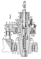
- is a section of the tool adapter portion of my invention that is arranged for drilling, taken along the lines 4-4 of FIG. 3.
- FIG. 5
- is a section taken along the lines 5-5 of FIG. 4.
- FIG. 6
- is a section taken along the lines 6-6 of FIG. 5.
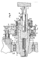
- FIG. 7
- is a section of the tool adapter portion of my invention similar to FIG. 4, partially compressed, that is arranged for tapping.
- FIG. 8
- is a section of the tool adapter portion of my invention similar to FIGS. 4 and 7 that is arranged for milling with the adapter extended.
- FIG. 9
- is a section of the tool adapter portion of my invention similar to FIG. 8 that is arranged for milling with the adapter in a latched position.
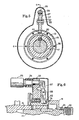
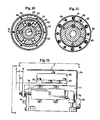
- FIG. 10
- is a section along the lines 10-10 of FIG. 9.
- FIG. 11
- is a section along the lines 11-11 of FIG. 9.
- FIG. 12
- is a side elevation of the transducer unit portion of my invention.
- FIG. 13
- is an end view taken along the lines 13-13 of FIG. 12.
- FIG. 14
- is a top view taken along the lines 14-14 of FIG. 12.
- FIG. 15
- is a side view taken along the lines 15-15 of FIG. 13.
- FIG. 16
- is a section view taken along the lines 16-16 of FIG. 13.
- FIG. 17
- is a section view taken along the lines 17-17 of FIG. 16.
- FIG. 18
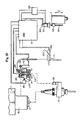
- is a mechanical, electrical and pneumatic schematic diagram of my invention.
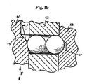
- FIG. 19
- is a section taken along the lines 19-19 of FIG. 10.
- Referring to the drawings, I show in FIGS. 1 and 2 a vertical spindle machining center having a base 9 supporting a moving
saddle 8. The saddle motion is referred to as the Y-axis. The saddle supports the workholding table 7. The table motion is referred to the X-axis. The base 9 also supports themachine column 6. Mounted tocolumn 6 isautomatic tool changer 4.Column 6 also provides a slidable mounting surface forspindle headstock 1. The vertical motion of theheadstock 1 is referred to as the Z-axis. Referring now to FIG. 3, I show aspindle housing 10 at the lower portion ofheadstock 1. Mounted tospindle housing 10 istransducer unit 3.Telescoping tool adapter 2 is retained in spindle 11 and is engaged withtransducer 3. Referring again to FIG. 2. I show aCNC control 5. - Referring to FIG. 4, I show a section through a
telescoping tool adapter 2 arranged for drilling. The adapter comprises anadapter body 15 retained in spindle 11. Slidably supported inbody 15 istool holder 17 driven by key 20 and retained byretainer 19 against pressure fromspring 18. - A
drill 24 is clamped incollet 23 bycollet lock unit 22.Tool holder 17 is axially and radially connected to slidingsleeve 31 bychip guard 41, key 29, chipguard lock unit 21 and screws 30. - The
torque arm 32 is rotatably connected to slidingsleeve 31 bybearings 35 clamped in position by innerrace bearing retainer 34 and outerrace bearing retainer 36. -
Torque arm plunger 25compresses plunger spring 26 asplunger 25 is acted upon by a heavier spring located behind transducer piston intransducer unit 3. This action will cause the shoulder ofplunger 25 to be seated against the face of thetorque arm 32 while tool adapter assembly is being inserted in spindle 11. The end of theplunger 25 is precisely located in its seated position from the gage line of the spindle taper. - The seating of plunger 25 (shown in FIG. 4 in its seated position) causes the latching
lever 27 to be pivoted aboutlever pin 33 thereby withdrawing end oflever 27 from locating notch in slidingsleeve 31. This permits free rotation of the tool adapter body during machining operations. - Latching
lever 27 is protected from chips and coolant bycover 37 fastened totorque arm 32.Plunger spring 26 is protected byspring cover 40. - When the machining operations are complete, the spindle 11 is oriented radially for the automatic tool changer to remove the adapter. This orientation lines up
notch 42 in slidingsleeve 31 with latchinglever 27. In FIG. 6, I show latchinglever 27 engaged with thisnotch 42 in slidingsleeve 31. The engagement takes place during adapter removal from spindle which causes theplunger 25 to withdraw from thetransducer unit 3. During plunger withdrawal,plunger spring 26 unseats plunger 25 causing latchinglever 27 to rotate aboutpin 33 so that end oflever 27 engages innotch 42 of slidingsleeve 31. This engagement prevents rotation, thereby retaining orientation between thetorque arm 32 and thetool body 15 while the tool adapter is being handled by the automatic tool changer and stored in the tool magazine. - During the surface-sensing operation, the spindle 11 is advanced toward the workpiece until
drill 24 contacts the work surface. The spindle or Z-axis will continue to advance, which will cause thetool holder 17 to telescope intoadapter body 15 compressingspring 18. This motion will also cause thetransducer unit 3 to advance on toplunger 25. The motion between theplunger 25 andtransducer unit 3 will cause CNC control 5 (shown in FIG. 2 and FIG. 18) to decelerate the Z-axis to zero velocity in the distance it takes the end oftool holder 17 to be seated solidly intool adapter body 15. At this point, the Z-axis will feed thedrill 24 into the work to a depth measured from the work surface by the CNC control. - If the
drill 24 should break before the depth is reached,spring 18 will causetool holder 17 to unseat intool body 15, thereby movingtorque arm 32 andplunger 25 in relation totransducer unit 3. This motion will causetransducer unit 3 to send an error signal to the CNC control which will stop the cycle until the problem is corrected. - In FIG. 5. I show a section through tool adapter assembly
showing latching lever 27 engaged innotch 42 of slidingsleeve 31. Also shown is a section throughkey 20 which transmits torque fromtool adapter body 15 totool holder 17 during machining operations. - I refer now to FIG. 7, which shows a
telescoping tool adapter 2 arranged for tapping. There are many of the same parts used in this adapter as are used in the drilling adapter shown in FIG. 4, such as thetorque arm 32,plunger 25,plunger spring 26, latchinglever 27, slidingsleeve 31,bearings 35, bearingretainers chip guard 41,lock nut 21, key 29 andscrew 30. - Specific parts for tapping are
tool holder spring 45 which determines tapping thrust pressure againsttool holder 47 which is slidably supported inadapter body 46.Tool holder 47 is driven by key 54 and retained byretainer 19. Locked intotool holder 47 bydetent balls 50, which are held in position bycollet 48, istap driver 51 of the direct drive type or the torque limiting type.Tap 52 is retained and driven bydriver 51. - The
orientation latching lever 27 works in conjunction with the slidingsleeve notch 42 in the same manner as described for the drilling adapter. - During the surface sense tapping operation, the spindle 11 is advanced toward the workpiece 53 which has been prepared for tapping by having a previously machined
hole 55 that is to be threaded bytap 52.Tap 52 is not rotating at this time. The spindle of Z-axis will continue to advance, which will cause thetool body 47 to telescope intoadapter body 46 compressingtap thrust spring 45. The amount of spring pressure can be varied by changing the compression rate ofspring 45 to suit the size oftap 52. - The telescoping motion also causes the
transducer unit 3 to advance on toplunger 25. The motion between theplunger 25 andtransducer unit 3 will causeCNC control 5 in FIG. 2 and FIG. 18 to decelerate the Z-axis to zero velocity in approximately half the travel thetool holder 47 has in theadapter body 46. - At this point, the spindle will start to rotate and the pressure determined by
spring 45 will cause the tap to feed intohole 55 to a depth measured from the work surface by the CNC control. The rate of feed is determined by the pitch oftap 52 and rotational speed of spindle 11. - As
tap 52 moves intohole 55, thetool holder 45 will start to move out ofadapter body 46. This will again cause theplunger 25 to move in relation totransducer unit 3 causing the CNC control to start feeding the spindle or Z-axis at the same rate, but slightly behindtap 52. - When the proper tap depth is reached, the spindle will reverse, which will cause the tap to back out of the hole. This action will push the
tool holder 47 further into theadapter body 46, which will cause theplunger 25 to again move in relationship totransducer unit 3. This motion will signal the CNC control to reverse the motion of the Z-axis, and the Z-axis will follow the tap out of the hole untiltap 52 is clear of the work surface. - If
tip 52 should break before the proper depth is reached, thetool holder 47 will advance very rapidly if a portion of the tap is thrown clear, or it will stop advancing because a broken tap will not continue feeding. In either case,plunger 25 will move in relation totransducer unit 3 which will signal an out of synchronization condition to the CNC control, causing the cycle to stop until the problem is corrected. - I now refer to FIG. 8, which shows a telescoping tool holder arranged for milling. There are many of the same parts used in this adapter as are used in the drill adapter shown in FIG. 4, such as the
torque arm 32,plunger 25,plunger spring 26, latchinglever 27,bearings 35, bearingretainers - Specific parts for milling are
tool holder 63, which is slidably mounted inadapter body 62, driven by key 20 and retained byretainer 19.Tool holder 63 is arranged to drivemilling cutter 65 and is connected to chipguard 69 bylock nut 21 and key 29.Chip guard 69 is slidably connected to slidingsleeve 60 byshoulder screws 66 and axially preloaded bysprings 61. Toolholder locking balls 67 work in conjunction with acam groove 72 on the outside diameter oftool holder 63 and acam groove 73 on the inside diameter of the slidingsleeve 60. - The
orientation latching lever 27 works in conjunction with slidingsleeve notch 42 in the same manner as described for the drilling adapter. - In FIG. 9, I show the same milling adapter as shown in FIG. 8 after it has been advanced by Z-axis until the
cutter 65 contactingwork surface 71 telescopes thetool holder 63 intoadapter body 62 until end tool ofholder 63 is seated solidly against bottom of bore and lockingballs 67 working in a series of holes inadapter body 62 have been cammed into locking position into the outsidediameter cam groove 72 oftool holder 65 by pressure from cam locking springs 61 against slidingsleeve 60 whose insidediameter cam groove 7 forms a locking angle, so negative cutting forces from some types of milling operations cannot unseattool holder 63. - The pressure from cam lock springs 61 and the seating effect this pressure causes against
tool holder 63 by the cam actuatedlock balls 67 is balanced against the pressure ofspring 68 so as to prevent a rapid motion oftool holder 63 during the last increment of travel oftool holder 63 being seated inadapter body 62. - In FIG. 10, I show a section through the series of holes in
adapter body 62 in which the lockingballs 67 operate in conjunction withexternal cam groove 72 oftool holder 63 andexternal cam surface 73 of slidingsleeve 60 to form a very rigid means of maintaining thetool holder 63 in a positive position inadapter body 62. - FIG. 11 is a section through a series of cam locking springs 61 which form a balanced force between
chip guard 69 and sliding sleeve 60 (not shown). - Referring now to FIG. 19, I show an enlarged section showing the locking
balls 67 being acted upon by pressure caused by cam springs 61 shown in FIG. 9, creating force F against slidingsleeve 60 and cam locking angle 0 of internalcam locking groove 73. The cam locking angle 0 is steep enough to prevent any negative cutting forces appliedaginst tool holder 63 from moving it from its seated position as shown in FIG. 9. - During a surface-sense milling operation, non-rotating spindle 11 is advanced toward the
workpiece 71 until themilling cutter 65 contacts the work surface. The spindle or Z-axis will continue to advance, causing thetool holder 63 to telescope intoadapter body 62 compressingspring 68. During this motion, thechip guard 69 being connected axially totool holder 63moves sliding sleeve 60 alongtool body 62 byspring pressure 61. Slidingsleeve 60 will continue to move in phase withtool 63 untilinternal cam groove 73 of slidingsleeve 60contacts locking balls 67. At this point, theoutside diameter groove 72 intool holder 63 has not quite lined up with lockingballs 67. Therefore, slidingsleeve 60 is momentarily stalled in its motion, which causes lockingspring 61 to compress as the Z-axis continues to feed. As thetool holder 63 approaches the seated position, its outsidediameter cam groove 72 lines up with lockingballs 67, permitting spring-loaded slidingsleeve 60 to advance, thus bringing the locking angle ofinternal cam groove 73 in line with lockingballs 67 and rigidly locking andseating tool holder 63 inadapter body 62. - The telescoping motion of the
tool holder 63 also causes motion betweenplunger 25 andtransducer unit 3 which, in turn, will cause CNC control 5 (shown in FIG. 2 and FIG. 18) to decelerate Z-axis to zero velocity in the distance it takes the end oftool holder 63 to be seated solidly inadapter body 62. At this point, control will be signalled to rotate the spindle 11 and feed the required axis to perform a milling operation measured from the surface ofwork piece 71. - After the milling operation is complete, the
tool holder 63 can be unlocked from the telescoped position by air pressure being directed to the sliding piston in thetransducer unit 3 described later. This air pressure is sufficient to overcome the pressure caused by lockingsprings 61, thereby moving slidingsleeve 60 alongadapter body 62 until internallocking cam surface 73 of slidingsleeve 60 moves away from lockingballs 67, permitting them to back out ofoutside diameter groove 72 intool holder 63 This action permitsspring 68 to return thetool holder 63 to the extended position, ready for the next surface sensing operation. - Referring now to FIG. 12, I show a side elevation of
transducer unit 3 withtransducer cover 79 cut away.Torque arm plunger 25 is shown inserted intransducer cylinder 77. During surface sensing, the advancement ofplunger 25 intocylinder 77 will causetransducer actuator 78 which is connected to actuatingbars 80 to move with respect totransducer body 75. In both drilling and milling operations,actuator 78 will move from point B to point A through distance E. This is the distance required to firmly seat the tool holder in the adapter body. In surface-sense tapping theactuator 78 will initially move from point B to point C through distance F. This is the distance that brings the tapping tool holder to the mid-point of its travel. During the tapping cycle theactuator 78 will move slightly to the right of position C while the tap is advancing into the workpiece and slightly to the left of position C while the tap is withdrawing from the workpiece. It should be noted that distance F and distance E may, in fact, be equal and the dimension of the distance travelled is determined by the spindle traverse rate and the response of the Z-axis servo system. - Connected to
transducer body 75 iscable connector 76 which provides means of communicating with the CNC control. - Looking at an end view of the transducer unit in FIG. 13, I show
transducer body 75 mounted totransducer cylinder 77 andtransducer actuator 78 connected toactuator bars 80 which also have mounted to them thetrip dog track 82.Trip dog 87 is adjustably located intrack 82 andrip limit switch 83 which is mounted tocylinder 77 . Mounted to that end ofcylinder 77 ispiston cap 84.Pneumatic fitting 85 is threaded intocap 84 and is used to supply air pressure to the piston when the milling adapter is to be unlocked. - Refer to plan view of the transducer unit in FIG. 14. I show the actuator bars 80 connected to bar
adapter 81.Cam track 82 andtransducer actuator 78 are also shown connectedactuator bar 80. - FIG. 15 is a side view of the transducer unit and shows in more detail the
trip dog 87 relative toprecision limit switch 83 before the surface sense cycle has begun. - I now refer to FIG. 16 which shows
torque arm plunder 25 seated againstpiston 91 that is spring loaded bypiston spring 93. Mounted inpiston 91 is a tool presetlimit switch 92 that is tripped byplunger 25.Piston 91 is slidably mounted incylinder 77 and is connected to baradapter 81 bypiston key 90.Piston spring 93 is retained in position bypiston cap 84 which is threaded to itspneumatic fitting 85. Thepiston cap 84 also provides a support and seal forpiston spring guide 94. - FIG. 17 is a section taken through the
piston 91 andcylinder 77 showing piston key 90 guided in the slot ofcylinder 77 and connected to baradapter 81. - FIG. 18 is a mechanical, electrical and pneumatic schematic diagram showing the operational relationship of the devices described earlier.
- It can be seen the insertion of
telescoping tool holder 2 into taper of spindle 11 will also cause insertion ofplunger 25 intotransducer cylinder 77 which is mounted adjacent to thespindle housing 10. This plunger insertion will trip tool preset limit switch 92 (or L.S. 1). During a surface-sensing cycle, the Z-axis headstock 1 is advanced toward the work surface. After the tool contacts the work, the Z-axis will continue feeding, causing thetool adapter 2 to telescope, thus causing the transducer cylinder to move in relation toplunger 25, thereby unseatingpiston 91. which causes limit switch 83 (or L.S. 2) to be tripped andtransducer actuator 78 to move in relation totransducer body 75. The output of these devices is connected to the CNC control and provides the operational signals previously described. - Also shown is a typical servo system comprised of a
motor drive unit 100, aservo motor 101 with anintegral feedback encoder 102. Themotor 101 rotates aprecision ballscrew 104 inball nut 103 that is connected to Z-axis headstock 1. - During operation, the rotation of the
ball screw 104 causes theheadstock 1 to advance or retract from the work-surface. This motion is measured by theencoder 102 sending position information toCNC control 5. TheCNC control 5 through the encoder signal has complete control over the position and velocity of the Z-axis headstock 1. - Also shown is pneumatic solenoid valve 105 (or SV 1) which is used to vent the cylinder chamber behind
piston 91 during all surface sensing operations. After milling operations, the milling adapter is unlocked by energizingSV 1 which will direct air pressure to the spring side ofpiston 91 causing sufficient force to unlock that tool adapter mechanism.
Claims (7)
- In combination, a machine tool adapter (2), for use in machining centers having computer numerical control (CNC) (5), a spindle (11) connected to said CNC (5) and a machine-mounted electronic variable displacement transducer unit (3),
the tool adapter (2) comprising an adapter body (15) carried by said spindle (11), a resiliently loaded tool holder (17; 47; 63) mounted for telescopic movement within and relative to said adapter body (15) and connected via a torque arm (32) to a spring-loaded plunger (25) for actuating said transducer unit (3), a tool (24) in said tool holder (17; 47; 63) contacting a work surface (71) to effect said telescopic movement when said tool (24) is traversed to the work surface (71), said transducer unit (3) being arranged to be actuated by said telescopic movement and produce a varying electrical output, and a latching device (27) for maintaining the relative orientation of said torque arm (32) and said adapter body (15):
and wherein the output of said transducer unit (3) is connected to the computer numerical control (5) for processing and outputting a control signal for controlling the feed rate decleration of said spindle (11) from rapid traverse to slow traverse, said transducer unit (3) producing a null signal when said tool holder (17; 47; 63) is fully seated in said adapter body (15) in case of drilling and milling, whilst in the case of tapping, said transducer unit (3) producing a null signal when said tool holder (17; 47; 63) has moved through a portion of its total travel with respect to the adapter body (15); and means for transmitting said null signal to the computer numerical control (5) to trigger, in use, feed of the spindle (11), tool holder (17; 47; 63) and tool (24) to a programmed depth into a workpiece (53) at a programmed feed rate. - The combination claimed in claim 1, characterised in that said tool holder (17) is connected to the adapter body (15) and is connected to said latching device (27) via said torque arm (32) which latter is effective to actuate said transducer unit (3) by said plunger (25); in that said latching device comprises a spring-loaded lever (27) engageable in a slot (42) in said adapter body (15) to maintain the orientation of said torque arm (32) and said adapter body (15); and in that said latching device (27) is released upon insertion of said tool adapter (2) into the spindle (16).
- The combination claimed in claim 1 or 2, characterised in that said tool holder (47) is arranged to drive taps and is partially compressed during deceleration to the null position of the transducer (75) of the unit (3) to locate the work surface (71) to start rotation of the spindle (11) in position to feed taps (52) in the workpiece (53); in that said position is transmitted to said transducer (75) to signal the computer numerical control (5) to advance the spindle (11) toward the workpiece (53) at the tap feed rate to a programmed depth, said computer numerical control (5), reversing said spindle rotation at the programmed depth to displace the transducer (75) from the null position, whereby to permit retraction of the spindle (11) to a programmed position relative to the workpiece.
- The combination claimed in claim 1, characterised in that said tool holder (63) is adapted to drive milling cutters, is seated solidly in said tool adapter body (62) during milling operation and is retained in the seated position independently of machining loads by means of a spring loaded ball locking mechanism; in that said mechanism includes an external cam groove (72) on said tool holder (63), a series of balls (67) located in a series of holes in said adapter body (62), an internal cam groove (73) with a locking angle for working in conjunction with said balls (67), said internal cam groove (73) being located in a sliding sleeve (60) which is slidably connected to said tool holder (63), said sliding sleeve (60) is rotatably connected to torque arm assembly, and is axially spring-loaded with respect to said tool holder for the purpose of maintaining pressure on a locking cam angle (0) against said balls (67) which force the external cam (72) in said tool holder (63) to hold said tool holder (63) rigidly seated in said adapter body (62) during machining operation.
- The combination claimed in claim 4, characterised by having a torque arm assembly comprising said sliding sleeve (60), a spring (61), said balls (67) movable in said locking cam groove (73), said sliding sleeve (60) being movable against axial pressure of said spring (61) to disengage said balls (67) in said locking cam groove (73) of said tool holder (63) from a seated position in said tool adapter body (62).
- The combination claimed in claim 1, characterised in that said machining center is suitable for drilling, tapping and milling; in that said transducer unit (3) includes a sliding piston (91), slidably mounted in a cylinder (77) and connected to a transducer actutor (78), a variable displacement transducer body (75) connected to said cylinder (77), a precision limit switch (83) mounted to said cylinder (77), means for actuating said precision limit switch (83) and transducer actuator (78) upon movement of said piston (91), a spring (93) to load said piston (91), a torque arm plunger (25) on said tool holder (17), means for moving said piston (91) with movement of said torque arm plunger (25) and said telescoping tool holder (17), a piston-mounted limit switch (92) for sensing the presence of said torque arm plunger (25) when said tool adapter (2) is inserted in the machine spindle (11), means for moving said piston (91) with relative axial movement of said torque arm plunger (25) as a tool (24) mounted in said tool holder (17) contacts the workpiece (53), said transducer (75) being actuated by said piston (91) movement to control the rate of spindle (11) deceleration from rapid traverse to slow feed rate by an electronic coupling to the spindle axis feed rate control of the numerical control unit (5).
- The combination claimed in claim 4, characterised in that a controllable pressure from said transducer unit (3) exerts force on said torque arm (32) and sliding sleeve (60) to release said locking mechanism to permit said tool holder (63) to return to the work-sensing cycle position.
Applications Claiming Priority (2)
| Application Number | Priority Date | Filing Date | Title |
|---|---|---|---|
| US06/651,474 US4579487A (en) | 1984-09-17 | 1984-09-17 | Tool adapter |
| US651474 | 2003-08-29 |
Publications (2)
| Publication Number | Publication Date |
|---|---|
| EP0177213A1 EP0177213A1 (en) | 1986-04-09 |
| EP0177213B1 true EP0177213B1 (en) | 1991-02-20 |
Family
ID=24612981
Family Applications (1)
| Application Number | Title | Priority Date | Filing Date |
|---|---|---|---|
| EP19850306592 Expired - Lifetime EP0177213B1 (en) | 1984-09-17 | 1985-09-17 | Telescopic tool adapter |
Country Status (3)
| Country | Link |
|---|---|
| US (1) | US4579487A (en) |
| EP (1) | EP0177213B1 (en) |
| DE (1) | DE3533158A1 (en) |
Families Citing this family (20)
| Publication number | Priority date | Publication date | Assignee | Title |
|---|---|---|---|---|
| US4778313A (en) * | 1987-05-18 | 1988-10-18 | Manuflex Corp. | Intelligent tool system |
| JPH0283141A (en) * | 1988-09-20 | 1990-03-23 | Mitsubishi Electric Corp | Numerical control device |
| US4944643A (en) * | 1989-05-08 | 1990-07-31 | Lehmkuhl Robert A | Torque thrust and surface sensing device |
| DE4013792C2 (en) * | 1990-04-28 | 1994-11-03 | Wolfgang Madlener | Length measuring device |
| US5103541A (en) * | 1991-06-20 | 1992-04-14 | Ostic Tool And Engineering, Inc. | Milling machine stop-bar for use with reversing tapping attachments |
| DE9109534U1 (en) * | 1991-08-01 | 1991-10-10 | Westfaelischer Dombauverein St. Maria Zur Wiese, Soest, E.V., 4770 Soest, De | |
| DE4200365A1 (en) * | 1992-01-09 | 1993-07-15 | Mengeringhausen Nachf Gmbh & C | System for automatic central fixing of rotating parts of e.g. grinding wheel - has clamping head or automatic tightening nut which has upper and lower clamping flanges and all clamping parts can be applied simultaneously on rotating part. |
| DE4203994A1 (en) * | 1992-02-12 | 1993-08-19 | Hermle Berthold Maschf Ag | MACHINE TOOL WITH AN AUTOMATIC THERMAL EXPANSION COMPENSATION DEVICE |
| US5791841A (en) * | 1996-10-15 | 1998-08-11 | Zones; Harry | Quill interlock |
| US6378373B1 (en) * | 2000-11-09 | 2002-04-30 | New Hampshire Ball Bearings, Inc. | High-speed bearing vibrational analysis system |
| CN100506471C (en) * | 2002-04-20 | 2009-07-01 | 瑞尼斯豪公司 | Machine adaptation |
| US7360976B2 (en) * | 2005-05-12 | 2008-04-22 | Bryan Steve M | Air valve coupling method and apparatus |
| JP4962488B2 (en) * | 2006-03-01 | 2012-06-27 | 富士通株式会社 | Torque measuring device |
| US20080099104A1 (en) * | 2006-10-09 | 2008-05-01 | Bradley Anthony A | Multi-Function Workbench with Wireless controls |
| CN101620282B (en) * | 2008-06-30 | 2011-11-30 | 鸿富锦精密工业(深圳)有限公司 | Method for processing aspherical lens module |
| US9095947B1 (en) * | 2012-05-22 | 2015-08-04 | The Boeing Company | Sensing tip reamer |
| US10295475B2 (en) | 2014-09-05 | 2019-05-21 | Rolls-Royce Corporation | Inspection of machined holes |
| US10228669B2 (en) * | 2015-05-27 | 2019-03-12 | Rolls-Royce Corporation | Machine tool monitoring |
| AT518874B1 (en) * | 2016-09-09 | 2018-02-15 | Fill Gmbh | processing machine |
| KR102057411B1 (en) * | 2019-05-15 | 2019-12-18 | 이성근 | Tool holder with straight spray of cooling water for Machine tool |
Family Cites Families (12)
| Publication number | Priority date | Publication date | Assignee | Title |
|---|---|---|---|---|
| US3605909A (en) * | 1963-01-11 | 1971-09-20 | Jerome H Lemelson | Tooling machine having surface sensing program starting |
| US3566719A (en) * | 1968-11-05 | 1971-03-02 | Theodore M Smith | "no tool" detection system and method |
| US3995528A (en) * | 1975-08-25 | 1976-12-07 | Rohr Industries, Inc. | Tool length compensator for numerically controlled machine |
| US4131837A (en) * | 1976-11-10 | 1978-12-26 | The Boeing Company | Machine tool monitoring system |
| US4185376A (en) * | 1977-12-22 | 1980-01-29 | Kearney & Trecker Corporation | Unmanned machining center with tool checking |
| JPS5521853U (en) * | 1978-07-27 | 1980-02-12 | ||
| US4180356A (en) * | 1978-08-03 | 1979-12-25 | Hoch Norman J | Broken tool detector |
| JPS55101307A (en) * | 1979-01-23 | 1980-08-02 | Osaka Kiko Co Ltd | Detector for abnormality of cutting |
| US4260305A (en) * | 1979-04-04 | 1981-04-07 | Clopton Robert T | Device for preventing tool breakage in tool machines |
| GB2069142B (en) * | 1980-01-31 | 1984-11-07 | Mcmurtry D R | Measuring workpiece dimensions |
| JPS5877403A (en) * | 1981-10-26 | 1983-05-10 | Shimadzu Corp | Broken drill tip detecting device |
| JPS5894905A (en) * | 1982-11-17 | 1983-06-06 | Diesel Kiki Co Ltd | Drill feed mechanism of machine exclusively used for ejection hole drilling |
-
1984
- 1984-09-17 US US06/651,474 patent/US4579487A/en not_active Expired - Lifetime
-
1985
- 1985-09-17 DE DE19853533158 patent/DE3533158A1/en not_active Withdrawn
- 1985-09-17 EP EP19850306592 patent/EP0177213B1/en not_active Expired - Lifetime
Also Published As
| Publication number | Publication date |
|---|---|
| EP0177213A1 (en) | 1986-04-09 |
| DE3533158A1 (en) | 1987-03-26 |
| US4579487A (en) | 1986-04-01 |
Similar Documents
| Publication | Publication Date | Title |
|---|---|---|
| EP0177213B1 (en) | Telescopic tool adapter | |
| US4778313A (en) | Intelligent tool system | |
| US5214829A (en) | Carriage structure of NC lathe | |
| EP0375783B1 (en) | Machine tool | |
| US4944643A (en) | Torque thrust and surface sensing device | |
| US3740161A (en) | Automatic cutting tool adjustment means and method | |
| US4087890A (en) | Compound lathe | |
| US4250775A (en) | Machine tool and method | |
| EP0890411B1 (en) | Indexing apparatus and method for driving the same for indexing the same | |
| JPS58132434A (en) | Electric circuit selecting tool of machine tool | |
| US4706373A (en) | Numerical-control machining center for structural sections | |
| US4577389A (en) | Automatic tool changer | |
| USRE32211E (en) | Machine tool and method | |
| JP5385432B2 (en) | Tool delivery system | |
| US4612831A (en) | Automatic boring tool | |
| US4784539A (en) | Tool communications method | |
| US6128985A (en) | Machine tool | |
| US4928381A (en) | Automatic tool changer | |
| US5421229A (en) | Automatic lathe | |
| US4870786A (en) | Workstock | |
| EP1053811A1 (en) | Automatic lathe and control method therefor | |
| US4705440A (en) | Tool holder for milling or boring machine | |
| US6257111B1 (en) | Automatic lathe and control method therefor | |
| US3516327A (en) | Automatic feed and depth controller | |
| KR101429224B1 (en) | Tapping Appartus for Protecting of NC Machine |
Legal Events
| Date | Code | Title | Description |
|---|---|---|---|
| PUAI | Public reference made under article 153(3) epc to a published international application that has entered the european phase |
Free format text: ORIGINAL CODE: 0009012 |
|
| AK | Designated contracting states |
Kind code of ref document: A1 Designated state(s): AT BE CH DE FR GB IT LI LU NL SE |
|
| RBV | Designated contracting states (corrected) |
Designated state(s): GB IT |
|
| 17P | Request for examination filed |
Effective date: 19860929 |
|
| 17Q | First examination report despatched |
Effective date: 19880121 |
|
| RAP1 | Party data changed (applicant data changed or rights of an application transferred) |
Owner name: MANUFLEX CORPORATION |
|
| GRAA | (expected) grant |
Free format text: ORIGINAL CODE: 0009210 |
|
| RIN1 | Information on inventor provided before grant (corrected) |
Inventor name: LEHMKUHL, ROBERT A. |
|
| AK | Designated contracting states |
Kind code of ref document: B1 Designated state(s): GB IT |
|
| PG25 | Lapsed in a contracting state [announced via postgrant information from national office to epo] |
Ref country code: IT Free format text: LAPSE BECAUSE OF FAILURE TO SUBMIT A TRANSLATION OF THE DESCRIPTION OR TO PAY THE FEE WITHIN THE PRESCRIBED TIME-LIMIT;WARNING: LAPSES OF ITALIAN PATENTS WITH EFFECTIVE DATE BEFORE 2007 MAY HAVE OCCURRED AT ANY TIME BEFORE 2007. THE CORRECT EFFECTIVE DATE MAY BE DIFFERENT FROM THE ONE RECORDED. Effective date: 19910220 |
|
| DIN2 | Information on inventor provided after grant (deleted) | ||
| RAP2 | Party data changed (patent owner data changed or rights of a patent transferred) |
Owner name: LEHMKUHL, ROBERT A. |
|
| RIN2 | Information on inventor provided after grant (corrected) |
Free format text: LEHMKUHL, ROBERT A. |
|
| PGFP | Annual fee paid to national office [announced via postgrant information from national office to epo] |
Ref country code: GB Payment date: 19910913 Year of fee payment: 7 |
|
| PLBE | No opposition filed within time limit |
Free format text: ORIGINAL CODE: 0009261 |
|
| STAA | Information on the status of an ep patent application or granted ep patent |
Free format text: STATUS: NO OPPOSITION FILED WITHIN TIME LIMIT |
|
| 26N | No opposition filed | ||
| PG25 | Lapsed in a contracting state [announced via postgrant information from national office to epo] |
Ref country code: GB Effective date: 19920917 |
|
| GBPC | Gb: european patent ceased through non-payment of renewal fee |
Effective date: 19920917 |