EP0177206A1 - Optical fibres - Google Patents
Optical fibres Download PDFInfo
- Publication number
- EP0177206A1 EP0177206A1 EP85306478A EP85306478A EP0177206A1 EP 0177206 A1 EP0177206 A1 EP 0177206A1 EP 85306478 A EP85306478 A EP 85306478A EP 85306478 A EP85306478 A EP 85306478A EP 0177206 A1 EP0177206 A1 EP 0177206A1
- Authority
- EP
- European Patent Office
- Prior art keywords
- fibre
- silica
- soot
- preform
- surface layer
- Prior art date
- Legal status (The legal status is an assumption and is not a legal conclusion. Google has not performed a legal analysis and makes no representation as to the accuracy of the status listed.)
- Granted
Links
Images
Classifications
-
- C—CHEMISTRY; METALLURGY
- C03—GLASS; MINERAL OR SLAG WOOL
- C03C—CHEMICAL COMPOSITION OF GLASSES, GLAZES OR VITREOUS ENAMELS; SURFACE TREATMENT OF GLASS; SURFACE TREATMENT OF FIBRES OR FILAMENTS MADE FROM GLASS, MINERALS OR SLAGS; JOINING GLASS TO GLASS OR OTHER MATERIALS
- C03C25/00—Surface treatment of fibres or filaments made from glass, minerals or slags
- C03C25/10—Coating
- C03C25/12—General methods of coating; Devices therefor
- C03C25/22—Deposition from the vapour phase
-
- C—CHEMISTRY; METALLURGY
- C03—GLASS; MINERAL OR SLAG WOOL
- C03B—MANUFACTURE, SHAPING, OR SUPPLEMENTARY PROCESSES
- C03B37/00—Manufacture or treatment of flakes, fibres, or filaments from softened glass, minerals, or slags
- C03B37/01—Manufacture of glass fibres or filaments
- C03B37/02—Manufacture of glass fibres or filaments by drawing or extruding, e.g. direct drawing of molten glass from nozzles; Cooling fins therefor
- C03B37/025—Manufacture of glass fibres or filaments by drawing or extruding, e.g. direct drawing of molten glass from nozzles; Cooling fins therefor from reheated softened tubes, rods, fibres or filaments, e.g. drawing fibres from preforms
- C03B37/029—Furnaces therefor
-
- C—CHEMISTRY; METALLURGY
- C03—GLASS; MINERAL OR SLAG WOOL
- C03B—MANUFACTURE, SHAPING, OR SUPPLEMENTARY PROCESSES
- C03B2201/00—Type of glass produced
- C03B2201/06—Doped silica-based glasses
- C03B2201/20—Doped silica-based glasses doped with non-metals other than boron or fluorine
- C03B2201/24—Doped silica-based glasses doped with non-metals other than boron or fluorine doped with nitrogen, e.g. silicon oxy-nitride glasses
-
- C—CHEMISTRY; METALLURGY
- C03—GLASS; MINERAL OR SLAG WOOL
- C03B—MANUFACTURE, SHAPING, OR SUPPLEMENTARY PROCESSES
- C03B2201/00—Type of glass produced
- C03B2201/06—Doped silica-based glasses
- C03B2201/30—Doped silica-based glasses doped with metals, e.g. Ga, Sn, Sb, Pb or Bi
- C03B2201/58—Doped silica-based glasses doped with metals, e.g. Ga, Sn, Sb, Pb or Bi doped with metals in non-oxide form, e.g. CdSe
-
- Y—GENERAL TAGGING OF NEW TECHNOLOGICAL DEVELOPMENTS; GENERAL TAGGING OF CROSS-SECTIONAL TECHNOLOGIES SPANNING OVER SEVERAL SECTIONS OF THE IPC; TECHNICAL SUBJECTS COVERED BY FORMER USPC CROSS-REFERENCE ART COLLECTIONS [XRACs] AND DIGESTS
- Y10—TECHNICAL SUBJECTS COVERED BY FORMER USPC
- Y10S—TECHNICAL SUBJECTS COVERED BY FORMER USPC CROSS-REFERENCE ART COLLECTIONS [XRACs] AND DIGESTS
- Y10S65/00—Glass manufacturing
- Y10S65/90—Drying, dehydration, minimizing oh groups
Definitions
- This invention relates to optical fibres and, in particular, to the manufacture of optical fibres.
- a method of manufacturing silica optical fibre characterised by the step of directly nitriding the surface of a silica preform (5) or fibre (6).
- a method of providing a silica optical fibre with a silicon nitride or silicon oxynitride layer thereon characterised by the step of direct nitridation of the surface of the fibre (6) or a preform (5) from which the fibre (6) is to be drawn.
- Optical fibres with a thin surface layer of silicon nitride or silicon oxynitride are known to show significant improvements in static fatigue performance as stress corrosion due to water attack is retarded. More recently, such surface layers have been found to be very effective barriers to the diffusion of free hydrogen into optical fibres. The thickness of the coating required is of the order of 2ooR.
- the methods of production of such known silicon nitride or silicon oxynitride layers on optical fibres involve chemical vapour phase (CVD) techniques.
- the basic method proposed by the present invention involves direct nitridation of the silicate surface of an optical fibre preform (or a fibre) to a silicon oxynitride based surface, rather than the CVD techniques referred to above.
- the glass is converted in the presence of a reducing and nitriding atmosphere at high temperature (-900°C).
- Direct nitridation in order to produce a surface layer of silicon oxynitride on nitride on the surface of silica, is a surface modification technique. That is the existing silica surface is chemically changed, as opposed to CVD methods which deposit further material onto a surface.
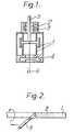
- Fig. 1 illustrates schematically a furnace arrangement for the direct nitridation of optical fibre surfaces.
- the furnace illustrated is of the carbon resistance type with carbon hearths and element 1 and has a top gas injection means including a port 2 for the introduction of a furnace purge gas and a port 3 for the introduction of a chosen recipe of reactive gases (nitriding atmosphere) into the furnace atmosphere. All gases exiting the furnace are extracted using a radial port 4.
- a silica based optical fibre preform 5 is, in use of the furnace, drawn into fibre 6 in the conventional manner.
- the reactive gas may comprise ammonia.
- the silica based fibre 6 drawn using the furnace has its surface impregnated with nitrogen. That is, the glass surface has amounts of oxygen substituted by nitrogen in the form of oxynitrides.
- Compressive claddings comprising titania doped silica have previously been applied to silica fibres in order to yield fibres with elevated tensile strength, static fatigue due to water attack is not overcome thereby.
- titania doped silica claddings may be applied to silica glass preforms, which are subsequently drawn down to fibres.
- SiCl 4 and TiCl 4 are heated in an oxy/hydrogen flame, a SiO 2 /TiO 2 soot results.
- the size and SiO 2 :TiO 2 ratio of the soot can be controlled by controlling the various gas flow-rates passing through the oxy/hydrogen torch.
- a glass preform 7 (Fig. 2) can be coated with the SiO 2 /TiO 2 soot 8 by rotating it across the flame of the oxy/hydrogen torch 9 and traversing the torch along the length of the preform.
- the fragile soot adheres loosely to the glass preform when first deposited and may be immediately sintered into compact glass under the action of a heat source, which may be the deposition torch itself.
- the soot can be sintered during drawing into fibre in the drawing furnace.
- Ti0 2 in solution with Si0 2 in low concentrations is a low, or negative, expansion glass.
- a 125pm silica glass fibre has a thin ( ⁇ 5 ⁇ m) layer of this glass over its surface, the "silica bulk" of the fibre draws the TiO 2/ SiO 2 surface into compression, yielding, as mentioned above, a fibre with elevated tensile strength but still subject to water attack.
- the water attack problem can be eliminated by producing a very thin layer ( ⁇ 200 ⁇ ) of silicon oxynitride or silicon nitride over the glass fibre.
- Ammonia is able to substitute nitrogen for oxygen in SiO 2 or Ti0 2 . Therefore in one way of obtaining the silicon oxynitride or nitride layer it is proposed that during the deposition process the torch also injects NH 3 into the vapour stream to yield a soot of silica/titania oxynitride/nitride.
- the soot is applied to a preform and processed in a similar manner to that described above, resulting in an optical fibre with high strength and high retention of strength.
- the titania/silica glass contains nitrogen at the molecular level.
- the gas flows to the oxyhydrogen torch may be as follows: TiCl 4 198cc min -1 ; SiCl 4 185cc min -1 ; H 2 4 to 20 litres min -1 , O 2 2 to 10 litres mi (the actual 0 2 and H 2 values depend on the level of sinter required); and NH 3 200cc min 1 . Without the ammonia the glass obtained is SiO 2 / ⁇ 3%TiO 2 .
- the torch is specially designed in order to burn a predetermined ratio of titanium and silicon tetrachloride vapours in an oxy/hydrogen flame to produce the aforementioned soot.
- the torch provides the reactants and heat for the reactions:
- the torch also burns to produce heat which sinters the TiO 2 /SiO 2 soot onto the surface of the silica preform.
- the silicon oxynitride or nitride layer may be produced after the Si0 2 /Ti0 2 soot as a separate process, in which case the soot applied to the preform may be only partially sintered prior to direct nitridation and drawing in a furnace as described above with respect to Fig. 1, for example.
- the ratio of coating thickness must be carefully chosen to effect the maximum compressive stress in the surface of the optical fibre.
- a compressive stress can result in the surface of an optical fibre (silica based) because silica containing traces of titania can exhibit significantly lower thermal expansion coefficients than silica glass.
- the glass containing titania can also exhibit a slightly high glass transition temperature. Therefore, as an optical fibre is drawn from its preform and freezes in, the bulk of the fibre will contract and compress the low contraction surface.
Abstract
Description
- This invention relates to optical fibres and, in particular, to the manufacture of optical fibres.
- According to one aspect of the present invention there is provided a method of manufacturing silica optical fibre characterised by the step of directly nitriding the surface of a silica preform (5) or fibre (6).
- According to another aspect of the present invention there is provided a method of providing a silica optical fibre with a silicon nitride or silicon oxynitride layer thereon characterised by the step of direct nitridation of the surface of the fibre (6) or a preform (5) from which the fibre (6) is to be drawn.
- Embodiments of the present invention will now be described with reference to the accompanying drawings, in which:
- Fig. 1 shows schematically a furnace arrangement for the direct nitridation of the surface of optical fibres, and
- Fig. 2 shows schematically the production of a preform for optical fibres with a surface layer of silicon oxynitride under compressive loading.
- Optical fibres with a thin surface layer of silicon nitride or silicon oxynitride are known to show significant improvements in static fatigue performance as stress corrosion due to water attack is retarded. More recently, such surface layers have been found to be very effective barriers to the diffusion of free hydrogen into optical fibres. The thickness of the coating required is of the order of 2ooR. The methods of production of such known silicon nitride or silicon oxynitride layers on optical fibres involve chemical vapour phase (CVD) techniques.
- The basic method proposed by the present invention, involves direct nitridation of the silicate surface of an optical fibre preform (or a fibre) to a silicon oxynitride based surface, rather than the CVD techniques referred to above. The glass is converted in the presence of a reducing and nitriding atmosphere at high temperature (-900°C). Direct nitridation, in order to produce a surface layer of silicon oxynitride on nitride on the surface of silica, is a surface modification technique. That is the existing silica surface is chemically changed, as opposed to CVD methods which deposit further material onto a surface.
- Fig. 1 illustrates schematically a furnace arrangement for the direct nitridation of optical fibre surfaces. The furnace illustrated is of the carbon resistance type with carbon hearths and element 1 and has a top gas injection means including a
port 2 for the introduction of a furnace purge gas and aport 3 for the introduction of a chosen recipe of reactive gases (nitriding atmosphere) into the furnace atmosphere. All gases exiting the furnace are extracted using a radial port 4. A silica based optical fibre preform 5 is, in use of the furnace, drawn intofibre 6 in the conventional manner. Typically the reactive gas may comprise ammonia. The silica basedfibre 6 drawn using the furnace has its surface impregnated with nitrogen. That is, the glass surface has amounts of oxygen substituted by nitrogen in the form of oxynitrides. - Compressive claddings comprising titania doped silica have previously been applied to silica fibres in order to yield fibres with elevated tensile strength, static fatigue due to water attack is not overcome thereby. Such titania doped silica claddings may be applied to silica glass preforms, which are subsequently drawn down to fibres. When SiCl4 and TiCl4 are heated in an oxy/hydrogen flame, a SiO2/TiO2 soot results. The size and SiO2:TiO2 ratio of the soot can be controlled by controlling the various gas flow-rates passing through the oxy/hydrogen torch.
- A glass preform 7 (Fig. 2) can be coated with the SiO2 /TiO2 soot 8 by rotating it across the flame of the oxy/hydrogen torch 9 and traversing the torch along the length of the preform. The fragile soot adheres loosely to the glass preform when first deposited and may be immediately sintered into compact glass under the action of a heat source, which may be the deposition torch itself. Alternatively, the soot can be sintered during drawing into fibre in the drawing furnace.
- Ti02 in solution with Si02 in low concentrations (Ti02 10%wt) is a low, or negative, expansion glass. When, for example, a 125pm silica glass fibre has a thin (~5µm) layer of this glass over its surface, the "silica bulk" of the fibre draws the TiO2/SiO2 surface into compression, yielding, as mentioned above, a fibre with elevated tensile strength but still subject to water attack. The water attack problem can be eliminated by producing a very thin layer (~200Å) of silicon oxynitride or silicon nitride over the glass fibre.
- Ammonia is able to substitute nitrogen for oxygen in SiO2 or Ti02. Therefore in one way of obtaining the silicon oxynitride or nitride layer it is proposed that during the deposition process the torch also injects NH3 into the vapour stream to yield a soot of silica/titania oxynitride/nitride. The soot is applied to a preform and processed in a similar manner to that described above, resulting in an optical fibre with high strength and high retention of strength. The titania/silica glass contains nitrogen at the molecular level.
- Typically the gas flows to the oxyhydrogen torch may be as follows: TiCl4 198cc min-1; SiCl4 185cc min-1; H2 4 to 20 litres min-1,
O 2 2 to 10 litres mi (the actual 02 and H2 values depend on the level of sinter required); and NH3 200cc min 1. Without the ammonia the glass obtained is SiO2/~3%TiO2. The torch is specially designed in order to burn a predetermined ratio of titanium and silicon tetrachloride vapours in an oxy/hydrogen flame to produce the aforementioned soot. The torch provides the reactants and heat for the reactions:

- The torch also burns to produce heat which sinters the TiO2/SiO2 soot onto the surface of the silica preform.
- Alternatively, the silicon oxynitride or nitride layer may be produced after the Si02/Ti02 soot as a separate process, in which case the soot applied to the preform may be only partially sintered prior to direct nitridation and drawing in a furnace as described above with respect to Fig. 1, for example. In both cases, the ratio of coating thickness must be carefully chosen to effect the maximum compressive stress in the surface of the optical fibre. A compressive stress can result in the surface of an optical fibre (silica based) because silica containing traces of titania can exhibit significantly lower thermal expansion coefficients than silica glass. The glass containing titania can also exhibit a slightly high glass transition temperature. Therefore, as an optical fibre is drawn from its preform and freezes in, the bulk of the fibre will contract and compress the low contraction surface.
Claims (10)
Priority Applications (1)
| Application Number | Priority Date | Filing Date | Title |
|---|---|---|---|
| AT85306478T ATE40978T1 (en) | 1984-09-29 | 1985-09-12 | OPTICAL FIBERS. |
Applications Claiming Priority (2)
| Application Number | Priority Date | Filing Date | Title |
|---|---|---|---|
| GB8424641 | 1984-09-29 | ||
| GB08424641A GB2164934B (en) | 1984-09-29 | 1984-09-29 | Optical fibres |
Publications (2)
| Publication Number | Publication Date |
|---|---|
| EP0177206A1 true EP0177206A1 (en) | 1986-04-09 |
| EP0177206B1 EP0177206B1 (en) | 1989-03-01 |
Family
ID=10567453
Family Applications (1)
| Application Number | Title | Priority Date | Filing Date |
|---|---|---|---|
| EP85306478A Expired EP0177206B1 (en) | 1984-09-29 | 1985-09-12 | Optical fibres |
Country Status (10)
| Country | Link |
|---|---|
| US (2) | US5102438A (en) |
| EP (1) | EP0177206B1 (en) |
| JP (1) | JPS6186435A (en) |
| AT (1) | ATE40978T1 (en) |
| AU (2) | AU574225B2 (en) |
| DE (1) | DE3568418D1 (en) |
| DK (1) | DK440385A (en) |
| GB (1) | GB2164934B (en) |
| IN (1) | IN165754B (en) |
| ZA (1) | ZA857466B (en) |
Cited By (1)
| Publication number | Priority date | Publication date | Assignee | Title |
|---|---|---|---|---|
| WO2011109263A1 (en) * | 2010-03-02 | 2011-09-09 | Corning Incorporated | High numerical aperture multimode optical fiber |
Families Citing this family (15)
| Publication number | Priority date | Publication date | Assignee | Title |
|---|---|---|---|---|
| US5226940A (en) * | 1987-01-23 | 1993-07-13 | Siemens Aktiengesellschaft | Process for producing optical fibers of high tensile strength |
| DE3731604A1 (en) * | 1987-09-19 | 1989-03-30 | Philips Patentverwaltung | METHOD FOR PRODUCING A MONOMODE LIGHT FIBER |
| US5269825A (en) * | 1989-04-28 | 1993-12-14 | Fujikura, Ltd. | Method of manufacturing radiation-resistant optical fiber |
| US5114738A (en) * | 1990-07-20 | 1992-05-19 | The United States Of America As Represented By The Secretary Of The Army | Direct optical fiber glass formation techniques using chemically and/or physically removable filamentary substrates |
| JP2798486B2 (en) * | 1990-08-01 | 1998-09-17 | 住友電気工業株式会社 | Method and apparatus for producing hermetic coated optical fiber |
| US5059229A (en) * | 1990-09-24 | 1991-10-22 | Corning Incorporated | Method for producing optical fiber in a hydrogen atmosphere to prevent attenuation |
| US5256177A (en) * | 1991-01-15 | 1993-10-26 | Corning Incorporated | Method for coating optical fibers |
| FR2677349B1 (en) * | 1991-06-05 | 1993-09-10 | Cabloptic Sa | METHOD FOR MANUFACTURING AN OPTICAL FIBER. |
| US5241615A (en) * | 1992-06-18 | 1993-08-31 | Corning Incorporated | Optical waveguide fiber with very thin titania-silica outer cladding layer |
| EP0867414A1 (en) | 1997-03-27 | 1998-09-30 | Alcatel | Graphite liner and heating element impregnated with vitreous carbon for a furnace for drawing optical fibers |
| WO2000030987A1 (en) * | 1998-11-24 | 2000-06-02 | Corning Incorporated | Method of applying protective coating to silica-containing article |
| US6767579B1 (en) | 1998-11-24 | 2004-07-27 | Corning Incorporated | Methods for protecting silica-containing article in optical fiber manufacturing |
| US6354113B2 (en) | 1999-01-20 | 2002-03-12 | Alcatel | Fiber optic draw furnace featuring a fiber optic preform heating and fiber drawing programmable logic controller |
| DE60033232T2 (en) | 1999-05-11 | 2007-11-15 | Atrionix Inc., Palo Alto | BALLOON ANCHOR WIRE |
| US11078669B2 (en) | 2018-03-05 | 2021-08-03 | Tamko Building Products Llc | Applying a release material to a shingle during manufacturing |
Citations (3)
| Publication number | Priority date | Publication date | Assignee | Title |
|---|---|---|---|---|
| US4118211A (en) * | 1977-06-22 | 1978-10-03 | The United States Of America As Represented By The Secretary Of The Army | Method of maintaining the strength of optical fibers |
| GB2062615A (en) * | 1979-10-04 | 1981-05-28 | Sumitomo Electric Industries | Preparing glass preform for optical transmission |
| GB1592234A (en) * | 1977-04-29 | 1981-07-01 | Int Standard Electric Corp | Sin2 coated optical fibre |
Family Cites Families (18)
| Publication number | Priority date | Publication date | Assignee | Title |
|---|---|---|---|---|
| US4030901A (en) * | 1976-07-19 | 1977-06-21 | Bell Telephone Laboratories, Incorporated | Method for drawing fibers |
| US4203744A (en) * | 1979-01-02 | 1980-05-20 | Corning Glass Works | Method of making nitrogen-doped graded index optical waveguides |
| EP0018110B1 (en) * | 1979-04-04 | 1985-10-09 | The Post Office | Optical fibre core glass, optical fibres containing such glass and process for the manufacture of such glass |
| WO1981000408A1 (en) * | 1979-07-31 | 1981-02-19 | S Ogorodnikov | Method of obtaining alkyl dioxanes-1,3 |
| WO1981000406A1 (en) * | 1979-08-03 | 1981-02-19 | Stauffer Chemical Co | Spirooxazolidines and thiazolidines as herbicide antidotes |
| US4227907A (en) * | 1979-10-22 | 1980-10-14 | The United States Of America As Represented By The Secretary Of The Army | Laser photochemical synthesis coating of optical fiber |
| US4402720A (en) * | 1980-01-22 | 1983-09-06 | Nippon Telegraph & Telephone Public Corporation | Process for preparing glass preform for optical fiber |
| FR2476058A1 (en) * | 1980-02-15 | 1981-08-21 | Quartz Silice Sa | SEMI-PRODUCT FOR THE PRODUCTION OF OPTICAL FIBERS, PROCESS FOR PREPARING THE SEMICONDUCTOR AND OPTICAL FIBERS OBTAINED FROM THE SEMICONDUCTOR |
| US4309203A (en) * | 1980-03-28 | 1982-01-05 | Kennecott Corporation | Process for manufacturing boron nitride fiber batts using a spinner |
| US4286978A (en) * | 1980-07-03 | 1981-09-01 | Corning Glass Works | Method for substantially continuously drying, consolidating and drawing an optical waveguide preform |
| FR2490211B1 (en) * | 1980-09-17 | 1990-09-21 | Passaret Michel | |
| US4388094A (en) * | 1981-12-21 | 1983-06-14 | Corning Glass Works | Method and apparatus for producing tubular glass article |
| US4501602A (en) * | 1982-09-15 | 1985-02-26 | Corning Glass Works | Process for making sintered glasses and ceramics |
| US4574063A (en) * | 1983-05-09 | 1986-03-04 | Corning Glass Works | Method of forming glass or ceramic article |
| DE3324539A1 (en) * | 1983-07-07 | 1985-01-17 | Siemens AG, 1000 Berlin und 8000 München | METHOD FOR PRODUCING GLASS BY DEPOSITION FROM THE GAS PHASE |
| JPS60226422A (en) * | 1984-04-20 | 1985-11-11 | Sumitomo Electric Ind Ltd | Preparation of intermediate for single mode fiber |
| GB2159812B (en) * | 1984-06-01 | 1988-02-10 | Stc Plc | Manufacturing optical fibre |
| JPS6126532A (en) * | 1984-07-13 | 1986-02-05 | Sumitomo Electric Ind Ltd | Production of base material for optical fiber |
-
1984
- 1984-09-29 GB GB08424641A patent/GB2164934B/en not_active Expired
-
1985
- 1985-09-12 AT AT85306478T patent/ATE40978T1/en not_active IP Right Cessation
- 1985-09-12 DE DE8585306478T patent/DE3568418D1/en not_active Expired
- 1985-09-12 EP EP85306478A patent/EP0177206B1/en not_active Expired
- 1985-09-20 AU AU47657/85A patent/AU574225B2/en not_active Ceased
- 1985-09-25 IN IN783/DEL/85A patent/IN165754B/en unknown
- 1985-09-27 ZA ZA857466A patent/ZA857466B/en unknown
- 1985-09-27 DK DK440385A patent/DK440385A/en not_active Application Discontinuation
- 1985-09-28 JP JP60216071A patent/JPS6186435A/en active Pending
-
1988
- 1988-01-22 US US07/147,333 patent/US5102438A/en not_active Expired - Fee Related
- 1988-04-11 AU AU14496/88A patent/AU584009B2/en not_active Ceased
-
1989
- 1989-02-23 US US07/314,325 patent/US4911742A/en not_active Expired - Lifetime
Patent Citations (3)
| Publication number | Priority date | Publication date | Assignee | Title |
|---|---|---|---|---|
| GB1592234A (en) * | 1977-04-29 | 1981-07-01 | Int Standard Electric Corp | Sin2 coated optical fibre |
| US4118211A (en) * | 1977-06-22 | 1978-10-03 | The United States Of America As Represented By The Secretary Of The Army | Method of maintaining the strength of optical fibers |
| GB2062615A (en) * | 1979-10-04 | 1981-05-28 | Sumitomo Electric Industries | Preparing glass preform for optical transmission |
Cited By (3)
| Publication number | Priority date | Publication date | Assignee | Title |
|---|---|---|---|---|
| WO2011109263A1 (en) * | 2010-03-02 | 2011-09-09 | Corning Incorporated | High numerical aperture multimode optical fiber |
| CN102782542A (en) * | 2010-03-02 | 2012-11-14 | 康宁股份有限公司 | High numerical aperture multimode optical fiber |
| US8385703B2 (en) | 2010-03-02 | 2013-02-26 | Corning Incorporated | High numerical aperture multimode optical fiber |
Also Published As
| Publication number | Publication date |
|---|---|
| ATE40978T1 (en) | 1989-03-15 |
| AU574225B2 (en) | 1988-06-30 |
| ZA857466B (en) | 1986-05-28 |
| GB2164934B (en) | 1988-10-05 |
| EP0177206B1 (en) | 1989-03-01 |
| AU4765785A (en) | 1986-04-10 |
| US4911742A (en) | 1990-03-27 |
| AU1449688A (en) | 1988-07-07 |
| GB8424641D0 (en) | 1984-11-07 |
| GB2164934A (en) | 1986-04-03 |
| DK440385A (en) | 1986-03-30 |
| JPS6186435A (en) | 1986-05-01 |
| AU584009B2 (en) | 1989-05-11 |
| IN165754B (en) | 1990-01-06 |
| DE3568418D1 (en) | 1989-04-06 |
| US5102438A (en) | 1992-04-07 |
| DK440385D0 (en) | 1985-09-27 |
Similar Documents
| Publication | Publication Date | Title |
|---|---|---|
| US4911742A (en) | Method of manufacturing optical fibers | |
| JP3527707B2 (en) | Optical fiber preform having OH blocking layer and method for manufacturing the same | |
| JP4350168B2 (en) | Method for producing titania-doped fused silica | |
| US4082420A (en) | An optical transmission fiber containing fluorine | |
| US4161505A (en) | Process for producing optical transmission fiber | |
| US4295869A (en) | Process for producing optical transmission fiber | |
| AU741032B2 (en) | Decreased h2 sensitivity in optical fiber | |
| AU725545B2 (en) | Process for forming a titania-containing preform silica glass blank | |
| CN1159590A (en) | Improved method for producing plane optical waveguide | |
| US4298366A (en) | Graded start rods for the production of optical waveguides | |
| US4540601A (en) | Aluminum oxide optical fiber coating | |
| US6813907B2 (en) | Fluorine doping a soot preform | |
| US5238479A (en) | Method for producing porous glass preform for optical fiber | |
| KR20010043887A (en) | Method of making a glass preform | |
| GB2199320A (en) | Optical fibres | |
| US4537611A (en) | Method for manufacturing glass from the gas phase | |
| JPH0258217B2 (en) | ||
| JPH0476936B2 (en) | ||
| EP0571915B1 (en) | Apparatus for the production of hermetically coated optical fiber | |
| JPH0525818B2 (en) | ||
| JPH0225853B2 (en) | ||
| JP3517250B2 (en) | Method for producing glass fiber preform for optical transmission line | |
| CN85101855A (en) | The production method of highly pure glass preform for optical fiber | |
| AU643451B2 (en) | Method for producing porous glass preform for optical fiber | |
| JPS6385023A (en) | Production of optical fiber |
Legal Events
| Date | Code | Title | Description |
|---|---|---|---|
| PUAI | Public reference made under article 153(3) epc to a published international application that has entered the european phase |
Free format text: ORIGINAL CODE: 0009012 |
|
| AK | Designated contracting states |
Kind code of ref document: A1 Designated state(s): AT BE CH DE FR IT LI LU NL SE |
|
| 17P | Request for examination filed |
Effective date: 19860523 |
|
| 17Q | First examination report despatched |
Effective date: 19870327 |
|
| ITF | It: translation for a ep patent filed |
Owner name: TOP - PATENTS - ITALO INCOLLINGO |
|
| GRAA | (expected) grant |
Free format text: ORIGINAL CODE: 0009210 |
|
| AK | Designated contracting states |
Kind code of ref document: B1 Designated state(s): AT BE CH DE FR IT LI LU NL SE |
|
| PG25 | Lapsed in a contracting state [announced via postgrant information from national office to epo] |
Ref country code: NL Effective date: 19890301 Ref country code: LI Effective date: 19890301 Ref country code: CH Effective date: 19890301 Ref country code: BE Effective date: 19890301 Ref country code: AT Effective date: 19890301 |
|
| REF | Corresponds to: |
Ref document number: 40978 Country of ref document: AT Date of ref document: 19890315 Kind code of ref document: T |
|
| REF | Corresponds to: |
Ref document number: 3568418 Country of ref document: DE Date of ref document: 19890406 |
|
| ET | Fr: translation filed | ||
| REG | Reference to a national code |
Ref country code: CH Ref legal event code: PL |
|
| NLV1 | Nl: lapsed or annulled due to failure to fulfill the requirements of art. 29p and 29m of the patents act | ||
| PG25 | Lapsed in a contracting state [announced via postgrant information from national office to epo] |
Ref country code: SE Effective date: 19890913 |
|
| PG25 | Lapsed in a contracting state [announced via postgrant information from national office to epo] |
Ref country code: LU Free format text: LAPSE BECAUSE OF NON-PAYMENT OF DUE FEES Effective date: 19890930 |
|
| RAP2 | Party data changed (patent owner data changed or rights of a patent transferred) |
Owner name: STC PLC |
|
| PLBE | No opposition filed within time limit |
Free format text: ORIGINAL CODE: 0009261 |
|
| STAA | Information on the status of an ep patent application or granted ep patent |
Free format text: STATUS: NO OPPOSITION FILED WITHIN TIME LIMIT |
|
| 26N | No opposition filed | ||
| REG | Reference to a national code |
Ref country code: FR Ref legal event code: EM |
|
| PG25 | Lapsed in a contracting state [announced via postgrant information from national office to epo] |
Ref country code: DE Effective date: 19900601 |
|
| REG | Reference to a national code |
Ref country code: FR Ref legal event code: TP |
|
| EUG | Se: european patent has lapsed |
Ref document number: 85306478.0 Effective date: 19900521 |
|
| PGFP | Annual fee paid to national office [announced via postgrant information from national office to epo] |
Ref country code: FR Payment date: 20010817 Year of fee payment: 17 |
|
| PG25 | Lapsed in a contracting state [announced via postgrant information from national office to epo] |
Ref country code: FR Free format text: LAPSE BECAUSE OF NON-PAYMENT OF DUE FEES Effective date: 20030603 |
|
| REG | Reference to a national code |
Ref country code: FR Ref legal event code: ST |