EP0177119A2 - Automatisches Vakuumdichtheitsprüfverfahren - Google Patents
Automatisches Vakuumdichtheitsprüfverfahren Download PDFInfo
- Publication number
- EP0177119A2 EP0177119A2 EP85304664A EP85304664A EP0177119A2 EP 0177119 A2 EP0177119 A2 EP 0177119A2 EP 85304664 A EP85304664 A EP 85304664A EP 85304664 A EP85304664 A EP 85304664A EP 0177119 A2 EP0177119 A2 EP 0177119A2
- Authority
- EP
- European Patent Office
- Prior art keywords
- chamber
- sterilizer
- time
- vacuum
- pressure
- Prior art date
- Legal status (The legal status is an assumption and is not a legal conclusion. Google has not performed a legal analysis and makes no representation as to the accuracy of the status listed.)
- Withdrawn
Links
Images

Classifications
-
- A—HUMAN NECESSITIES
- A61—MEDICAL OR VETERINARY SCIENCE; HYGIENE
- A61L—METHODS OR APPARATUS FOR STERILISING MATERIALS OR OBJECTS IN GENERAL; DISINFECTION, STERILISATION OR DEODORISATION OF AIR; CHEMICAL ASPECTS OF BANDAGES, DRESSINGS, ABSORBENT PADS OR SURGICAL ARTICLES; MATERIALS FOR BANDAGES, DRESSINGS, ABSORBENT PADS OR SURGICAL ARTICLES
- A61L2/00—Methods or apparatus for disinfecting or sterilising materials or objects other than foodstuffs or contact lenses; Accessories therefor
- A61L2/24—Apparatus using programmed or automatic operation
-
- A—HUMAN NECESSITIES
- A61—MEDICAL OR VETERINARY SCIENCE; HYGIENE
- A61L—METHODS OR APPARATUS FOR STERILISING MATERIALS OR OBJECTS IN GENERAL; DISINFECTION, STERILISATION OR DEODORISATION OF AIR; CHEMICAL ASPECTS OF BANDAGES, DRESSINGS, ABSORBENT PADS OR SURGICAL ARTICLES; MATERIALS FOR BANDAGES, DRESSINGS, ABSORBENT PADS OR SURGICAL ARTICLES
- A61L2/00—Methods or apparatus for disinfecting or sterilising materials or objects other than foodstuffs or contact lenses; Accessories therefor
- A61L2/26—Accessories or devices or components used for biocidal treatment
- A61L2/28—Devices for testing the effectiveness or completeness of sterilisation, e.g. indicators which change colour
-
- G—PHYSICS
- G01—MEASURING; TESTING
- G01M—TESTING STATIC OR DYNAMIC BALANCE OF MACHINES OR STRUCTURES; TESTING OF STRUCTURES OR APPARATUS, NOT OTHERWISE PROVIDED FOR
- G01M3/00—Investigating fluid-tightness of structures
- G01M3/02—Investigating fluid-tightness of structures by using fluid or vacuum
- G01M3/26—Investigating fluid-tightness of structures by using fluid or vacuum by measuring rate of loss or gain of fluid, e.g. by pressure-responsive devices, by flow detectors
- G01M3/32—Investigating fluid-tightness of structures by using fluid or vacuum by measuring rate of loss or gain of fluid, e.g. by pressure-responsive devices, by flow detectors for containers, e.g. radiators
- G01M3/34—Investigating fluid-tightness of structures by using fluid or vacuum by measuring rate of loss or gain of fluid, e.g. by pressure-responsive devices, by flow detectors for containers, e.g. radiators by testing the possibility of maintaining the vacuum in containers, e.g. in can-testing machines
Definitions
- the present invention relates to an automatic method for testing the vacuum leak rate of a sterilizer.
- the conventional method of testing a sterilizer for leaks is to draw a vacuum, hold it and manually measure the change in pressure over time to calculate a leak rate.
- a stop watch is generally used to measure the time.
- a pressure reading is taken at a time, t 1 , and again at a time, t 2 .
- the manual testing method lends itself to both equipment and human error. Monitoring a sterilizer over a period of time by different technicians using different watches does not yield long term reproducible results.
- the present invention provides an automatic method for testing the air leak rate in a sterilizer which will provide standardized, reproducible results over a period of time and which can be easily operated without extra equipment.
- a method for automatically testing the vacuum leak rate of the sterilizer includes the step of preprogramming the control assembly to effect a sequence of sterilizer operations.
- the sterilizer operations include removing a predetermined quantity of fluid by drawing a vacuum from the chamber and heating the sterilizer, drawing a vacuum in the chamber to a predetermined level for standardizing test starting points, isolating the chamber at the predetermined vacuum level, preferably about fifty millimeters Hg absolute, for a first predetermined period of time sufficient to permit stabilization of the sterilizer conditions, and maintaining the chamber in isolation for a second predetermined period of time is marked by an initial point in time and an end point in time.
- the sequence of operations further includes detecting and recording the absolute pressure within the chamber at each of the initial and end points in time of the second predetermined period of time, returning the chamber to atmospheric pressure, preferably by the admission of ambient atmospheric air, and calculating the difference between the absolute pressure detected at the initial and end points of time over the second predetermined period of time to provide the vacuum leak rate of the sterilizer.
- the air removal and sterilizer heating operation includes subjecting the chamber to a plurality of cyclic pressure pulses.
- Each pressure pulse includes a pressurization phase wherein a condensable vapor having trasferable latent heat, preferably steam, is injected into the chamber to elevate the pressure within the chamber, and an evacuation phase wherein the vapor is removed from the chamber to decrease the pressure within the chamber.
- the plurality of pressure pulses are sufficient to remove the predetermined quantity of fluid from the chamber and to heat the sterilizer to the predetermined normal working temperature.
- the vacuum level in the chamber is also preferably detected and recorded upon completion of the drawing operation and the predetermined vacuum level so detected is preferably employed by the control assembly to effect advance of the sequence to the chamber isolating operation.
- the completion of the first predetermined period of time, preferably about five minutes, of the chamber isolating operation is preferably employed by the control assembly to effect advance of the sequence to the chamber isolation maintenance operation.
- the completion of the second predetermined period of time, preferably about ten minutes, is preferably employed by the control assembly to effect advance of the sequence to the atmospheric pressure return operation.
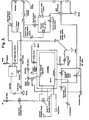
- FIG. 1 illustrates the method for testing the vacuum leak rate of a sterilizer provided by the present invention.
- Sterilizer 10 includes inner walled structure 14 and outer walled structure 18. Chamber 16 is defined within the inner walled structure 14. Steam jacket 20 is defined between outer walled structure 18 and inner walled structure 14.
- Sterile filterd air is provided from an air source which passes through air filters 60, solenoid valve 62 and one way check valve 64 to inlet 66.
- Steam is provided from a source of steam, such as a boiler (not shown), and is delivered through conduit 72 to steam jacket 20.
- a steam supply valve 56 and a steam pressure regulator 74 control the flow of steam through conduit 72.
- the steam enters chamber 16 through conduit 68, solenoid valve 70 and inlet 66.
- a pressure guage 54 and pressure sensing means, or transducer 90 are provided.
- the chamber evacuation is achieved by means of the vacuum ejector 84 which is supplied with water by supply valve 104, check valve 106 and vacuum solenoid valve 108. Flow of water through the ejector 84 creates suction in the end of drain 30 and along drain line 44 to evacuate the chamber 16.
- An optional water source 80 and pump 82 may be provided to accommodate those locations not having readily accessable sources of pressurized water to which to connect the sterilizer 10.
- the steps of the vacuum leak test are preset and automatically controlled by a control assembly which includes the microcomputer, controller and factory set logic switches shown in the diagram of FIG. 2. At least four lines of communication relay information from the microcomputer to the controller, vacuum switch 1, vacuum switch 2, pressure switch 1 and pressure switch 2. A fifth line communicates the information from the controller to the microcomputer that the cycle has begun. Additional lines for communicating temperature information are also provided.
- the logic set switches for pressure, vacuum and temperature are preset, at the factory, according to the levels of pressure, vacuum and temperature which have been determined to be desirable for effecting operation changes in the cycle when the pressure/vacuum sensing means, such as transducer 90, or the temperature sensing means detect levels within the sterilizer.
- the information is communicated to the microcomputer.
- the microcomputer relays the information by means of the appropriate lines to the controller. which in turn activates the appropriate valve to alter the sterilizer operations.
- the consequent altered conditions are in turn detected by the appropriate transducers which continue to communicate the information to the microcomputer.
- L.E.D displays and a printer for recording the conditions and, for purposes of the present invention, the leak test results, are also provided.
- the leak test includes the following general steps: the air removal step; the stabilization step; the vacuum hold step; and the air return to atmospheric pressure step.
- the leak test must be carried out when the sterilizer 10 is at its normal working temperature.
- the chamber 16 is therefore subjected to a plurality of cyclic pressure/vacuum pulses which alternately pressurize the chamber for a predetermined period then evacuate the chamber to at least a predetermined minimum vacuum level and for at least a predetermined minimum evacuation time.
- the precise number of pressure/vacuum pulses and the level of vacuum achieved in each evacuation phase is not critical provided a sufficient amount of air is removed from chamber 16 and the associated piping and chamber 16 and its associated piping are heated to the normal working temperature of the sterilizer.
- the chamber 16 is pressurized during the pressurization phase of each pulse by a condensable vapor having transferable latent heat, such as steam.
- a condensable vapor having transferable latent heat such as steam.
- the leak test is started by switching the power on, locking the sterilization chamber door (not shown) and selecting the cycle.
- the door lock is preferably automatically controlled.
- the remainder of the leak test is automatically controlled and proceeds without human intervention to the end of the test at step 4.
- valve 62 is open, and valves 70, 38, 86 and 108 are open.
- the optional water pump 82 operates throughout the test procedure. Steam is admitted into chamber 16 through inlet 66 for sixty seconds. Then, valve 70 is closed and valve 62 is closed. A vacuum is drawn in the chamber 16 to about ten inches Hg. When the chamber reaches approximately 3-4 psig during the first evacuation pulse, pressure switch 2 drops out, valve 86 is closed, and the vacuum timer begins to run for one minute. When one minute has passed and ten inches Hg has been reached, valves 38 and 108 are closed. Valve 70 is opened to again admit steam to chamber 16 to a level of approximately 26 psig.
- valve 70 closes and valves 38, 86 and 108 open to draw another vacuum.
- valve 86 closes and the vacuum timer again runs for at least one minute until a vacuum of ten inches Hg is achieved, after which valves 38 and 108 close and valve 70 again opens to admit steam into chamber 16 until a pressure of about 26 psig is achieved.
- the pressure/vacuum pulses continue in that manner with the exception that progressively deeper vacuums are drawn with each proceeding evacuation pulse to a final preset vacuum level of at least 40-50 mm Hg.
- step 2 proceeds. For a predetermined period of time, about five minutes, all valves are closed and the chamber is isolated. The vacuum drawing means is stopped. The vacuum level at this stage is detected and automatically recorded by the printer.
- the chamber conditions stabilize.
- the chamber, piping and valve temperatures and the electronic control temperatures, specifically the transducers for sensing conditions stabilize. Any moisture remaining in the chamber and connecting piping will evaporate, providing an absolute pressure rise. At the end of step 2 the pressure may have stabilized to about 50 mm Hg.
- the 40-50 mm Hg level is not critical to the test provided testing always occurs at the same level of vacuum at the end of step 2 to ensure consistency of measurement.
- certain regulatory bodies specifically, the Department of Health and Social Security in the United Kingdom, do specify vacuum testing levels of at least 50 mm Hg.
- the specific level preset by the automatic controls may vary according to local regulations and practices.
- the pressure and time settings can be set to the limits of a particular machine.
- step 3 begins and the absolute pressure of the chamber 16 is automatically detected, recorded and printed on the sterilizer readout.
- Step 3 the vacuum hold period proceeds for a predetermined period of time, preferably about ten minutes. All valves remain closed.
- the pressure sensing means, transducer 90 measures the pressure drift between two points in time at the beginning and end of the ten minute period. The absolute pressure is again automatically recorded on the sterilizer printout.
- step 3 At the end of the predetermined period of time in step 3, ambienc atmospheric air is admitted into the chamber 16 to return it to atmospheric pressure through valve 62. At the end of step 4, valve 38 is opened.
- the leak rate is calculated automatically by the difference in absolute pressure readings taken at the two points in time at the beginning and end of the predetermined ten minute vacuum hold period in step 3, over that predetermined period of time.
Landscapes
- Health & Medical Sciences (AREA)
- Epidemiology (AREA)
- Life Sciences & Earth Sciences (AREA)
- Animal Behavior & Ethology (AREA)
- General Health & Medical Sciences (AREA)
- Public Health (AREA)
- Veterinary Medicine (AREA)
- Physics & Mathematics (AREA)
- General Physics & Mathematics (AREA)
- Apparatus For Disinfection Or Sterilisation (AREA)
- Examining Or Testing Airtightness (AREA)
Applications Claiming Priority (2)
| Application Number | Priority Date | Filing Date | Title |
|---|---|---|---|
| US65839784A | 1984-10-05 | 1984-10-05 | |
| US658397 | 1991-02-20 |
Publications (2)
| Publication Number | Publication Date |
|---|---|
| EP0177119A2 true EP0177119A2 (de) | 1986-04-09 |
| EP0177119A3 EP0177119A3 (de) | 1987-01-07 |
Family
ID=24641082
Family Applications (1)
| Application Number | Title | Priority Date | Filing Date |
|---|---|---|---|
| EP85304664A Withdrawn EP0177119A3 (de) | 1984-10-05 | 1985-07-01 | Automatisches Vakuumdichtheitsprüfverfahren |
Country Status (1)
| Country | Link |
|---|---|
| EP (1) | EP0177119A3 (de) |
Cited By (11)
| Publication number | Priority date | Publication date | Assignee | Title |
|---|---|---|---|---|
| EP0290929A2 (de) * | 1987-05-15 | 1988-11-17 | Siemens Aktiengesellschaft | Automatischer Sterilisierapparat |
| EP0424128A2 (de) * | 1989-10-20 | 1991-04-24 | Smiths Industries Public Limited Company | Autoklave |
| EP0654274A1 (de) * | 1993-11-19 | 1995-05-24 | M.O.COM. S.r.L. | Sterilisierungsverfahren und Anlage für einen Dampfautoklav |
| EP0834324A2 (de) * | 1996-10-04 | 1998-04-08 | JOHNSON & JOHNSON MEDICAL, INC. | Verfahren und Vorrichtung zur Detektion von eingeschlossenem Wasser in einer Vakuumkammer |
| GB2327613A (en) * | 1997-07-26 | 1999-02-03 | Smiths Industries Plc | Method and apparatus for automatically testing an autoclave |
| GB2331156A (en) * | 1997-11-08 | 1999-05-12 | Smiths Industries Plc | Leak testing in autoclaves |
| EP0916350A1 (de) * | 1997-11-08 | 1999-05-19 | Smiths Industries Public Limited Company | Autoklave |
| US6629450B2 (en) * | 2001-07-13 | 2003-10-07 | Taiwan Semiconductor Manufacturing Co., Ltd | Semiconductor auto leak rate tester |
| EP2414722A1 (de) * | 2009-05-19 | 2012-02-08 | Teva Pharmaceutical Industries Ltd. | Programmierbare kondensatableitervorrichtung |
| WO2020167428A1 (en) * | 2019-02-14 | 2020-08-20 | American Sterilizer Company | Method for pressurizing a steam sterilization chamber |
| GB2609962A (en) * | 2021-08-19 | 2023-02-22 | Atlas Copco Airpower Nv | Leak detection of vacuum systems |
Citations (2)
| Publication number | Priority date | Publication date | Assignee | Title |
|---|---|---|---|---|
| US3800586A (en) * | 1972-04-24 | 1974-04-02 | Uson Corp | Leak testing apparatus |
| US4164538A (en) * | 1977-11-11 | 1979-08-14 | American Sterilizer Company | Load conditioning control method for steam sterilization |
-
1985
- 1985-07-01 EP EP85304664A patent/EP0177119A3/de not_active Withdrawn
Patent Citations (2)
| Publication number | Priority date | Publication date | Assignee | Title |
|---|---|---|---|---|
| US3800586A (en) * | 1972-04-24 | 1974-04-02 | Uson Corp | Leak testing apparatus |
| US4164538A (en) * | 1977-11-11 | 1979-08-14 | American Sterilizer Company | Load conditioning control method for steam sterilization |
Cited By (22)
| Publication number | Priority date | Publication date | Assignee | Title |
|---|---|---|---|---|
| EP0290929A2 (de) * | 1987-05-15 | 1988-11-17 | Siemens Aktiengesellschaft | Automatischer Sterilisierapparat |
| EP0290929A3 (en) * | 1987-05-15 | 1989-06-14 | Siemens Aktiengesellschaft Berlin Und Munchen | Automatic sterilizer |
| EP0424128A2 (de) * | 1989-10-20 | 1991-04-24 | Smiths Industries Public Limited Company | Autoklave |
| EP0424128A3 (en) * | 1989-10-20 | 1991-08-14 | Smiths Industries Public Limited Company | Autoclaves |
| US5145647A (en) * | 1989-10-20 | 1992-09-08 | Smiths Industries Public Limited Co. | Autoclaves |
| EP0654274A1 (de) * | 1993-11-19 | 1995-05-24 | M.O.COM. S.r.L. | Sterilisierungsverfahren und Anlage für einen Dampfautoklav |
| EP0834324A3 (de) * | 1996-10-04 | 2000-03-22 | JOHNSON & JOHNSON MEDICAL, INC. | Verfahren und Vorrichtung zur Detektion von eingeschlossenem Wasser in einer Vakuumkammer |
| EP0834324A2 (de) * | 1996-10-04 | 1998-04-08 | JOHNSON & JOHNSON MEDICAL, INC. | Verfahren und Vorrichtung zur Detektion von eingeschlossenem Wasser in einer Vakuumkammer |
| GB2327613A (en) * | 1997-07-26 | 1999-02-03 | Smiths Industries Plc | Method and apparatus for automatically testing an autoclave |
| GB2327613B (en) * | 1997-07-26 | 2002-06-19 | Smiths Industries Plc | Autoclave apparatus |
| GB2331156A (en) * | 1997-11-08 | 1999-05-12 | Smiths Industries Plc | Leak testing in autoclaves |
| EP0916350A1 (de) * | 1997-11-08 | 1999-05-19 | Smiths Industries Public Limited Company | Autoklave |
| GB2331156B (en) * | 1997-11-08 | 2002-04-03 | Smiths Industries Plc | Autoclaves |
| US6629450B2 (en) * | 2001-07-13 | 2003-10-07 | Taiwan Semiconductor Manufacturing Co., Ltd | Semiconductor auto leak rate tester |
| EP2414722A1 (de) * | 2009-05-19 | 2012-02-08 | Teva Pharmaceutical Industries Ltd. | Programmierbare kondensatableitervorrichtung |
| EP2414722A4 (de) * | 2009-05-19 | 2013-07-10 | Teva Pharma | Programmierbare kondensatableitervorrichtung |
| US8739808B2 (en) | 2009-05-19 | 2014-06-03 | Teva Pharmaceutical Industries, Ltd. | Programmable steam trap apparatus |
| WO2020167428A1 (en) * | 2019-02-14 | 2020-08-20 | American Sterilizer Company | Method for pressurizing a steam sterilization chamber |
| US11007289B2 (en) | 2019-02-14 | 2021-05-18 | American Sterilizer Company | Method for pressurizing a steam sterilization chamber |
| AU2020222786B2 (en) * | 2019-02-14 | 2022-07-21 | American Sterilizer Company | Method for pressurizing a steam sterilization chamber |
| GB2609962A (en) * | 2021-08-19 | 2023-02-22 | Atlas Copco Airpower Nv | Leak detection of vacuum systems |
| WO2023021090A1 (en) * | 2021-08-19 | 2023-02-23 | Atlas Copco Airpower Nv Atlas | Leak detection of vacuum systems |
Also Published As
| Publication number | Publication date |
|---|---|
| EP0177119A3 (de) | 1987-01-07 |
Similar Documents
| Publication | Publication Date | Title |
|---|---|---|
| US4687635A (en) | Porous load vapor sterilization cycle | |
| US4164538A (en) | Load conditioning control method for steam sterilization | |
| EP0028542A1 (de) | Verfahren und Apparat zur Sterilisation mit Dampf | |
| US4203947A (en) | Load conditioning control apparatus for steam sterilization | |
| EP0177119A2 (de) | Automatisches Vakuumdichtheitsprüfverfahren | |
| US4203943A (en) | Method of biocidal sterilization using cyclic subatmospheric pressure conditioning | |
| US5494530A (en) | Method of and apparatus for testing and cleaning of endoscopes | |
| US4372916A (en) | Establishing and ascertaining desired air removal in steam sterilization | |
| US4238447A (en) | Steam sterilizing process | |
| US4241010A (en) | Pressure responsive conditioning control gas sterilization | |
| US4108601A (en) | Steam sterilizing apparatus | |
| US4944919A (en) | Low temperature sterilizer | |
| US8325049B2 (en) | Method and system for measuring temperature and pressure in different regions to determine steam quality | |
| JPS649863B2 (de) | ||
| US4239731A (en) | Apparatus for biocidal sterilization using cyclic subatmospheric pressure conditioning | |
| US6797233B1 (en) | Sterilization apparatus | |
| EP0015328B1 (de) | Verfahren und Vorrichtung zur Dampfsterilisation | |
| CA1284266C (en) | Apparatus for subjecting a load to a constant temperature below 100 _c in a closed chamber | |
| EP3924000B1 (de) | Verfahren zur druckbeaufschlagung einer dampfsterilisationskammer | |
| US4891188A (en) | Unplumbed sterilizer | |
| US8816865B1 (en) | Method and system for measuring temperature and pressure in different regions to determine steam quality | |
| US5364590A (en) | Method for sterilization of objects | |
| JPS643503B2 (de) | ||
| CA1121026A (en) | Load conditioning control of and method and apparatus for steam sterilization | |
| JPH11347105A (ja) | 自己診断システム付きレトルト殺菌装置 |
Legal Events
| Date | Code | Title | Description |
|---|---|---|---|
| PUAI | Public reference made under article 153(3) epc to a published international application that has entered the european phase |
Free format text: ORIGINAL CODE: 0009012 |
|
| AK | Designated contracting states |
Kind code of ref document: A2 Designated state(s): DE FR GB SE |
|
| PUAL | Search report despatched |
Free format text: ORIGINAL CODE: 0009013 |
|
| AK | Designated contracting states |
Kind code of ref document: A3 Designated state(s): DE FR GB SE |
|
| STAA | Information on the status of an ep patent application or granted ep patent |
Free format text: STATUS: THE APPLICATION IS DEEMED TO BE WITHDRAWN |
|
| 18D | Application deemed to be withdrawn |
Effective date: 19870708 |
|
| RIN1 | Information on inventor provided before grant (corrected) |
Inventor name: MIRALDI, PETER THOMAS Inventor name: MCBRIDE, RICHARD ALBERT Inventor name: KAEHLER, KRISTINE MARGARET Inventor name: NEVENS, RICHARD GRAHAM |