EP0176876B1 - Method of calcining carbonaceous bodies, in particular electrodes, in either continuous or intermittent furnaces, and a containment structure for the implementation thereof - Google Patents
Method of calcining carbonaceous bodies, in particular electrodes, in either continuous or intermittent furnaces, and a containment structure for the implementation thereof Download PDFInfo
- Publication number
- EP0176876B1 EP0176876B1 EP85111845A EP85111845A EP0176876B1 EP 0176876 B1 EP0176876 B1 EP 0176876B1 EP 85111845 A EP85111845 A EP 85111845A EP 85111845 A EP85111845 A EP 85111845A EP 0176876 B1 EP0176876 B1 EP 0176876B1
- Authority
- EP
- European Patent Office
- Prior art keywords
- sidewalls
- layer
- sideways
- border
- yielding
- Prior art date
- Legal status (The legal status is an assumption and is not a legal conclusion. Google has not performed a legal analysis and makes no representation as to the accuracy of the status listed.)
- Expired
Links
Images

Classifications
-
- F—MECHANICAL ENGINEERING; LIGHTING; HEATING; WEAPONS; BLASTING
- F27—FURNACES; KILNS; OVENS; RETORTS
- F27D—DETAILS OR ACCESSORIES OF FURNACES, KILNS, OVENS OR RETORTS, IN SO FAR AS THEY ARE OF KINDS OCCURRING IN MORE THAN ONE KIND OF FURNACE
- F27D3/00—Charging; Discharging; Manipulation of charge
- F27D3/12—Travelling or movable supports or containers for the charge
- F27D3/123—Furnace cars
-
- C—CHEMISTRY; METALLURGY
- C04—CEMENTS; CONCRETE; ARTIFICIAL STONE; CERAMICS; REFRACTORIES
- C04B—LIME, MAGNESIA; SLAG; CEMENTS; COMPOSITIONS THEREOF, e.g. MORTARS, CONCRETE OR LIKE BUILDING MATERIALS; ARTIFICIAL STONE; CERAMICS; REFRACTORIES; TREATMENT OF NATURAL STONE
- C04B35/00—Shaped ceramic products characterised by their composition; Ceramics compositions; Processing powders of inorganic compounds preparatory to the manufacturing of ceramic products
- C04B35/515—Shaped ceramic products characterised by their composition; Ceramics compositions; Processing powders of inorganic compounds preparatory to the manufacturing of ceramic products based on non-oxide ceramics
- C04B35/52—Shaped ceramic products characterised by their composition; Ceramics compositions; Processing powders of inorganic compounds preparatory to the manufacturing of ceramic products based on non-oxide ceramics based on carbon, e.g. graphite
- C04B35/528—Shaped ceramic products characterised by their composition; Ceramics compositions; Processing powders of inorganic compounds preparatory to the manufacturing of ceramic products based on non-oxide ceramics based on carbon, e.g. graphite obtained from carbonaceous particles with or without other non-organic components
- C04B35/532—Shaped ceramic products characterised by their composition; Ceramics compositions; Processing powders of inorganic compounds preparatory to the manufacturing of ceramic products based on non-oxide ceramics based on carbon, e.g. graphite obtained from carbonaceous particles with or without other non-organic components containing a carbonisable binder
-
- C—CHEMISTRY; METALLURGY
- C25—ELECTROLYTIC OR ELECTROPHORETIC PROCESSES; APPARATUS THEREFOR
- C25C—PROCESSES FOR THE ELECTROLYTIC PRODUCTION, RECOVERY OR REFINING OF METALS; APPARATUS THEREFOR
- C25C3/00—Electrolytic production, recovery or refining of metals by electrolysis of melts
- C25C3/06—Electrolytic production, recovery or refining of metals by electrolysis of melts of aluminium
- C25C3/08—Cell construction, e.g. bottoms, walls, cathodes
- C25C3/12—Anodes
- C25C3/125—Anodes based on carbon
-
- F—MECHANICAL ENGINEERING; LIGHTING; HEATING; WEAPONS; BLASTING
- F27—FURNACES; KILNS; OVENS; RETORTS
- F27B—FURNACES, KILNS, OVENS OR RETORTS IN GENERAL; OPEN SINTERING OR LIKE APPARATUS
- F27B9/00—Furnaces through which the charge is moved mechanically, e.g. of tunnel type; Similar furnaces in which the charge moves by gravity
- F27B9/06—Furnaces through which the charge is moved mechanically, e.g. of tunnel type; Similar furnaces in which the charge moves by gravity heated without contact between combustion gases and charge; electrically heated
- F27B9/08—Furnaces through which the charge is moved mechanically, e.g. of tunnel type; Similar furnaces in which the charge moves by gravity heated without contact between combustion gases and charge; electrically heated heated through chamber walls
-
- Y—GENERAL TAGGING OF NEW TECHNOLOGICAL DEVELOPMENTS; GENERAL TAGGING OF CROSS-SECTIONAL TECHNOLOGIES SPANNING OVER SEVERAL SECTIONS OF THE IPC; TECHNICAL SUBJECTS COVERED BY FORMER USPC CROSS-REFERENCE ART COLLECTIONS [XRACs] AND DIGESTS
- Y02—TECHNOLOGIES OR APPLICATIONS FOR MITIGATION OR ADAPTATION AGAINST CLIMATE CHANGE
- Y02P—CLIMATE CHANGE MITIGATION TECHNOLOGIES IN THE PRODUCTION OR PROCESSING OF GOODS
- Y02P10/00—Technologies related to metal processing
- Y02P10/25—Process efficiency
Definitions
- This invention concerns a method of calcining carbonaceous bodies, in particular electrodes, in either continuous or intermittent furnaces, and a containment structure for the implementation thereof.
- this invention envisages the use of a containment structure characterized in that it comprises a base frame, refractory supports placed on said frame and carrying refractory plates adapted to form the loading surface or platform, and a sideways yielding edge formation as a result of the expansion undergone by the carbonaceous bodies.
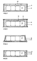
- Each of the trucks comprises a metal frame 1 on which modular hollow base supports 2 are made to rest which are formed from a refractory material.
- Such base supports 2 are essentially in the form of columns and provided with stepped grooves adapted to receive beams 3 thereon which form in combination a rest grid for loading plates 4.
- Elements 5 rest on the peripheral base supports 2 which extend with vertical or upstanding pillars 6 provided with longitudinal flutes confronting corresponding flutes on the adjacent pillars.
- the elements 5 resting on the peripheral base supports 2 form, in combination with the corresponding vertical pillars L-like elements which carry in pairs plates 7 forming in combination the containment sidewalls of the truck.
- the plates 7 are inserted with the vertical sides between confronting flutes of the pillars 6 and are superimposed to reach a greater combined height than the carbonaceous bodies to be calcined.
- the height of the horizontal section of the L-like elements is smaller than the height of the base support step, thereby said elements are allowed to move outwards.
- the pillars 6 and plates 7 constitute an edge formation or border which is yieldable in an outward, lateral direction.
- a layer of carbonaceous powder 8 is first laid on the loading surface of a truck, which layer forms the means of protection, for control of oxidation, and for transmission of expansion in accordance with the invention, and the electrodes 9 to be calcined are then placed onto said layer.
- a filler again comprised of carbonaceous powder, is poured over said electrodes which completely covers and surrounds them laterally.
- the truck is then moved to the furnace interior to subject the electrodes 9 to the calcining process.
- the sidewalls 6 of the truck are allowed to move in a sideways direction, thus absorbing the thrust from the expanding electrodes as the temperature rises.
- the inventive method contemplates that a plurality of evenly distributed weights 10 (see Figure 2) is placed on the filler 8 which comprise, of preference, corrosion-resistant plates of a refractory material.
- This arrangement affords the advantage that, by virtue of the provision of the weights 10 over the electrodes 9, the thrust from the internal stresses of the latter during the binder softening phase can be counteracted to prevent their deformation and possible cracking.
- the weights 10 are placed in direct contact with the top surface of the electrodes 9, and are then covered with carbonaceous powder. On the layer formed by said powder, there are placed additional lightweight plates 11 having the function of protecting the powder filler against oxidation.
- the sidewalls 12 of the border or edge formation are hinged with their bottom edge to the truck structure and set sloping inwardly or in any case held close against the filler 8.
- the walls can yield sideways and tilt part-way out, thereby the thrusts brought about by such expansion movements can be absorbed also in this case.
- a layer of a yieldable material 13 (e.g. glass wool or some other fibrous material, or polymeric foam, etc.) having the function of absorbing the expansion of the electrodes during calcination.
- the material 13 may either be a plastically or elastically yielding material, or a heat-destructable one. Depending on the chemical and physical properties of the material employed, the latter may be used in one or more passages through the furnace interior.
Landscapes
- Engineering & Computer Science (AREA)
- Chemical & Material Sciences (AREA)
- Materials Engineering (AREA)
- Mechanical Engineering (AREA)
- General Engineering & Computer Science (AREA)
- Ceramic Engineering (AREA)
- Organic Chemistry (AREA)
- Metallurgy (AREA)
- Electrochemistry (AREA)
- Chemical Kinetics & Catalysis (AREA)
- Manufacturing & Machinery (AREA)
- Combustion & Propulsion (AREA)
- Structural Engineering (AREA)
- Furnace Charging Or Discharging (AREA)
- Carbon And Carbon Compounds (AREA)
- Furnace Details (AREA)
- Electrolytic Production Of Metals (AREA)
Description
- This invention concerns a method of calcining carbonaceous bodies, in particular electrodes, in either continuous or intermittent furnaces, and a containment structure for the implementation thereof.
- Known are methods of calcining anodes in continuous furnaces. One of such prior methods (cfr. Published German Application DE-A-3042708) provides for the carbonaceous blocks (anodes) to be covered with carbonaceous powder in order to protect them against oxidation, stowed into muffles, placed onto a truck, and pushed into the furnace in accordance with a preset thermal scheme.
- During heating, and in particular in the temperature range of 300° to 500°C, there takes place a gaseous emission from the anodes of volatile organics issuing from the decomposition and/or distillation of a fraction of the binder forming the anode, in the gaseous, vapor, and particulate forms. Since the volatile substances comprise essentially aromatic hydrocarbons, said prior method has the drawback of being highly polluting.
- To obviate such a drawback, a method has been proposed (CFR. European Patent Specification EP-A-103130) wherein provisions are made for covering the carbonaceous bodies with an antioxidant protective powder and calcining them by moving through a truck furnace, in an oxidizing medium, which at the operating temperature, enables complete burning of the volatile substances within the furnace, and accordingly, the release of volatile-free gases.
- However, since the carbonaceous bodies undergo during calcination an expansion due to the temperature increase, that prior method poses the problem that the electrodes distort, crack, and often open up on account of their contacting the truck walls, the rigid structure whereof opposes the expansion thrust.
- Furthermore, owing to the chemical and physical changes undergone by the binder, pitch in this case, during calcination there form in the carbonaceous bodies cracks which deteriorate their mechanical and electrical properties.
- According to this invention, all such problems are obviated by a method of calcining carbonaceous bodies, in particular electrodes, in either continuous or intermittent furnaces by the use of containment structures in which carbonaceous bodies to be calcined are placed and then covered at least laterally with a filler as means of protection, for control of oxidation, and for transmitting expansion, characterized in that at least two sidewalls of the structure are caused to yield sideways outwards due to the expansion of the carbonaceous bodies during calcination.
- To implement the method, this invention envisages the use of a containment structure characterized in that it comprises a base frame, refractory supports placed on said frame and carrying refractory plates adapted to form the loading surface or platform, and a sideways yielding edge formation as a result of the expansion undergone by the carbonaceous bodies.
- The invention is further explained hereinafter in connection with a preferred embodiment and some modifications thereof, given herein by way of example and not of limitation with reference to the accompanying drawings, where:
- Figure 1 is a partly sectional front view of a containment structure for firing electrodes, which implements the inventive method;
- Figure 2 shows schematically in a fragmentary front sectional view, a structure with the electrodes subjected to the action of weights;
- Figure 3 is a view similar to Figure 2, showing a modified embodiment of the structure; and
- Figures 4 and 5 are views similar to Figure 2, showing two further embodiments of the structure.
- As is apparent from the drawing figures, the method of this invention envisages that carbonaceous bodies, in particular electrodes, are calcined in a continuous furnace comprised, in this instance, by a truck furnace on which the electrodes are placed, preferably in a single layer, although several layers may be viable in some cases.
- Each of the trucks comprises a metal frame 1 on which modular
hollow base supports 2 are made to rest which are formed from a refractory material. -
Such base supports 2 are essentially in the form of columns and provided with stepped grooves adapted to receivebeams 3 thereon which form in combination a rest grid forloading plates 4.Elements 5 rest on the peripheral base supports 2 which extend with vertical orupstanding pillars 6 provided with longitudinal flutes confronting corresponding flutes on the adjacent pillars. In essence, theelements 5 resting on the peripheral base supports 2 form, in combination with the corresponding vertical pillars L-like elements which carry inpairs plates 7 forming in combination the containment sidewalls of the truck. Theplates 7 are inserted with the vertical sides between confronting flutes of thepillars 6 and are superimposed to reach a greater combined height than the carbonaceous bodies to be calcined. - In particular, the height of the horizontal section of the L-like elements is smaller than the height of the base support step, thereby said elements are allowed to move outwards.
- The
pillars 6 andplates 7 constitute an edge formation or border which is yieldable in an outward, lateral direction. - In operation, a layer of
carbonaceous powder 8 is first laid on the loading surface of a truck, which layer forms the means of protection, for control of oxidation, and for transmission of expansion in accordance with the invention, and theelectrodes 9 to be calcined are then placed onto said layer. - Thereafter, a filler, again comprised of carbonaceous powder, is poured over said electrodes which completely covers and surrounds them laterally. The truck is then moved to the furnace interior to subject the
electrodes 9 to the calcining process. - During calcination, the
sidewalls 6 of the truck are allowed to move in a sideways direction, thus absorbing the thrust from the expanding electrodes as the temperature rises. - On leaving the furnace, the original structure of the truck is restored by closing back the sidewalls, and this operation may be carried out in an automated fashion.
- In a modified embodiment, the inventive method contemplates that a plurality of evenly distributed weights 10 (see Figure 2) is placed on the
filler 8 which comprise, of preference, corrosion-resistant plates of a refractory material. This arrangement affords the advantage that, by virtue of the provision of theweights 10 over theelectrodes 9, the thrust from the internal stresses of the latter during the binder softening phase can be counteracted to prevent their deformation and possible cracking. - In another embodiment of the invention (see Figure 3), the
weights 10 are placed in direct contact with the top surface of theelectrodes 9, and are then covered with carbonaceous powder. On the layer formed by said powder, there are placedadditional lightweight plates 11 having the function of protecting the powder filler against oxidation. - In these embodiments, the sidewalls of the border are allowed to translate outwardly due to the electrodes expanding.
- In a modified embodiment (see Figure 4), the
sidewalls 12 of the border or edge formation are hinged with their bottom edge to the truck structure and set sloping inwardly or in any case held close against thefiller 8. Thus, upon the electrodes beginning to expand, the walls can yield sideways and tilt part-way out, thereby the thrusts brought about by such expansion movements can be absorbed also in this case. - In a further embodiment (see Figure 5), between the outer walls of the border and the filler consisting of carbonaceous powder there is interposed a layer of a yieldable material 13 (e.g. glass wool or some other fibrous material, or polymeric foam, etc.) having the function of absorbing the expansion of the electrodes during calcination. The
material 13 may either be a plastically or elastically yielding material, or a heat-destructable one. Depending on the chemical and physical properties of the material employed, the latter may be used in one or more passages through the furnace interior.
Claims (19)
Priority Applications (1)
| Application Number | Priority Date | Filing Date | Title |
|---|---|---|---|
| AT85111845T ATE44136T1 (en) | 1984-09-28 | 1985-09-19 | PROCESS FOR CALCINATING CARBON BODIES, ESPECIALLY ELECTRODES, IN EITHER CONTINUOUS OR DISCONTINUOUS FURNACES, AND AN ENCLOSING ARRANGEMENT FOR CARRYING OUT THEREOF. |
Applications Claiming Priority (2)
| Application Number | Priority Date | Filing Date | Title |
|---|---|---|---|
| IT22918/84A IT1178521B (en) | 1984-09-28 | 1984-09-28 | CALCINATION PROCEDURE FOR CARBON BODIES, IN PARTICULAR ELECTRODES, IN CONTINUOUS OR INTERMITTENT OVENS AND CONTAINMENT STRUCTURE TO PERFORM THE PROCEDURE |
| IT2291884 | 1984-09-28 |
Publications (2)
| Publication Number | Publication Date |
|---|---|
| EP0176876A1 EP0176876A1 (en) | 1986-04-09 |
| EP0176876B1 true EP0176876B1 (en) | 1989-06-21 |
Family
ID=11201886
Family Applications (1)
| Application Number | Title | Priority Date | Filing Date |
|---|---|---|---|
| EP85111845A Expired EP0176876B1 (en) | 1984-09-28 | 1985-09-19 | Method of calcining carbonaceous bodies, in particular electrodes, in either continuous or intermittent furnaces, and a containment structure for the implementation thereof |
Country Status (10)
| Country | Link |
|---|---|
| US (1) | US4730339A (en) |
| EP (1) | EP0176876B1 (en) |
| AR (1) | AR244352A1 (en) |
| AT (1) | ATE44136T1 (en) |
| AU (1) | AU594024B2 (en) |
| CA (1) | CA1250711A (en) |
| DE (1) | DE3571127D1 (en) |
| ES (2) | ES8704194A1 (en) |
| IT (1) | IT1178521B (en) |
| NO (1) | NO853837L (en) |
Families Citing this family (5)
| Publication number | Priority date | Publication date | Assignee | Title |
|---|---|---|---|---|
| IT1178519B (en) * | 1984-09-28 | 1987-09-09 | Alusuisse Italia Spa | PROCEDURE FOR THE PRODUCTION OF CARBON BODIES |
| IT1191877B (en) * | 1986-04-30 | 1988-03-23 | Elettrocarbonium Spa | IMPROVEMENT IN MOBILE GRAPHING OVENS |
| AT389506B (en) * | 1988-08-04 | 1989-12-27 | Voest Alpine Maschinenbau | METHOD AND DEVICE FOR GRAPHITING CARBON BODIES |
| US8506291B2 (en) * | 2009-04-06 | 2013-08-13 | Donald B. Gibson | Modular mobile furnace train |
| CN116625108A (en) * | 2023-04-28 | 2023-08-22 | 成都莒纳新材料科技有限公司 | A processing device for electrode sheet production |
Family Cites Families (9)
| Publication number | Priority date | Publication date | Assignee | Title |
|---|---|---|---|---|
| US800515A (en) * | 1904-12-07 | 1905-09-26 | Frank J Tone | Incandescent electrical furnace. |
| US1133259A (en) * | 1912-05-06 | 1915-03-30 | Nat Carbon Co | Method of quick graphitization of carbon articles. |
| US2247185A (en) * | 1938-04-06 | 1941-06-24 | Caccioppoli Lorenzo | Distillation process |
| JPS51121013A (en) * | 1975-04-16 | 1976-10-22 | Shinagawa Refractories Co | Method and apparatus for heatttreating carbon mold articles |
| DE2630396A1 (en) * | 1976-07-06 | 1978-01-12 | Reynolds Metals Co | Baking carbon blocks e.g. aluminium cell cathodes - using rapid heating rate and fluid coke packing material |
| IT1205267B (en) * | 1982-08-18 | 1989-03-15 | Alusuisse Italia Spa | PROCEDURE FOR THE PRODUCTION OF CARBON BLOCKS IN A TUNNEL OVEN AND EQUIPMENT FOR THE EXECUTION OF THE PROCEDURE |
| IT1172847B (en) * | 1983-12-29 | 1987-06-18 | Sirma | PROCESS OF COOKING ANODES IN TUNNEL AND TROLLEY OVENS TO CARRY OUT THE PROCEDURE |
| IT1178520B (en) * | 1984-09-28 | 1987-09-09 | Alusuisse Italia Spa | PROCEDURE AND TUNNEL OVEN FOR THE CALCINATION OF CARBON BODIES, IN PARTICULAR OF ELECTRODES |
| IT1178518B (en) * | 1984-09-28 | 1987-09-09 | Alusuisse Italia Spa | PROCEDURE FOR THE PRODUCTION OF CARBON BODIES |
-
1984
- 1984-09-28 IT IT22918/84A patent/IT1178521B/en active
-
1985
- 1985-09-19 AT AT85111845T patent/ATE44136T1/en not_active IP Right Cessation
- 1985-09-19 EP EP85111845A patent/EP0176876B1/en not_active Expired
- 1985-09-19 DE DE8585111845T patent/DE3571127D1/en not_active Expired
- 1985-09-23 US US06/778,645 patent/US4730339A/en not_active Expired - Fee Related
- 1985-09-25 CA CA000491539A patent/CA1250711A/en not_active Expired
- 1985-09-26 ES ES547331A patent/ES8704194A1/en not_active Expired
- 1985-09-26 AR AR85301741A patent/AR244352A1/en active
- 1985-09-26 AU AU47929/85A patent/AU594024B2/en not_active Ceased
- 1985-09-27 NO NO853837A patent/NO853837L/en unknown
-
1986
- 1986-09-16 ES ES557093A patent/ES8705618A1/en not_active Expired
Also Published As
| Publication number | Publication date |
|---|---|
| CA1250711A (en) | 1989-03-07 |
| ES547331A0 (en) | 1987-04-01 |
| ES8705618A1 (en) | 1987-05-16 |
| AU4792985A (en) | 1986-04-10 |
| NO853837L (en) | 1986-04-01 |
| AU594024B2 (en) | 1990-03-01 |
| ES8704194A1 (en) | 1987-04-01 |
| US4730339A (en) | 1988-03-08 |
| DE3571127D1 (en) | 1989-07-27 |
| ES557093A0 (en) | 1987-05-16 |
| ATE44136T1 (en) | 1989-07-15 |
| EP0176876A1 (en) | 1986-04-09 |
| AR244352A1 (en) | 1993-10-29 |
| IT8422918A0 (en) | 1984-09-28 |
| IT1178521B (en) | 1987-09-09 |
Similar Documents
| Publication | Publication Date | Title |
|---|---|---|
| US4738753A (en) | Method of producing carbonaceous bodies | |
| EP0176876A1 (en) | Method of calcining carbonaceous bodies, in particular electrodes, in either continuous or intermittent furnaces, and a containment structure for the implementation thereof | |
| GB2047391A (en) | Apparatusa for heating a workpiece | |
| EP0103130A2 (en) | Method of producing carbonaceous blocks in a tunnel type furnace | |
| EP0154713B1 (en) | Calcining method and enclosure structure therefor | |
| US4539919A (en) | Supporting structures for furnace crowns | |
| CA2425457C (en) | System for graphitizing carbon bodies | |
| CN101253378B (en) | Rotary Hearth Furnace | |
| EP0176036B1 (en) | Method of producing carbonaceous bodies | |
| JP2014091764A (en) | Method for repairing coke oven by partial replacement | |
| CA1136999A (en) | Pressure container for hot fluids | |
| US2414996A (en) | Charge support for the base of cover-type furnaces | |
| WO1985000877A1 (en) | Furnace vehicule for baking furnaces | |
| JPS61205673A (en) | Method of dewaxing and burning ceramic formed body | |
| JPH0136883Y2 (en) | ||
| US4475207A (en) | Graphitization furnace loading apparatus | |
| EP0035865A2 (en) | Vertical-shaft type kiln provided with means for transporting goods therethrough | |
| RU1819341C (en) | Furnace car | |
| RU2022921C1 (en) | Method of calcining large-size carbon blanks | |
| US3453787A (en) | Furnace roof construction | |
| GB1473839A (en) | Furnaces | |
| SU404853A1 (en) | REGENERATIVE GAS HEATER | |
| SU610827A1 (en) | Method of roasting carbon-ceramic billets | |
| JPH0414448Y2 (en) | ||
| US4255128A (en) | Container for baking carbon products |
Legal Events
| Date | Code | Title | Description |
|---|---|---|---|
| PUAI | Public reference made under article 153(3) epc to a published international application that has entered the european phase |
Free format text: ORIGINAL CODE: 0009012 |
|
| AK | Designated contracting states |
Kind code of ref document: A1 Designated state(s): AT CH DE FR GB IT LI NL SE |
|
| 17P | Request for examination filed |
Effective date: 19861002 |
|
| 17Q | First examination report despatched |
Effective date: 19870722 |
|
| RAP1 | Party data changed (applicant data changed or rights of an application transferred) |
Owner name: SIRMA S.P.A. Owner name: ITALIMPIANTI SOCIETA ITALIANA IMPIANTI P.A. Owner name: NUOVA SIRMA S.P.A. |
|
| RAP1 | Party data changed (applicant data changed or rights of an application transferred) |
Owner name: NUOVA SIRMA S.R.L. Owner name: ITALIMPIANTI SOCIETA ITALIANA IMPIANTI P.A. Owner name: ALUSUISSE ITALIA S.P.A. |
|
| RAP1 | Party data changed (applicant data changed or rights of an application transferred) |
Owner name: NUOVA SIRMA S.P.A. Owner name: ITALIMPIANTI SOCIETA ITALIANA IMPIANTI P.A. Owner name: ALUSUISSE ITALIA S.P.A. |
|
| GRAA | (expected) grant |
Free format text: ORIGINAL CODE: 0009210 |
|
| AK | Designated contracting states |
Kind code of ref document: B1 Designated state(s): AT CH DE FR GB IT LI NL SE |
|
| REF | Corresponds to: |
Ref document number: 44136 Country of ref document: AT Date of ref document: 19890715 Kind code of ref document: T |
|
| REF | Corresponds to: |
Ref document number: 3571127 Country of ref document: DE Date of ref document: 19890727 |
|
| ET | Fr: translation filed | ||
| ITF | It: translation for a ep patent filed | ||
| PLBE | No opposition filed within time limit |
Free format text: ORIGINAL CODE: 0009261 |
|
| STAA | Information on the status of an ep patent application or granted ep patent |
Free format text: STATUS: NO OPPOSITION FILED WITHIN TIME LIMIT |
|
| 26N | No opposition filed | ||
| ITTA | It: last paid annual fee | ||
| PGFP | Annual fee paid to national office [announced via postgrant information from national office to epo] |
Ref country code: SE Payment date: 19920813 Year of fee payment: 8 |
|
| PGFP | Annual fee paid to national office [announced via postgrant information from national office to epo] |
Ref country code: FR Payment date: 19920814 Year of fee payment: 8 |
|
| PGFP | Annual fee paid to national office [announced via postgrant information from national office to epo] |
Ref country code: DE Payment date: 19920819 Year of fee payment: 8 |
|
| PGFP | Annual fee paid to national office [announced via postgrant information from national office to epo] |
Ref country code: GB Payment date: 19920908 Year of fee payment: 8 |
|
| PGFP | Annual fee paid to national office [announced via postgrant information from national office to epo] |
Ref country code: CH Payment date: 19920929 Year of fee payment: 8 |
|
| PGFP | Annual fee paid to national office [announced via postgrant information from national office to epo] |
Ref country code: NL Payment date: 19920930 Year of fee payment: 8 Ref country code: AT Payment date: 19920930 Year of fee payment: 8 |
|
| PG25 | Lapsed in a contracting state [announced via postgrant information from national office to epo] |
Ref country code: GB Effective date: 19930919 Ref country code: AT Effective date: 19930919 |
|
| PG25 | Lapsed in a contracting state [announced via postgrant information from national office to epo] |
Ref country code: SE Effective date: 19930920 |
|
| PG25 | Lapsed in a contracting state [announced via postgrant information from national office to epo] |
Ref country code: LI Effective date: 19930930 Ref country code: CH Effective date: 19930930 |
|
| PG25 | Lapsed in a contracting state [announced via postgrant information from national office to epo] |
Ref country code: NL Effective date: 19940401 |
|
| NLV4 | Nl: lapsed or anulled due to non-payment of the annual fee | ||
| GBPC | Gb: european patent ceased through non-payment of renewal fee |
Effective date: 19930919 |
|
| PG25 | Lapsed in a contracting state [announced via postgrant information from national office to epo] |
Ref country code: FR Free format text: LAPSE BECAUSE OF NON-PAYMENT OF DUE FEES Effective date: 19940531 |
|
| REG | Reference to a national code |
Ref country code: CH Ref legal event code: PL |
|
| PG25 | Lapsed in a contracting state [announced via postgrant information from national office to epo] |
Ref country code: DE Effective date: 19940601 |
|
| REG | Reference to a national code |
Ref country code: FR Ref legal event code: ST |
|
| EUG | Se: european patent has lapsed |
Ref document number: 85111845.5 Effective date: 19940410 |