EP0176466B1 - Hubschrauberrotor mit einem für alle Blätter gemeinsamen Gelenk - Google Patents
Hubschrauberrotor mit einem für alle Blätter gemeinsamen Gelenk Download PDFInfo
- Publication number
- EP0176466B1 EP0176466B1 EP19850630156 EP85630156A EP0176466B1 EP 0176466 B1 EP0176466 B1 EP 0176466B1 EP 19850630156 EP19850630156 EP 19850630156 EP 85630156 A EP85630156 A EP 85630156A EP 0176466 B1 EP0176466 B1 EP 0176466B1
- Authority
- EP
- European Patent Office
- Prior art keywords
- rotorshaft
- point
- spring
- hub member
- hub
- Prior art date
- Legal status (The legal status is an assumption and is not a legal conclusion. Google has not performed a legal analysis and makes no representation as to the accuracy of the status listed.)
- Expired
Links
Images


Classifications
-
- B—PERFORMING OPERATIONS; TRANSPORTING
- B64—AIRCRAFT; AVIATION; COSMONAUTICS
- B64C—AEROPLANES; HELICOPTERS
- B64C27/00—Rotorcraft; Rotors peculiar thereto
- B64C27/32—Rotors
- B64C27/35—Rotors having elastomeric joints
-
- B—PERFORMING OPERATIONS; TRANSPORTING
- B64—AIRCRAFT; AVIATION; COSMONAUTICS
- B64C—AEROPLANES; HELICOPTERS
- B64C27/00—Rotorcraft; Rotors peculiar thereto
- B64C27/32—Rotors
- B64C27/33—Rotors having flexing arms
-
- B—PERFORMING OPERATIONS; TRANSPORTING
- B64—AIRCRAFT; AVIATION; COSMONAUTICS
- B64C—AEROPLANES; HELICOPTERS
- B64C27/00—Rotorcraft; Rotors peculiar thereto
- B64C27/32—Rotors
- B64C27/37—Rotors having articulated joints
- B64C27/41—Rotors having articulated joints with flapping hinge or universal joint, common to the blades
Definitions
- the invention relates to a helicopter rotor system of the type according to the precharacterizing portion of claim 1.
- a gimballed rotor hub tilts with respect to the rotorshaft to accommodate blade flapping, and is discussed generally in US-A-4,332,332 (Fradenburgh, 1982), entitled HINGELESS HELICOPTER ROTOR WITH ELASTIC GIMBAL HUB.
- discrete components are used to allow for tilt, to drive torque, and to provide a flapping moment.
- US-A--3,007,654 (Doman, 1961), entitled ROTOR AND BLADE FOR ROTORCRAFT, discloses a universal joint (21) for allowing tilt; US-A-3,080,002 (DuPont, 1963), entitled ROTOR WITH FIXED PYLON, discloses a torque rigid boot (36) for driving torque; and US-A-4,073,600 (Doman, 1978), entitled DAMPING MECHANISM FOR THE ROTOR HUB OF A HELICOPTER FOR GROUND RESONANCE AND WADDLE AND ITS COMBINATION WITH THE ROTOR, discloses a fluid damper (35, 36) for providing a hub moment.
- the object of the invention is to provide for a helicopter rotor system of the type disclosed an improved bearing arrangement providing a limited space envelope and more efficient load bearing capability.
- helicopter rotor system is characterized by the features claimed in the characterizing portion of claim 1.
- Disposing the bearings to surround the rotor shaft improves the load carrying capability and arranging one of the bearings above the rotor hub and the other below the same with their coincident center point below the bearings reduces the space envelope requirements for the hub-bearing system.
- the bearing above the hub member reacts positive rotor thrust and the bearing below the hub member reacts negative rotor thrust.
- the two bearings may be elastomer bearings, and the hub member may be clamped between the two bearings by the application of a force that also pre- compresses the elastomer.
- the outer edge of one of the bearing races which is fixed to the rotorshaft may cooperate with a portion of the hub member to limit rotor tilt.
- Each blade 12 is attached at its root end to a pair of flexbeams 14.
- the flexbeams and associated blade are slightly offset from radial with respect to the rotorshaft 18 so that the blades are prelagged. The attachment of one blade is discussed and shown in detail as representative of all.
- the flexbeams are parallel and spaced-apart to accommodate a torqueshaft 24 therebetween.
- the torqueshaft 24 is attached to the outboard end of the flexbeams 14 at the root end of the blade 12 and relays cyclic and collective pitch changes to the blade 12 from a pitch horn 26 in response to attitude control inputs from a pilot or automatic control system (not shown). Therefore, the flexbeams 14 are torsionally compliant to accommodate blade pitch changes. Edgewise and flapwise the flexbeams 14 are relatively stiff to restrain those modes of blade motion.
- the flexbeams 14 are attached at their inboard ends to a hub member 28.
- the hub member 28 has a ring-like portion 30, which is concentric with the rotorshaft 18, for pivoting thereabout in a manner described hereinafter, and generally radial arms 31 that are in-line with and attach to the flexbeams 14.
- the hub member 28 is very stiff to react and net-out blade centrifugal forces.
- the torqueshaft 24 resides between the arms 31 and is journaled to the ring 30 by a teflon-lined bearing 29 which is nestled in a recess in the outer edge of the ring 30. This allows for torqueshaft rotation, as well as a small degree of motion in response to blade edgewise and flapwise motion.
- the blades 12, flexbeams 14, torqueshafts 24, and hub member 28 all lie essentially in a rotor plane that intersects the rotorshaft axis at a point (Q). Or, the point (Q) can be thought of as the rotor centre of gravity:
- the hub member 28 is mounted in a pivotable manner to the rotorshaft 18 between two spherical bearings, an upper bearing 32 and a lower bearing 34, which may be characterized as two elements of one bearing.
- the bearings 32 and 34 are spherical, laminated elastomeric bearings having alternate layers of elastomer 35 and non- resilient shims 36 which are well-known and disclosed, for instance, in US-A-4,203,708 (Rybicki, 1980). However, whereas in Rybicki the bearing (18) reacts centrifugal, lead/lag, flap, and pitch, the bearings 32 and 34 of the present invention react flap and lift and are designed for both positive and negative lift reaction with equal stiffness in both.
- the number of elastomer layers is not limited to the number shown.
- the bearings 32 and 34 are concentric, having coincident centers at a point (P) on the rotorshaft axis. However, they do not intercept the same angle with respect to the axis. Instead, the upper element 32 is moved closer-in to the axis to reduce the envelope and to provide bearing stability under large tilt motions.
- the upper bearing 32 has an inner (toward the hub member 28) annular race 37 and an outer annular race 38.
- the lowre bearing 34 has an inner (toward the hub member 28) annular race 39 and an outer annular race 40.
- the inner edge of the hub member 28 has an annular flange 41 that is clamped between the bearings 32 and 34 in the following manner.
- the lower bearing 34 is slidable downward over the rotorshaft 18 to its ultimate position (as shown in Fig. 3) where the outer race 40 is restrained against further downward movement by a shoulder 42 on the rotorshaft.
- the flange 41 engages the inner race 39 of the lower bearing 34 which has a vertical upwardly-projecting annular lip that locates the inside edge of the flange 41.
- the upper bearing 32 is also slidable downward over the rotorshaft 18 so that the inner race 37 engages the flange 41.
- the inner race 37 has a vertical downwardly-projecting annular lip that aligns with the lip on the race 39 and similarly engages the inside edge of the flange 41.
- a clamping arrangement such as bolts 43 and a mast nut 44 that engages the rotorshaft 18, is suited to apply a downward force to the outer race 38 to securely clamp the flange 41 between the inner races 37 and 39 so that the hub member 28 and, ultimately, the rotor system tilts in concert with the bearings 32 and 34 about the point (P).
- the clamping force is also desirable for precompressing the elastomer laminates which, as is commonly known, will increase bearing life by ensuring that any tension results in net compression.
- a spacer 45 between the outer races 38 and 40 insures that the elements 32 and 34 are not over-compressed.
- the rotor system tilts about the point (P) which is offset beneath the rotor plane, or point (Q). This results in an "overslung" rotor system that requires less rotorshaft length and which produces less shaft movement than a comparable “underslung” system. It should be understood that the point (Q) moves up and down, slightly, on the rotorshaft axis as the rotor tilts and is shown for a nominal, no-tilt position.
- a tilt stop limits the gimbal tilt angle.
- the outer edge of the race 38 is angled to be focused at the point (P).
- the base of the flange 41 is angled towards the point (P).
- extreme tilt angles such as seven degrees, the race 38 rol- ingly contacts the flange 41. This is best viewed in the context of a soft pad 46 which is applied to the race 38 and which is shown in phantom for the extreme tilt angle.
- the spring is a long, flat, U-shaped spring having an "outward" leg 52, an "inward” leg 54, and a bight 56, and is also shown in the isolated top view of Fig. 4.
- the outward leg 52 attaches to the rotorshaft 18 at a point which is radially offset from, but essentially in-plane with the point (P) via a suitable flange 58.
- the inward leg 54 is attached to the hub member 28 at the ring portion 30.
- the spring 50 provides a restraining force by bending. So that the spring 50 exerts equal stiffness in both tension and compression, it can be preloaded to reduce stiffness in one direction. It should be understood that there is preferably one spring per blade.
- Torque must be transmitted from the engine, via the rotorshaft, to the blades.
- the elements 32 and 34 are not suited to the task since they would be required to carry the torque in shear.
- the springs 50 are also limited in their ability to carry torque because of the twisting problem mentioned previously.
- a disc 60 In order to carry torque, a disc 60 is provided.
- the disc 60 has a flat, flexible diaphragm portion 62 with a hole in its center for attachment at its inner edge to the rotorshaft 18 via the flange 58, and a more rigid rim 64 at its outer edge that curves around the spring 50 for attachment to the hub element 28 at the outboard end of the arms 31.
- the diaphragm 62 is normal to the rotorshaft and accommodates rotor torque via its edgewise, or in-plane, stiffness.
- the diaphragm 62 is not only bent, but is twisted, as discussed hereinbefore with regard to the spring 50. Therefore, the disc 60 is sized to maintain its edgewise stiffness to transmit the required torque and acts as a flexible, constant-velocity coupling. To achieve this func- ton must efficiently, it is important that the diaphragm 62 be in-plane with the tilt point (P).
- Suitable disc materials are composite materials such as fiberglass, graphite/epoxy, and KEVLAR°. Because of the disc's resiliency, it biases hub moment which should be accounted for in the selection of the spring 50, and vice-versa. For some applications, it is conceivable that the spring 50 could be disposed of entirely. Thus, it should be understood that the relative contributions to hub moment by the bearings 32 and 34, the spring 50 and the disc 60 need to be considered aggregately, and can be tailored to provide compound hub moments.
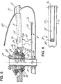
- Fig. 5 a rotor system that has the same basic rotorshaft 18, hub member 28, bearings 32 and 34, flexbeams 14, torqueshafts 24 and other similarly numbered elements as the rotor system of Figs. 1-3.
- hub moment and torque drive are provided by an in-plane compound spring 70, which is shown in isolated top view in Fig. 6.
- the spring 70 is two flat straight springs; an "outward” spring 72 and “inward” spring 74.
- the springs are journaled together at their outboard ends by a joint 76 which is shown in more detail in the top view of Fig. 7 and the end view of Fig. 8.
- the spring 72 has a notch extending most of its length from its outboard end to accommodate the shorter spring 74 between the two "legs" formed thereby in a normally in-plane position.
- the spring 72 is attached at its inboard end at a point radially offset from but in-plane with the tilt point (P), a suitable flange 78 on the rotorshaft.
- the spring 74 is attached at its inboard end at a point radially offset from but in-plane with the tilt point (P), via a suitable spacer 80, to the hub member 28. As the rotor tilts, the spring bends and/or twists to provide a hub moment, in a manner similar to the U-shaped spring 50.
- rotor tilt also causes spring foreshortening.
- the joint 76 is bicentric to allow a lengthwise shift between the spring 72 and the spring 74 and prevent tension or buckling in the spring 70 due to foreshortening.
- the joint 76 includes two outer cuff-like races 82 that attach to the outboard ends of the spring 72 and an outer cuff-like race 84 that attaches to the outboard end of the spring 74.
- the inner race of the joint 76 is a bicentric gudgeon pin 86 having an axis 92 associated with the races 82 and a second, offset axis 94 associated with the race 84. Therefore, as the spring 74 bends relative to the spring 72, it is free to shift longitudinally with respect thereto up to a maximum shift of twice the offset between the axes 92 and 94.
- a "starting position" for the pin must be selected that corresponds to no rotation and no foreshortening of the spring 74. In this case, orienting the axis 94 either directly above or below the axis 92 will provide for appropriate foreshortening.
- Locating the spring 70 in-plane with the tilt point (P) minimizes foreshortening (a radial translation) and also minimizes the azimuthal shift (a tangential translation) between the springs 72 and 74 due to rotor tilt, which is maximum at the tilt axis where there is the most twist.
- the pin 86 is provided with annular shoulders 96 that, in conjunction with the elastomer 88 provide a thrust bearing surface between the race 82 and the races 84 so that torque is driven from the outward legs 72 to the inward legs 74. Also the pin 86 is provided with annular end shoulders 98 to insure interconnecting thrust between the inward and outward springs in conjunction with pin end bolts 99.
- the shoulders 96 and 98 and elastomer 88 also provide a small amount of edgewise damping between the blade and rotorshaft, which may be preloaded by the pin end bolts 99. Elastomer bulge strain is also reduced thereby.
- the spring In the case of either the spring 50 or the spring 70, the spring must be radial to the rotorshaft. As shown in Fig. 2, the blades are prelagged. In other words the pitch axis is offset ahead of a rotorshaft radial. Therefore, the spring is skewed with respect to the arms 31 so that the inward leg of the spring intersects the pitch axis at the point where it attaches to the hub member 28 to equalized the bending and twisting of the springs.
Landscapes
- Engineering & Computer Science (AREA)
- Mechanical Engineering (AREA)
- Aviation & Aerospace Engineering (AREA)
- Pivots And Pivotal Connections (AREA)
- Toys (AREA)
- Springs (AREA)
- Support Of The Bearing (AREA)
Claims (6)
dadurch gekennzeichnet, daß eine erste (32) der sphärischen Lagereinrichtungen (32,34) oberhalb der Nabe (28) und die zweite sphärische Lagereinrichtung (34) unterhalb der Nabe (28) angeordnet ist, beide spharischen Lagereinrichtungen (32,34) die Rotorwelle (18) umgeben und über dem Punkt (P), in welchem die Mittelpunkte zusammenfallen, angeordnet sind.
Applications Claiming Priority (6)
| Application Number | Priority Date | Filing Date | Title |
|---|---|---|---|
| US06/655,386 US4580945A (en) | 1984-09-27 | 1984-09-27 | Helicopter gimbal rotor |
| US655384 | 1984-09-27 | ||
| US06/655,384 US4569629A (en) | 1984-09-27 | 1984-09-27 | Helicopter gimbal rotor |
| US655386 | 1984-09-27 | ||
| US655385 | 1984-09-27 | ||
| US06/655,385 US4566856A (en) | 1984-09-27 | 1984-09-27 | Helicopter gimbal rotor |
Publications (2)
| Publication Number | Publication Date |
|---|---|
| EP0176466A1 EP0176466A1 (de) | 1986-04-02 |
| EP0176466B1 true EP0176466B1 (de) | 1988-07-20 |
Family
ID=27417942
Family Applications (1)
| Application Number | Title | Priority Date | Filing Date |
|---|---|---|---|
| EP19850630156 Expired EP0176466B1 (de) | 1984-09-27 | 1985-09-19 | Hubschrauberrotor mit einem für alle Blätter gemeinsamen Gelenk |
Country Status (2)
| Country | Link |
|---|---|
| EP (1) | EP0176466B1 (de) |
| DE (2) | DE3563833D1 (de) |
Families Citing this family (2)
| Publication number | Priority date | Publication date | Assignee | Title |
|---|---|---|---|---|
| DE3919931A1 (de) * | 1989-06-19 | 1990-12-20 | Messerschmitt Boelkow Blohm | Rotor mit einem schlaggelenkigen blattanschluss im rotorzentrum |
| IT1240177B (it) * | 1990-04-06 | 1993-11-27 | Agusta Spa | Rotore principale per elicotteri |
Family Cites Families (4)
| Publication number | Priority date | Publication date | Assignee | Title |
|---|---|---|---|---|
| FR759185A (fr) * | 1932-10-27 | 1934-01-30 | Brev Et Procedes Bessiere Soc | Perfectionnements aux voilures tournantes |
| US2961051A (en) * | 1955-11-17 | 1960-11-22 | Wilford Edward Burke | Rotor hub and drive system |
| US4232563A (en) * | 1978-03-16 | 1980-11-11 | Barry Wright Corporation | Laminated elastomeric end bearings for articulating links |
| US4323332A (en) * | 1979-12-21 | 1982-04-06 | United Technologies Corporation | Hingeless helicopter rotor with elastic gimbal hub |
-
1985
- 1985-09-19 DE DE8585630156T patent/DE3563833D1/de not_active Expired
- 1985-09-19 DE DE1985630156 patent/DE176466T1/de active Pending
- 1985-09-19 EP EP19850630156 patent/EP0176466B1/de not_active Expired
Also Published As
| Publication number | Publication date |
|---|---|
| DE176466T1 (de) | 1986-09-04 |
| DE3563833D1 (en) | 1988-08-25 |
| EP0176466A1 (de) | 1986-04-02 |
Similar Documents
| Publication | Publication Date | Title |
|---|---|---|
| US4580945A (en) | Helicopter gimbal rotor | |
| US4566856A (en) | Helicopter gimbal rotor | |
| EP1841644B1 (de) | Anordnung zur bereitstellung einer flexur für ein klingensystem | |
| US3967918A (en) | Rotor for rotating wing type aircraft | |
| US9878782B2 (en) | Stiff-in-plane rotor configuration | |
| US4676720A (en) | Bearingless hub structure for rotary-wing aircrafts | |
| US4135856A (en) | Rotor blade retention system | |
| US4569629A (en) | Helicopter gimbal rotor | |
| US3932059A (en) | Droop stops for helicopter rotor having elastomeric bearings | |
| US4714450A (en) | Elastomeric high torque, constant velocity joint | |
| EP2868576A1 (de) | Antriebsverbindung für System mit schwenkbarerm Rotor | |
| US8029371B2 (en) | Rotary-wing aircraft torque coupling with pad bearings | |
| US4575358A (en) | Accommodating axial load in an elastomeric high torque, constant velocity joint | |
| US11040771B2 (en) | Rotor hub | |
| US5007799A (en) | Flapping restrainer device for rotorcraft rotor blades, and rotor head comprising said device | |
| US4708591A (en) | Bladed aircraft rotor with flexible blade mountings | |
| CA2203012A1 (en) | Snubber bearing mounting assembly for bearingless rotors | |
| US11691723B2 (en) | Rotor assembly with static mast and pivoting rotor hub | |
| EP0176466B1 (de) | Hubschrauberrotor mit einem für alle Blätter gemeinsamen Gelenk | |
| EP1228961B1 (de) | Getriebeanordnung für einen Flugzeugrotor mit konstanter Geschwindigkeit | |
| US20030235499A1 (en) | Multi focus hemi-spherical elastic bearing | |
| US4676669A (en) | Tailoring tilt in an elastomeric high torque, constant velocity joint | |
| US4759689A (en) | Bladed aircraft rotor with flexible blade mountings | |
| JPH057240B2 (de) | ||
| EP0491647B1 (de) | Dämpfer-Lager mit zusammengestellten Elastomerschichten |
Legal Events
| Date | Code | Title | Description |
|---|---|---|---|
| PUAI | Public reference made under article 153(3) epc to a published international application that has entered the european phase |
Free format text: ORIGINAL CODE: 0009012 |
|
| AK | Designated contracting states |
Kind code of ref document: A1 Designated state(s): DE FR GB IT |
|
| 17P | Request for examination filed |
Effective date: 19860521 |
|
| ITCL | It: translation for ep claims filed |
Representative=s name: RICCARDI SERGIO & CO. |
|
| EL | Fr: translation of claims filed | ||
| DET | De: translation of patent claims | ||
| 17Q | First examination report despatched |
Effective date: 19870108 |
|
| GRAA | (expected) grant |
Free format text: ORIGINAL CODE: 0009210 |
|
| AK | Designated contracting states |
Kind code of ref document: B1 Designated state(s): DE FR GB IT |
|
| REF | Corresponds to: |
Ref document number: 3563833 Country of ref document: DE Date of ref document: 19880825 |
|
| ET | Fr: translation filed | ||
| ITF | It: translation for a ep patent filed |
Owner name: UFFICIO BREVETTI RICCARDI & C. |
|
| PLBE | No opposition filed within time limit |
Free format text: ORIGINAL CODE: 0009261 |
|
| STAA | Information on the status of an ep patent application or granted ep patent |
Free format text: STATUS: NO OPPOSITION FILED WITHIN TIME LIMIT |
|
| 26N | No opposition filed | ||
| ITTA | It: last paid annual fee | ||
| PGFP | Annual fee paid to national office [announced via postgrant information from national office to epo] |
Ref country code: FR Payment date: 19950803 Year of fee payment: 11 |
|
| PGFP | Annual fee paid to national office [announced via postgrant information from national office to epo] |
Ref country code: GB Payment date: 19950815 Year of fee payment: 11 |
|
| PGFP | Annual fee paid to national office [announced via postgrant information from national office to epo] |
Ref country code: DE Payment date: 19950823 Year of fee payment: 11 |
|
| PG25 | Lapsed in a contracting state [announced via postgrant information from national office to epo] |
Ref country code: GB Effective date: 19960919 |
|
| PG25 | Lapsed in a contracting state [announced via postgrant information from national office to epo] |
Ref country code: FR Effective date: 19960930 |
|
| GBPC | Gb: european patent ceased through non-payment of renewal fee |
Effective date: 19960919 |
|
| PG25 | Lapsed in a contracting state [announced via postgrant information from national office to epo] |
Ref country code: DE Effective date: 19970603 |
|
| REG | Reference to a national code |
Ref country code: FR Ref legal event code: ST |
|
| REG | Reference to a national code |
Ref country code: FR Ref legal event code: ST |