EP0175657A1 - An interface device among one or more computers and sensors and actuators in control apparatuses - Google Patents
An interface device among one or more computers and sensors and actuators in control apparatuses Download PDFInfo
- Publication number
- EP0175657A1 EP0175657A1 EP85830229A EP85830229A EP0175657A1 EP 0175657 A1 EP0175657 A1 EP 0175657A1 EP 85830229 A EP85830229 A EP 85830229A EP 85830229 A EP85830229 A EP 85830229A EP 0175657 A1 EP0175657 A1 EP 0175657A1
- Authority
- EP
- European Patent Office
- Prior art keywords
- sensors
- interface device
- computers
- interface
- serial
- Prior art date
- Legal status (The legal status is an assumption and is not a legal conclusion. Google has not performed a legal analysis and makes no representation as to the accuracy of the status listed.)
- Withdrawn
Links
Images


Classifications
-
- G—PHYSICS
- G05—CONTROLLING; REGULATING
- G05B—CONTROL OR REGULATING SYSTEMS IN GENERAL; FUNCTIONAL ELEMENTS OF SUCH SYSTEMS; MONITORING OR TESTING ARRANGEMENTS FOR SUCH SYSTEMS OR ELEMENTS
- G05B19/00—Programme-control systems
- G05B19/02—Programme-control systems electric
- G05B19/04—Programme control other than numerical control, i.e. in sequence controllers or logic controllers
- G05B19/042—Programme control other than numerical control, i.e. in sequence controllers or logic controllers using digital processors
- G05B19/0423—Input/output
Landscapes
- Physics & Mathematics (AREA)
- General Physics & Mathematics (AREA)
- Engineering & Computer Science (AREA)
- Automation & Control Theory (AREA)
- Alarm Systems (AREA)
- Control By Computers (AREA)
- Programmable Controllers (AREA)
Abstract
The object of this invention is an interface device (1) for control apparatuses formed by sensors (44) of the antitheft type, applied, for instance, in different places which are to be watched as doors, windows and the like, or of another type such as anti-fire, anti-flooding and the like, and one or more computers (10A) (10B) which receive the information from said sensors, elaborate said information according to predetermined programs loaded into said computers, and then send to the interface (1) the necessary instructions for activating the actuators (45) of the physical operations of the control. Said device (1) includes an intelligent unit formed by a central processing unit (2) having permanent and volatile memories (3) and parallel/serial conversion circuits (8) for serial communication with the computer (10A) and with possible accessory management devices (9), parallel input/ output circuits (4) (5) (6) (7), in combination with an interface unit in which the number of the contacts for the control functions and the number of the digital optoisolated inputs for the logic states of the sensors may be selected according to the special purposes required.
Description
- The present invention relates to a device which is effective to act as an interface between one or more computers and a series of sensors and contacts for detecting the state of the sensors therein, and activating or deactivating appropriate contacts connected to apparatuses which are pre-arranged for intervention, alarm and the like, according to special programs.
- In various systems, in which detecting of events with subsequent intervention of organs, apparatuses and the like is required, depending on the event which occurred, having to be detected by said systems, it arises the problem of establishing the combination between the causes represented by the state of said sensors and the effects represented by the activation of the control contacts of said organs or apparatuses.
- On the other side, it also arises the necessity of being independent from a rigidly predetermined situation, in order to have the possibility, also for the user, of easily varying the combinations which control the actuations.
- Above technical problem has been solved, in accordance with the present invention, by providing an interface device to be connected at one end with one or more computers and at the other end with sensors and actuating contacts, and being suitable to allow the automatic bidirectional transmission of information and commands among the sensors and the computers and among the computers and the actuators.
- Said interface device is not provided with an intelligence of its own, and cannot therefore decide the combination of the actions to undertake, but it can detect the state of the sensors and transmit it to the computer; from this latter it receives commands for activating the contacts and execute them. The management of the control functions, according to the present invention, is provided to be effected by the programs loaded on the computers, which are connected to the interface device.
- Therefore, this invention presents the advantage of offering the possibility, also to the user, of changing the combinations of actions very quickly, thereby disengaging the control management from the fixed correspondence between the operation of detecting the state of the sensors and the subsequent activation of the contacts, which according to the prior art would be determined by utilizing a static circuit.
- The mentioned technical problems are solved by means of an interface device, applied among one or more computers and sensors and actuators in a control apparatus and the like, comprising:
- an intelligent unit constituted by a central processing unit and permanent memories, which are connected to said central processing unit, for recording the instructions of the dialogue with said computers and of sampling the sensors; volatile memories connected to said central processing unit for recording temporary data; programmable serial processors for the connnection with said computers and/or reading, recording or similar devices; programmable integrated circuits generating the serial communication frequencies and the internal clocks, at least one parallel input/output device for pre-driving the control circuits of the contacts or relays acting on said actuators, which operate the system control functions; an input unit which receives the signals coming from the sensors and identifies the provenance sensor; a power supply unit comprising voltage regulators, suitable to supply a controlled voltage to the different electronic devices of the interface , completes the general diagram of the invention.
- In particular, said intelligent unit is constituted by a microprocessor, preferably having eight or more bits, and by one or more integrated circuits of the EPROM type connected to said microprocessor, while the volatile memories are formed by integrated circuits of the RAM type, in connection with said microprocessor of said intelligent unit.
- Said programmable serial processors comprise:
- a programmable integrated circuit, which is suitable to generate serial communication frequencies and internal clocks, a frequency divider, an integrated serial processor, a circuit capable of determinating the. enabling priority between said frequencies generator and said integrated serial processor, and devices for communicating with the peripheral organs.
- Said devices for communicating with the peripheral organs consist of at least four level translators depending upon the number of the provided outputs.
- Conveniently, the peripheral organs include at least one computer and, possibly, at least one reading or recording or similar device, preferably embodied by a reader for magnetic cards, for example, of the personal identity card type, known with the english name "badge" for application in intrusion-detecting systems.
- Said input unit includes an optoisolator for each input, a decoder and a logic circuit, preferably of the exclusive OR type, determinating the direction of the communications.
- A further characteristic of the interface device according to the present invention is the possibility for the user of fixing the number of the sensors enabled to send the signals, by means of the programs of said one or more computers.
- The above and other objects, features and advantages of the present invention will become more readily apparent from the following description, reference being made to the accompanying drawing, in which:
- Fig. 1 is a blocks diagram generally and schematically illustrating an embodiment of the interface device.
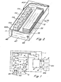
- Fig. 2 is a perspective view of the interface device according to the invention.
- Fig. 3 is a simplified circuit diagram of the central processing unit.
- Fig. 4 is a simplified circuit diagram of the printed circuit board embodying the programmable serial processor.
- Fig. 5 is a simplified circuit diagram of the intercommunication circuits with the sensors through the optoisolator.
- Fig. 6 is a preferred embodiment of a driving stage of the relays.
- The electrical interconnections, not shown, are executed in a known manner, by connecting for each element the corresponding circuit elements, utilizing alpha-numerical symbols, which are indicated in the elements themselves.
- As is apparent from fig. 1, the interface device, generally indicated 1, is provided with a central processing unit 2 (known as CPU), a
data memory 3, asensor decoder 4 and anoptoisolator group 5, located along the bus a between sensors and CPU; moreover, a series ofenergy level translators 6 and a series ofrelays 7 placed on the bus b between CPU and the ON-OFF type actuators for actuating different devices are provided. - Said
interface device 1 also comprises a programmableserial processor 8, provided with bus, generally indicated c, which may be connected to recognizing devices, for instance, of the electromagnetic card type, indicated by thereference 9, and a bus d, with one or more, preferably two computers, indicated in fig. 1 10A and 10B; apower supply unit 11 for the various elements is also provided; in this figure, ageneric sensor 44 and ageneric actuator 45, among the many types which may be provided, are represented. - As shown in fig. 2, the
power supply unit 11 comprises a series of known elements indicated 11A, 11B, 11C, 11D (transformers, capacitors, voltage regulators and the like), these elements having in input a line voltage, being effective to supply the necessary voltage levels for the controlled feeding of the digital circuital part and of the optoisolator part, more particularly: 5 Volts for the TTL logic circuits, which will be described hereinafter, 12 Volts for said programmableserial processors 8 and a further 12 Volts voltage, differing from the foregoing voltage because of the complete decoupling between voltage and ground, which is utilized for feeding theoptoisolator group 5. - Referring now in particular to fig. 2 and fig. 5, it will be described a representative but not limitative embodiment of the electrical circuit and of the components of the
central processing unit 2, being formed by a printedcircuit board 12, on which the necessary logic micro- components are located; in particular: a microprocessor 13 (a known type with tradename Z80) having known regulating components, which are therefore not to be described; five integrated circuits, one of which being anEPROM 14 type memory and the others, indicated 15A, 15B, 15C, 15D, being RAM type memories; twodecoder elements electrical configurations central processing unit 2; aknown crystal oscillator 18 which supplies the operative frequency of the intelligent integrated circuits and an initializinggroup 19 for the hand-reset of the system during testing. The diagram is completed by a connecting element among the boards, consisting of twointercommunication units (known as transceiver) 20 and 21, saidtransceiver 21 being enabled by a logical circuit AND 22, and the communication direction beings determined by an exclusive ORlogic circuit 24. Adecoder 23 for the signals coming from theintercommunication circuits intelligent chips CPU 12 board there is located the printedcircuits board 25 forming the programmable serial processor; on said board there is provided a programmableelectronic component 26, generating the serial communication frequencies, and the internal clocks; furthermore, there is provided afrequency divider 27, acircuit 27A determinating priority between saidcircuit 26 and theserial processor 28, as well as theenergy level translators output device 30 for pre-driving the relays control circuits and by thelogic elements 31A and 31B, coupled with thedecoder 23. - A further element constituting this system is the printed
circuits board 30, comprising fourintercommunication circuits points optoisolator 37. Saidblock 37 being provided on each sensor and consisting of anoptoisolator 38 of the prior art, two resistances R39 and R40, which are effective for the correct limitation of the circulating current, and aninput 41 for connection to the sensor. - In fig. 6, the
driving stage 36 of arelay 34 is illustrated, the output of which becoming outwardly available, by means of, a connector, not shown in said figure. The input of thedriving stage 36 is received by theblock 30 through theconnector 42; the device being completed by aprotective diode 35. - The above described circuit components are located in a substantially
rectangular container 43 formed by twoparts - The flow of the signals, going from the sensors to the interface, therefrom to the computer and back, is as follows:
- the
generic sensor 44 determinates, by means of its open or closed state, a logic voltage level in the output from theoptoisolator 5, which eliminates the passage of possible noise to the circuitry; said voltage passes through thetransceiver 21 to themicroprocessor 13; the CPU effects a preliminary filtering through a program to eliminate eventual electric transients, which may be identified as useful signals and it successively records on the available RAM memories the signal indicating the state of the sensor. - The
computer 10A sends a cyclic inquiry about the sensor state, via the programmableserial processor 8, and the interface replies sending an answer when no sensor varied its state, or sending the code of the sensor, or sensors, which have changed their actual state. Via the same bus, the signals can reach the computer which, in turn, compares them by means of the program with the signals previously loaded into its memory. - In case of variation in the sensor state, the computer searches in its memory the instructions related to the operations which are to be effected with respect to such particular detected variation; otherwise, when no variation in the actual state of the sensors occurred, the computer goes on sending its inquiry about the state of the sensors. At this point, the flow of the instructions is starting and, from the
computer 10A, will reach the generic actuator indicated 45, as fixed by the program. - More particularly, said signal arrives, via the programmable
serial processor 8, to thecentral processing unit 2 which, after effecting a control of congruence through program, sends to theenergy level translator 6, constituted by theintegrated circuit 36, a precise signal or voltage level, which is apt to excite the corresponding relay, while this relay, connected to an actuator device of whatever type (electrical sirens, water-streams or the like), will enable the operation which is provided for to be effected. - Fig. 2 illustrates also the
frontal panel 47 of said device, on which panel there are incorporated thewarning lights 48, signalling the state of the device, and a knowntype keylock switch 49 for starting the system. - Many variations may be introduced in the practical execution of embodiments according to the present invention, without, however, moving away from the general context of the invention and its global characteristics.
Claims (8)
1) An interface device among one or more computers and sensors and actuators in control apparatuses or the like characterised in that it comprises in combination: at least a central processing unit having permanent memories connected to said central processing unit for recording the instructions for the dialogue with sail computers and of sampling of the sensors, volatile memories connected to said central processing unit for recording temporary data; programmable serial processors for the connection with the computers and/or reading, recording or similar devices, programmable integrated circuits generating the serial communication frequencies and the internal clocks; at least one parallel input/output device for pre-driving the control circuits of the contacts or relays acting on said actuators which operate the system control functions, an input unit which receives the signals coming from the sensors and identifies the sensor itself, a power supply unit comprising voltage regulators which are suitable to supply a controlled voltage to the different electronic devices of the interface.
2) An interface device according to claim 1 characterised in that said intelligent unit is constituted by a microprocessor, preferably having eight or more bits, and by one or more integrated circuits of the EPROM type connected to said microprocessor, constituting the permanent memory.
3) An interface device according to claim 1 characterised in that said volatile memories are formed by integrated circuits of the RAM type in connection with said microprocessor of said intelligent unit.
4) An interface device according to claim 1 characterised in that said programmable serial processors comprise: a programmable integrated circuit which is suitable to generate serial communication frequencies and internal clocks; a frequency divider; an integrated serial processor; a circuit capable of determinating the enabling priority between said frequencies generator and said integrated serial processor; devices for communicating with the peripheral organs.
5) An interface device according to the preceding claims characterised in that said devices for communicating with the peripheral organs consist of at least four level translators depending upon the number of the outputs provided.
6) An interface device according to the preceding claims characterised in that said peripheral organs include at least one computer and, possibly, a reading, recording or similar device, preferably embodied by a reader for magnetic cards.
7) An interface device according to the preceding claims characterised in that said input unit includes an optoisolator for each input, a decoder and a logic circuit, conveniently of the exclusive OR type, determinating the direction of the communication.
8) An interface device according to the preceding claims characterised in that the number of the sensors enabled to send the signals may be fixed from the user by means of the programs of said one or more computers.
Applications Claiming Priority (2)
| Application Number | Priority Date | Filing Date | Title |
|---|---|---|---|
| IT22666/84A IT1175735B (en) | 1984-09-14 | 1984-09-14 | INTERFACE DEVICE BETWEEN CALCULATORS AND SENSORS, ACTUATORS IN CONTROL SYSTEMS |
| IT2266684 | 1984-09-14 |
Publications (1)
| Publication Number | Publication Date |
|---|---|
| EP0175657A1 true EP0175657A1 (en) | 1986-03-26 |
Family
ID=11199034
Family Applications (1)
| Application Number | Title | Priority Date | Filing Date |
|---|---|---|---|
| EP85830229A Withdrawn EP0175657A1 (en) | 1984-09-14 | 1985-09-12 | An interface device among one or more computers and sensors and actuators in control apparatuses |
Country Status (4)
| Country | Link |
|---|---|
| EP (1) | EP0175657A1 (en) |
| JP (1) | JPS61112205A (en) |
| ES (1) | ES8700769A1 (en) |
| IT (1) | IT1175735B (en) |
Cited By (3)
| Publication number | Priority date | Publication date | Assignee | Title |
|---|---|---|---|---|
| EP0568420A1 (en) * | 1992-04-30 | 1993-11-03 | STMicroelectronics S.A. | Programmable interface, especially for control of domestic appliances |
| US5764948A (en) * | 1993-04-29 | 1998-06-09 | Sgs-Thomson Microelectronics S.A. | Method and apparatus for determining a composition of an integrated circuit |
| AT5042U3 (en) * | 2001-10-08 | 2002-10-25 | Avl List Gmbh | MEASURING DEVICE |
Citations (5)
| Publication number | Priority date | Publication date | Assignee | Title |
|---|---|---|---|---|
| EP0021232A1 (en) * | 1979-06-12 | 1981-01-07 | Fritz Fuss Kom.-Ges. | Device for a burglary alarm system |
| US4263655A (en) * | 1979-07-26 | 1981-04-21 | The United States Of America As Represented By The Secretary Of The Army | Digital interface circuit for control of pressure scanner |
| US4410961A (en) * | 1981-02-17 | 1983-10-18 | Pitney Bowes Inc. | Interface between a processor system and peripheral devices used in a mailing system |
| EP0106191A1 (en) * | 1982-09-22 | 1984-04-25 | Siemens Aktiengesellschaft | Multiprocessor system for a danger alarm installation |
| DE3415008A1 (en) * | 1983-04-27 | 1984-10-31 | Siemens AG, 1000 Berlin und 8000 München | System arrangement for electric signal transmission and signal processing |
-
1984
- 1984-09-14 IT IT22666/84A patent/IT1175735B/en active
-
1985
- 1985-09-12 EP EP85830229A patent/EP0175657A1/en not_active Withdrawn
- 1985-09-13 ES ES546930A patent/ES8700769A1/en not_active Expired
- 1985-09-14 JP JP60204165A patent/JPS61112205A/en active Pending
Patent Citations (5)
| Publication number | Priority date | Publication date | Assignee | Title |
|---|---|---|---|---|
| EP0021232A1 (en) * | 1979-06-12 | 1981-01-07 | Fritz Fuss Kom.-Ges. | Device for a burglary alarm system |
| US4263655A (en) * | 1979-07-26 | 1981-04-21 | The United States Of America As Represented By The Secretary Of The Army | Digital interface circuit for control of pressure scanner |
| US4410961A (en) * | 1981-02-17 | 1983-10-18 | Pitney Bowes Inc. | Interface between a processor system and peripheral devices used in a mailing system |
| EP0106191A1 (en) * | 1982-09-22 | 1984-04-25 | Siemens Aktiengesellschaft | Multiprocessor system for a danger alarm installation |
| DE3415008A1 (en) * | 1983-04-27 | 1984-10-31 | Siemens AG, 1000 Berlin und 8000 München | System arrangement for electric signal transmission and signal processing |
Cited By (5)
| Publication number | Priority date | Publication date | Assignee | Title |
|---|---|---|---|---|
| EP0568420A1 (en) * | 1992-04-30 | 1993-11-03 | STMicroelectronics S.A. | Programmable interface, especially for control of domestic appliances |
| FR2690766A1 (en) * | 1992-04-30 | 1993-11-05 | Sgs Thomson Microelectronics | Programmable interface especially for the control of domestic installations. |
| US5537651A (en) * | 1992-04-30 | 1996-07-16 | Sgs-Thomson Microelectronics S.A. | Programmable interface, notably for the control of domestic installations |
| US5764948A (en) * | 1993-04-29 | 1998-06-09 | Sgs-Thomson Microelectronics S.A. | Method and apparatus for determining a composition of an integrated circuit |
| AT5042U3 (en) * | 2001-10-08 | 2002-10-25 | Avl List Gmbh | MEASURING DEVICE |
Also Published As
| Publication number | Publication date |
|---|---|
| JPS61112205A (en) | 1986-05-30 |
| IT8422666A0 (en) | 1984-09-14 |
| ES546930A0 (en) | 1986-11-16 |
| IT1175735B (en) | 1987-07-15 |
| ES8700769A1 (en) | 1986-11-16 |
Similar Documents
| Publication | Publication Date | Title |
|---|---|---|
| US4524288A (en) | System for power supply to and switching of a number of electrical appliances | |
| US4504927A (en) | Programmable controller with expandable I/O interface circuitry | |
| US7941567B2 (en) | Modular computer system and I/O module | |
| US4528459A (en) | Battery backup power switch | |
| EP0277302A1 (en) | Smart control and sensor devices single wire bus multiplex system | |
| EP0426663A1 (en) | Apparatus for defined switching of a microcomputer to standby mode. | |
| DE19742845A1 (en) | Wired / wireless keyboard and control methods therefor | |
| FR2581220B1 (en) | SYSTEM AND METHOD FOR PROVIDING REPROGRAMMING DATA TO A SPECIALIZED PROCESSOR OF THE EQUIPMENT INTEGRATED TYPE | |
| KR920004643A (en) | Operation control device of washing machine | |
| EP0175657A1 (en) | An interface device among one or more computers and sensors and actuators in control apparatuses | |
| EP0325884B1 (en) | Keyboard arrangement with ghost key condition detection | |
| US4720810A (en) | Electronic control arrangement for controlling a plurality of outputs in accordance with the electrical state of a plurality of inputs | |
| KR900006286B1 (en) | Process input/output system | |
| GB1589444A (en) | Electrical communication system | |
| US4959831A (en) | Single wire bus smart keypad controller system | |
| US7107379B2 (en) | Method for connecting an expansion module to a programmable electric switching device | |
| US6727721B2 (en) | Method for switching from a first operating condition of an integrated circuit to a second operating condition of the integrated circuit | |
| US6308230B1 (en) | Information/software interface having serial communications detection logic/electronics for determining either a host or an embedded microcomputer device controller connected thereto | |
| FR2786901B1 (en) | DEVICE AND METHOD FOR INITIALIZING AN APPLICATION PROGRAM OF AN INTEGRATED CIRCUIT CARD | |
| EP0907137A1 (en) | IC card processing system and processing method | |
| US2795476A (en) | Keyboard-controlled programming and imprinting apparatus, method of entering data and novel record format | |
| JPS6132157A (en) | Characteristic deciding system of process input and output device | |
| ES8308649A1 (en) | Method and circuit arrangement to optimize the operation of an electronic taximeter. | |
| US5504671A (en) | Radio system combiner filter control system wherein plural auxiliary cards automatically obtain correct address from motherboard upon being inserted in respective auxiliary card connectors | |
| KR200299029Y1 (en) | Access control system |
Legal Events
| Date | Code | Title | Description |
|---|---|---|---|
| PUAI | Public reference made under article 153(3) epc to a published international application that has entered the european phase |
Free format text: ORIGINAL CODE: 0009012 |
|
| AK | Designated contracting states |
Kind code of ref document: A1 Designated state(s): AT BE CH DE FR GB LI LU NL SE |
|
| STAA | Information on the status of an ep patent application or granted ep patent |
Free format text: STATUS: THE APPLICATION IS DEEMED TO BE WITHDRAWN |
|
| 18D | Application deemed to be withdrawn |
Effective date: 19861127 |
|
| RIN1 | Information on inventor provided before grant (corrected) |
Inventor name: CARBONERA, ANTONIO |