EP0175502A2 - A discharge tube for a high pressure metal vapour discharge lamp and a method of manufacturing the same - Google Patents
A discharge tube for a high pressure metal vapour discharge lamp and a method of manufacturing the same Download PDFInfo
- Publication number
- EP0175502A2 EP0175502A2 EP85306012A EP85306012A EP0175502A2 EP 0175502 A2 EP0175502 A2 EP 0175502A2 EP 85306012 A EP85306012 A EP 85306012A EP 85306012 A EP85306012 A EP 85306012A EP 0175502 A2 EP0175502 A2 EP 0175502A2
- Authority
- EP
- European Patent Office
- Prior art keywords
- tubular body
- end plate
- discharge tube
- bonded
- high pressure
- Prior art date
- Legal status (The legal status is an assumption and is not a legal conclusion. Google has not performed a legal analysis and makes no representation as to the accuracy of the status listed.)
- Granted
Links
Images

Classifications
-
- H—ELECTRICITY
- H01—ELECTRIC ELEMENTS
- H01J—ELECTRIC DISCHARGE TUBES OR DISCHARGE LAMPS
- H01J61/00—Gas-discharge or vapour-discharge lamps
- H01J61/02—Details
- H01J61/36—Seals between parts of vessels; Seals for leading-in conductors; Leading-in conductors
- H01J61/361—Seals between parts of vessel
- H01J61/363—End-disc seals or plug seals
-
- H—ELECTRICITY
- H01—ELECTRIC ELEMENTS
- H01J—ELECTRIC DISCHARGE TUBES OR DISCHARGE LAMPS
- H01J9/00—Apparatus or processes specially adapted for the manufacture, installation, removal, maintenance of electric discharge tubes, discharge lamps, or parts thereof; Recovery of material from discharge tubes or lamps
- H01J9/24—Manufacture or joining of vessels, leading-in conductors or bases
- H01J9/26—Sealing together parts of vessels
- H01J9/265—Sealing together parts of vessels specially adapted for gas-discharge tubes or lamps
- H01J9/266—Sealing together parts of vessels specially adapted for gas-discharge tubes or lamps specially adapted for gas-discharge lamps
Definitions
- the present invention relates to a discharge tube for a high pressure metal vapour lamp, e.g. a metal halide discharge lamp, and a method for manufacturing the tube.
- a high pressure metal vapour lamp e.g. a metal halide discharge lamp
- a translucent alumina which withstands corrosive metal halides is used for a tubular body of a discharge tube of a high pressure metal vapour discharge lamp, particularly the metal halide lamp in which the metal halide is sealed, and alumina or cermet is used as end plates comprising electrode support members at the ends of the tubular body.
- a frit see, for instance, US Patent 3,885,184 and 4,001,625
- the present invention aims to reduce or avoid the above drawbacks of the prior art, and to provide a discharge tube for a high pressure metal vapour discharge lamp which can have a high discharge efficiency and a long durable life.
- a discharge tube for a high pressure metal vapour discharge lamp which discharge tube comprises a translucent alumina tubular body, a lower end plate bonded to one end portion of the alumina tubular body which has an electrode support member inside thereof and is bonded to the alumina tubular body when the alumina tube is subjected to the light transmission treatment through firing, another end plate which has an electrode support member inside thereof and is bonded to the other end of the translucent alumina tubular body by means of a frit.
- a method of manufacturing a discharge tube for a high pressure metal vapour discharge lamp comprises steps of inserting an end plate in which an electrode support member is partially embedded on the inner side thereof into one end portion of a tubular body made of high purity alumina, and firing the green or calcined tubular body with the end plate, whereby the tubular body is made translucent and simultaneously the end plate is bonded to the tubular body.
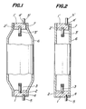
- the discharge tube for a high pressure metal vapour discharge lamp shown has an end plate l, and a recess 2 formed on the inner side of the end plate 1 into which an electrode support member 3 is fitted.
- the end plate 1 is bonded to a tubular body 6 at the lower end thereof while the tubular body 6 is rendered translucent by firing.
- An electric current conducting member 5 is fitted into a recess 4 formed in the end plate 1 at the outer side thereof.
- An end plate 1' of the same or similar shape as the end plate 1 carries an electrode support member 3' and an electric current conducting member 5'. This end plate is attached to the upper end portion of the discharge tubular body 6 by means of a frit 7.
- the end plate 1 is formed from a material of excellent electric conductivity such as alumina-tungsten, alumina-molybdenum tungsten boride. Then the electrode support member 3 made of tungsten is inserted into the recess 2 provided on the inner side of the end plate 1 and the electric current conductor 5 is inserted into the recess 4 on the outer side of the end plate 1. Thereafter, the electrode support member 3 and the electric current conductor 5 are bonded to the end plate 1 through firing. Before this, the green tubular body 6 is formed from high purity alumina, and is calcined in air.
- the above end plate 1 is fitted into one end of the calcined tubular body 6, and the whole tubular body with the end plate 1 is fired at a high temperature of around 1,900°C with hydrogen gas in a reducing atmosphere electric furnace to render the tubular body 6 translucent and at the same time firmly bond the end plate 1 to the tubular body 6. Since the firing shrinkage factor of the cermet constituting the end plate 1 is smaller than that of the high purity alumina constituting the tubular body 6, this bonding is carried out in the state of shrinkage fitting, while a gas tight bonding is achieved by sintering between the end plate and the high purity alumina.
- a metal halide is then put into the tubular body 6 to which the end plate is directly bonded at the lower end threof without use of frit.
- the sealed-in substance may change into liquid, so that the chemical reactivity at the inner surface of the lower end portion increases.
- the end plate 1' equipped with the electrode support member 3' and the electric current conductor 5', which end plate is preliminarily formed in the same way as mentioned above, is bonded to the upper end surface of the tubular body 6 by means of a glass frit 7.
- the profile of the tubular body 6 may be a cylindrical tubular form as shown in Fig. 2 instead of that shown in Fig. 1.
- the electric current conductors 5, 5' of the high pressure metal vapour discharge lamp thus produced are connected to an electric power source (not shown), electric current flows to the electrode support members 3 and 3' through the electric conductive end plates 1 and 1' to effect the discharge.
- the sealed-in substance is changed to liquid, but the bonded portion is not corroded by the liquid of high reactivity because the end plate 1 and the tubular body 6 are directly bonded through sintering without use of the frit at the lower end of the tubular body. Therefore, the discharge tube can be used at a temperature higher than the temperature of use of the conventional discharge tube of the metal halide discharge lamp, and a higher discharge efficiency can be obtained, while a long life can be attained.
- the electrode support members 3 and 3' may suitably pass through the end plates 1 and 1' to project outwardly.
- the other features of the embodiment shown in Fig. 3 are the same as or similar to those shown in Figs. 1 and 2. Detailed explanation of the embodiment of Fig. 3 is therefore omitted.
Landscapes
- Engineering & Computer Science (AREA)
- Manufacturing & Machinery (AREA)
- Vessels And Coating Films For Discharge Lamps (AREA)
- Manufacture Of Electron Tubes, Discharge Lamp Vessels, Lead-In Wires, And The Like (AREA)
Abstract
Description
- The present invention relates to a discharge tube for a high pressure metal vapour lamp, e.g. a metal halide discharge lamp, and a method for manufacturing the tube.
- A translucent alumina which withstands corrosive metal halides is used for a tubular body of a discharge tube of a high pressure metal vapour discharge lamp, particularly the metal halide lamp in which the metal halide is sealed, and alumina or cermet is used as end plates comprising electrode support members at the ends of the tubular body. When the discharge tube.is produced by assembling these parts together, it is a common practice to bond the end plates by means of a frit (see, for instance, US Patent 3,885,184 and 4,001,625) to the opposite ends of the tubular alumina body which has been made translucent through preliminary firing.
- However, the temperature of use of the discharge tube produced by such a method cannot be sufficiently raised since there is a fear that the frit will be corroded with the metal halide. Consequently the discharge efficiency must unfavourably be suppressed to a level far lower than the theoretical value. In addition even a relatively short durable life cannot be attained. Therefore, a method which allows easy production of a discharge tube for a metal halide lamp which is high in discharge efficiency and has a long durable life has been sought.
- The present invention aims to reduce or avoid the above drawbacks of the prior art, and to provide a discharge tube for a high pressure metal vapour discharge lamp which can have a high discharge efficiency and a long durable life.
- According to the first aspect of the present invention, there is provided a discharge tube for a high pressure metal vapour discharge lamp, which discharge tube comprises a translucent alumina tubular body, a lower end plate bonded to one end portion of the alumina tubular body which has an electrode support member inside thereof and is bonded to the alumina tubular body when the alumina tube is subjected to the light transmission treatment through firing, another end plate which has an electrode support member inside thereof and is bonded to the other end of the translucent alumina tubular body by means of a frit.
- According to a second aspect of the present invention, there is provided a method of manufacturing a discharge tube for a high pressure metal vapour discharge lamp, which method comprises steps of inserting an end plate in which an electrode support member is partially embedded on the inner side thereof into one end portion of a tubular body made of high purity alumina, and firing the green or calcined tubular body with the end plate, whereby the tubular body is made translucent and simultaneously the end plate is bonded to the tubular body.
- Embodiments of the invention will now be described by way of example with reference to the accompanying drawings, wherein:
- Fig. 1 is a partially cutaway front view of an embodiment of a discharge tube for a high pressure metal vapour discharge lamp according to the present invention; and
- Figs. 2 and 3 are other embodiments of a discharge tube for a high pressure metal vapour discharge lamp according to the present invention.
- Throughout this description and the drawings, identical reference numerals denote the same or similar parts.
- In Fig. 1, the discharge tube for a high pressure metal vapour discharge lamp shown has an end plate l, and a
recess 2 formed on the inner side of the end plate 1 into which anelectrode support member 3 is fitted. The end plate 1 is bonded to atubular body 6 at the lower end thereof while thetubular body 6 is rendered translucent by firing. An electriccurrent conducting member 5 is fitted into arecess 4 formed in the end plate 1 at the outer side thereof. An end plate 1' of the same or similar shape as the end plate 1 carries an electrode support member 3' and an electric current conducting member 5'. This end plate is attached to the upper end portion of the dischargetubular body 6 by means of a frit 7. - Next, a method of manufacturing this discharge tube will be described in detail.
- First, the end plate 1 is formed from a material of excellent electric conductivity such as alumina-tungsten, alumina-molybdenum tungsten boride. Then the
electrode support member 3 made of tungsten is inserted into therecess 2 provided on the inner side of the end plate 1 and the electriccurrent conductor 5 is inserted into therecess 4 on the outer side of the end plate 1. Thereafter, theelectrode support member 3 and the electriccurrent conductor 5 are bonded to the end plate 1 through firing. Before this, the greentubular body 6 is formed from high purity alumina, and is calcined in air. The above end plate 1 is fitted into one end of the calcinedtubular body 6, and the whole tubular body with the end plate 1 is fired at a high temperature of around 1,900°C with hydrogen gas in a reducing atmosphere electric furnace to render thetubular body 6 translucent and at the same time firmly bond the end plate 1 to thetubular body 6. Since the firing shrinkage factor of the cermet constituting the end plate 1 is smaller than that of the high purity alumina constituting thetubular body 6, this bonding is carried out in the state of shrinkage fitting, while a gas tight bonding is achieved by sintering between the end plate and the high purity alumina. - A metal halide is then put into the
tubular body 6 to which the end plate is directly bonded at the lower end threof without use of frit. When the lamp is in operation, the sealed-in substance may change into liquid, so that the chemical reactivity at the inner surface of the lower end portion increases. Finally, the end plate 1' equipped with the electrode support member 3' and the electric current conductor 5', which end plate is preliminarily formed in the same way as mentioned above, is bonded to the upper end surface of thetubular body 6 by means of a glass frit 7. The profile of thetubular body 6 may be a cylindrical tubular form as shown in Fig. 2 instead of that shown in Fig. 1. - When the
electric current conductors 5, 5' of the high pressure metal vapour discharge lamp thus produced are connected to an electric power source (not shown), electric current flows to the electrode supportmembers 3 and 3' through the electric conductive end plates 1 and 1' to effect the discharge. At that time, the sealed-in substance is changed to liquid, but the bonded portion is not corroded by the liquid of high reactivity because the end plate 1 and thetubular body 6 are directly bonded through sintering without use of the frit at the lower end of the tubular body. Therefore, the discharge tube can be used at a temperature higher than the temperature of use of the conventional discharge tube of the metal halide discharge lamp, and a higher discharge efficiency can be obtained, while a long life can be attained. - When the end plates 1 and 1' are made of a nonconductive material, as shown in Fig. 3, the electrode support
members 3 and 3' may suitably pass through the end plates 1 and 1' to project outwardly. The other features of the embodiment shown in Fig. 3 are the same as or similar to those shown in Figs. 1 and 2. Detailed explanation of the embodiment of Fig. 3 is therefore omitted. - As appears from the foregoing explanation, since the treatment by which the green or calcined tubular body made of a high purity alumina is rendered translucent by firing is carried out simultaneously with the bonding of the end plate with the tubular body, a discharge tube for a high pressure metal vapour discharge lamp having a high discharge efficiency and a longer life can be produced. Further, since the firing may not need to be done in a plurality of stages, the manufacturing method can be advantageously simplified.
Claims (8)
characterized in that
the other, lower end plate (1) is bonded to the body when the alumina tube is being fired to render it translucent.
Applications Claiming Priority (2)
| Application Number | Priority Date | Filing Date | Title |
|---|---|---|---|
| JP59183294A JPS6161338A (en) | 1984-08-31 | 1984-08-31 | Manufacturing method of light emitted tube for high pressure metallic vapor electric-discharge lamp |
| JP183294/84 | 1984-08-31 |
Publications (3)
| Publication Number | Publication Date |
|---|---|
| EP0175502A2 true EP0175502A2 (en) | 1986-03-26 |
| EP0175502A3 EP0175502A3 (en) | 1987-08-19 |
| EP0175502B1 EP0175502B1 (en) | 1990-07-25 |
Family
ID=16133141
Family Applications (1)
| Application Number | Title | Priority Date | Filing Date |
|---|---|---|---|
| EP85306012A Expired - Lifetime EP0175502B1 (en) | 1984-08-31 | 1985-08-23 | A discharge tube for a high pressure metal vapour discharge lamp and a method of manufacturing the same |
Country Status (7)
| Country | Link |
|---|---|
| US (2) | US4687969A (en) |
| EP (1) | EP0175502B1 (en) |
| JP (1) | JPS6161338A (en) |
| AU (1) | AU559524B2 (en) |
| CA (1) | CA1244870A (en) |
| DE (1) | DE3578849D1 (en) |
| HU (1) | HU192347B (en) |
Cited By (4)
| Publication number | Priority date | Publication date | Assignee | Title |
|---|---|---|---|---|
| US5404078A (en) * | 1991-08-20 | 1995-04-04 | Patent-Treuhand-Gesellschaft Fur Elektrische Gluhlampen Mbh | High-pressure discharge lamp and method of manufacture |
| EP0722183A2 (en) * | 1995-01-13 | 1996-07-17 | Ngk Insulators, Ltd. | High voltage discharge lamps |
| EP1006552A1 (en) * | 1998-11-30 | 2000-06-07 | Osram Sylvania Inc. | Method of making a ceramic arc tube for metal halide lamps |
| EP1363863A2 (en) * | 2000-12-19 | 2003-11-26 | General Electric Company | Method for forming complex ceramic shapes |
Families Citing this family (16)
| Publication number | Priority date | Publication date | Assignee | Title |
|---|---|---|---|---|
| JPS6161338A (en) * | 1984-08-31 | 1986-03-29 | Ngk Insulators Ltd | Manufacturing method of light emitted tube for high pressure metallic vapor electric-discharge lamp |
| JPH0682545B2 (en) * | 1986-12-24 | 1994-10-19 | 日本碍子株式会社 | Arc tube for high pressure metal vapor discharge lamp |
| JPH0719575B2 (en) * | 1988-03-16 | 1995-03-06 | 日本碍子株式会社 | Arc tube for high-pressure metal vapor discharge lamp and manufacturing method thereof |
| US5188554A (en) * | 1988-05-13 | 1993-02-23 | Gte Products Corporation | Method for isolating arc lamp lead-in from frit seal |
| US5208509A (en) * | 1988-05-13 | 1993-05-04 | Gte Products Corporation | Arc tube for high pressure metal vapor discharge lamp |
| DE3840577A1 (en) * | 1988-12-01 | 1990-06-07 | Patent Treuhand Ges Fuer Elektrische Gluehlampen Mbh | DISCHARGE VESSEL FOR A HIGH PRESSURE DISCHARGE LAMP AND METHOD FOR THE PRODUCTION THEREOF |
| US5057048A (en) * | 1989-10-23 | 1991-10-15 | Gte Laboratories Incorporated | Niobium-ceramic feedthrough assembly and ductility-preserving sealing process |
| EP0609477B1 (en) * | 1993-02-05 | 1999-05-06 | Patent-Treuhand-Gesellschaft für elektrische Glühlampen mbH | Ceramic discharge vessel for high-pressure lamps, method of manufacturing same, and related sealing material |
| CA2223248A1 (en) | 1995-06-02 | 1996-12-05 | A.H. Casting Services Limited | Ceramic material with high density and thermal shock resistance, and method of preparation |
| US6027389A (en) * | 1996-08-30 | 2000-02-22 | Ngk Insulators, Ltd. | Production of ceramic tubes for metal halide lamps |
| US6020685A (en) * | 1997-06-27 | 2000-02-01 | Osram Sylvania Inc. | Lamp with radially graded cermet feedthrough assembly |
| US5861714A (en) * | 1997-06-27 | 1999-01-19 | Osram Sylvania Inc. | Ceramic envelope device, lamp with such a device, and method of manufacture of such devices |
| EP1332514B1 (en) * | 2000-11-06 | 2009-12-23 | Koninklijke Philips Electronics N.V. | High-pressure discharge lamp |
| WO2007001387A2 (en) * | 2004-10-01 | 2007-01-04 | Ceranova Corporation | Polycrystalline alumina articles and methods of manufacture |
| KR101460000B1 (en) | 2006-12-18 | 2014-11-10 | 코닌클리케 필립스 엔.브이. | High-pressure discharge lamp having a ceramic discharge vessel |
| DE102007055399A1 (en) | 2007-11-20 | 2009-05-28 | Osram Gesellschaft mit beschränkter Haftung | Metal halide high pressure discharge lamp comprises ceramic discharge vessel with end, where electrode system is provided at end in sealing system |
Citations (4)
| Publication number | Priority date | Publication date | Assignee | Title |
|---|---|---|---|---|
| DE1923138A1 (en) * | 1968-05-17 | 1969-11-27 | Corning Glass Works | Process for the production of a monolithic polycrystalline ceramic body |
| US3885184A (en) * | 1972-02-21 | 1975-05-20 | Philips Corp | High-pressure discharge lamp |
| EP0060582A1 (en) * | 1981-03-11 | 1982-09-22 | Koninklijke Philips Electronics N.V. | Composite body |
| EP0136505A2 (en) * | 1983-09-06 | 1985-04-10 | GTE Laboratories Incorporated | Direct seal between niobium and ceramics |
Family Cites Families (10)
| Publication number | Priority date | Publication date | Assignee | Title |
|---|---|---|---|---|
| BE798040A (en) * | 1973-04-10 | 1973-07-31 | Piret Pierre | PROCESS FOR THE REALIZATION OF FIELDS OF ANY SHAPE FOR HIGH ENERGY RADIOTHERAPY EQUIPMENT AND AUXILIARY LOCATOR FOR IMPLEMENTING THE PROCESS |
| NL7311290A (en) * | 1973-08-16 | 1975-02-18 | Philips Nv | METHOD FOR CLOSING A DISCHARGE |
| JPS52107177A (en) * | 1976-03-05 | 1977-09-08 | Hitachi Ltd | Producing method for discharge lamp of high vapor pressure |
| GB2029817A (en) * | 1978-09-06 | 1980-03-26 | Thorn Electrical Ind Ltd | Sealing of ceramic and cermet partds |
| US4387067A (en) * | 1980-02-06 | 1983-06-07 | Ngk Insulators, Ltd. | Ceramic arc tube of metal vapor discharge lamps and a method of producing the same |
| EP0055532B1 (en) * | 1980-12-20 | 1984-09-26 | Thorn Emi Plc | Method of producing a discharge lamp and discharge lamp produced thereby |
| JPS5823158A (en) * | 1981-08-04 | 1983-02-10 | Ngk Insulators Ltd | Manufacture of ceramic tube for metal vapor electric- discharge lamp |
| DE3268402D1 (en) * | 1981-09-15 | 1986-02-20 | Emi Plc Thorn | Discharge lamps |
| ATE35481T1 (en) * | 1982-11-18 | 1988-07-15 | Emi Plc Thorn | SHUT-OFF ELEMENTS FOR DISCHARGE LAMP. |
| JPS6161338A (en) * | 1984-08-31 | 1986-03-29 | Ngk Insulators Ltd | Manufacturing method of light emitted tube for high pressure metallic vapor electric-discharge lamp |
-
1984
- 1984-08-31 JP JP59183294A patent/JPS6161338A/en active Granted
-
1985
- 1985-07-22 US US06/757,506 patent/US4687969A/en not_active Expired - Lifetime
- 1985-07-24 AU AU45311/85A patent/AU559524B2/en not_active Expired
- 1985-07-25 CA CA000487532A patent/CA1244870A/en not_active Expired
- 1985-08-08 HU HU853071A patent/HU192347B/en unknown
- 1985-08-23 DE DE8585306012T patent/DE3578849D1/en not_active Expired - Lifetime
- 1985-08-23 EP EP85306012A patent/EP0175502B1/en not_active Expired - Lifetime
-
1987
- 1987-05-28 US US07/055,144 patent/US4800320A/en not_active Expired - Lifetime
Patent Citations (4)
| Publication number | Priority date | Publication date | Assignee | Title |
|---|---|---|---|---|
| DE1923138A1 (en) * | 1968-05-17 | 1969-11-27 | Corning Glass Works | Process for the production of a monolithic polycrystalline ceramic body |
| US3885184A (en) * | 1972-02-21 | 1975-05-20 | Philips Corp | High-pressure discharge lamp |
| EP0060582A1 (en) * | 1981-03-11 | 1982-09-22 | Koninklijke Philips Electronics N.V. | Composite body |
| EP0136505A2 (en) * | 1983-09-06 | 1985-04-10 | GTE Laboratories Incorporated | Direct seal between niobium and ceramics |
Cited By (7)
| Publication number | Priority date | Publication date | Assignee | Title |
|---|---|---|---|---|
| US5404078A (en) * | 1991-08-20 | 1995-04-04 | Patent-Treuhand-Gesellschaft Fur Elektrische Gluhlampen Mbh | High-pressure discharge lamp and method of manufacture |
| EP0722183A2 (en) * | 1995-01-13 | 1996-07-17 | Ngk Insulators, Ltd. | High voltage discharge lamps |
| EP0722183A3 (en) * | 1995-01-13 | 1996-10-30 | Ngk Insulators Ltd | High voltage discharge lamps |
| US5783907A (en) * | 1995-01-13 | 1998-07-21 | Ngk Insulators, Ltd. | High pressure discharge lamps with sealing members |
| EP1006552A1 (en) * | 1998-11-30 | 2000-06-07 | Osram Sylvania Inc. | Method of making a ceramic arc tube for metal halide lamps |
| EP1363863A2 (en) * | 2000-12-19 | 2003-11-26 | General Electric Company | Method for forming complex ceramic shapes |
| EP1363863A4 (en) * | 2000-12-19 | 2007-08-15 | Gen Electric | Method for forming complex ceramic shapes |
Also Published As
| Publication number | Publication date |
|---|---|
| CA1244870A (en) | 1988-11-15 |
| DE3578849D1 (en) | 1990-08-30 |
| JPH0521298B2 (en) | 1993-03-24 |
| US4687969A (en) | 1987-08-18 |
| AU4531185A (en) | 1986-05-01 |
| AU559524B2 (en) | 1987-03-12 |
| EP0175502B1 (en) | 1990-07-25 |
| HU192347B (en) | 1987-05-28 |
| JPS6161338A (en) | 1986-03-29 |
| HUT39287A (en) | 1986-08-28 |
| US4800320A (en) | 1989-01-24 |
| EP0175502A3 (en) | 1987-08-19 |
Similar Documents
| Publication | Publication Date | Title |
|---|---|---|
| EP0175502A2 (en) | A discharge tube for a high pressure metal vapour discharge lamp and a method of manufacturing the same | |
| US5075587A (en) | High-pressure metal vapor discharge lamp, and method of its manufacture | |
| US6528945B2 (en) | Seal for ceramic metal halide discharge lamp | |
| US7710039B2 (en) | Compact fluorescent lamp and method for manufacturing | |
| US20020101160A1 (en) | Metal vapor discharge lamp | |
| US4804889A (en) | Electrode feedthrough assembly for arc discharge lamp | |
| EP0204303A2 (en) | High temperature tapered inlead for ceramic discharge lamps | |
| EP0121428A1 (en) | Compact fluorescent lamp with glass coated metal arc director | |
| US6262533B1 (en) | Starting electrode for high pressure discharge lamp | |
| CN1630021A (en) | A metal halide lamp | |
| US5208509A (en) | Arc tube for high pressure metal vapor discharge lamp | |
| US4147951A (en) | Gas discharge lamp having a double electrode arrangement | |
| EP0181398B1 (en) | Low-pressure discharge lamp | |
| US4937494A (en) | High pressure discharge lamp having an electrode lead-through with a positioning crimp | |
| CN1293598C (en) | Electric lamp | |
| US5188554A (en) | Method for isolating arc lamp lead-in from frit seal | |
| CA1155903A (en) | Low-pressure metal vapour discharge lamp | |
| EP0341749B1 (en) | Improved arc tube for high pressure metal vapor discharge lamp, lamp including same, and method | |
| HU182834B (en) | Electric current lead-in, preferably for discharge vessel of high-pressure gas-discharge light-sources | |
| EP0100091A2 (en) | Ceramic seal for high pressure sodium vapor lamps | |
| CN1008313B (en) | Discharge tube for high-pressure metal vapour discharge lamp and its manufacturing process | |
| EP0596676B1 (en) | High-pressure sodium discharge lamp | |
| JPH0719576B2 (en) | Arc tube for high-pressure metal vapor discharge lamp and method for manufacturing the arc tube | |
| US20060181216A1 (en) | Lamp assembly | |
| JPS5935352A (en) | End parts of discharge lamp by use of ceramic tube |
Legal Events
| Date | Code | Title | Description |
|---|---|---|---|
| PUAI | Public reference made under article 153(3) epc to a published international application that has entered the european phase |
Free format text: ORIGINAL CODE: 0009012 |
|
| 17P | Request for examination filed |
Effective date: 19851008 |
|
| AK | Designated contracting states |
Kind code of ref document: A2 Designated state(s): DE FR GB NL |
|
| PUAL | Search report despatched |
Free format text: ORIGINAL CODE: 0009013 |
|
| AK | Designated contracting states |
Kind code of ref document: A3 Designated state(s): DE FR GB NL |
|
| 17Q | First examination report despatched |
Effective date: 19880803 |
|
| GRAA | (expected) grant |
Free format text: ORIGINAL CODE: 0009210 |
|
| AK | Designated contracting states |
Kind code of ref document: B1 Designated state(s): DE FR GB NL |
|
| REF | Corresponds to: |
Ref document number: 3578849 Country of ref document: DE Date of ref document: 19900830 |
|
| ET | Fr: translation filed | ||
| PLBE | No opposition filed within time limit |
Free format text: ORIGINAL CODE: 0009261 |
|
| STAA | Information on the status of an ep patent application or granted ep patent |
Free format text: STATUS: NO OPPOSITION FILED WITHIN TIME LIMIT |
|
| 26N | No opposition filed | ||
| REG | Reference to a national code |
Ref country code: GB Ref legal event code: IF02 |
|
| PGFP | Annual fee paid to national office [announced via postgrant information from national office to epo] |
Ref country code: GB Payment date: 20040813 Year of fee payment: 20 |
|
| PGFP | Annual fee paid to national office [announced via postgrant information from national office to epo] |
Ref country code: FR Payment date: 20040823 Year of fee payment: 20 |
|
| PGFP | Annual fee paid to national office [announced via postgrant information from national office to epo] |
Ref country code: DE Payment date: 20040827 Year of fee payment: 20 |
|
| PGFP | Annual fee paid to national office [announced via postgrant information from national office to epo] |
Ref country code: NL Payment date: 20040831 Year of fee payment: 20 |
|
| PG25 | Lapsed in a contracting state [announced via postgrant information from national office to epo] |
Ref country code: GB Free format text: LAPSE BECAUSE OF EXPIRATION OF PROTECTION Effective date: 20050822 |
|
| PG25 | Lapsed in a contracting state [announced via postgrant information from national office to epo] |
Ref country code: NL Free format text: LAPSE BECAUSE OF EXPIRATION OF PROTECTION Effective date: 20050823 |
|
| REG | Reference to a national code |
Ref country code: GB Ref legal event code: PE20 |
|
| NLV7 | Nl: ceased due to reaching the maximum lifetime of a patent |
Effective date: 20050823 |