EP0175229B1 - Cross-current ventilator - Google Patents
Cross-current ventilator Download PDFInfo
- Publication number
- EP0175229B1 EP0175229B1 EP19850111259 EP85111259A EP0175229B1 EP 0175229 B1 EP0175229 B1 EP 0175229B1 EP 19850111259 EP19850111259 EP 19850111259 EP 85111259 A EP85111259 A EP 85111259A EP 0175229 B1 EP0175229 B1 EP 0175229B1
- Authority
- EP
- European Patent Office
- Prior art keywords
- axial
- flow fan
- way
- fan according
- blower wheel
- Prior art date
- Legal status (The legal status is an assumption and is not a legal conclusion. Google has not performed a legal analysis and makes no representation as to the accuracy of the status listed.)
- Expired - Lifetime
Links
Images

Classifications
-
- F—MECHANICAL ENGINEERING; LIGHTING; HEATING; WEAPONS; BLASTING
- F04—POSITIVE - DISPLACEMENT MACHINES FOR LIQUIDS; PUMPS FOR LIQUIDS OR ELASTIC FLUIDS
- F04D—NON-POSITIVE-DISPLACEMENT PUMPS
- F04D17/00—Radial-flow pumps, e.g. centrifugal pumps; Helico-centrifugal pumps
- F04D17/02—Radial-flow pumps, e.g. centrifugal pumps; Helico-centrifugal pumps having non-centrifugal stages, e.g. centripetal
- F04D17/04—Radial-flow pumps, e.g. centrifugal pumps; Helico-centrifugal pumps having non-centrifugal stages, e.g. centripetal of transverse-flow type
Definitions
- the invention relates to a cross-flow fan with a housing wall piece assigned to the impeller between the outlet and suction opening as a vortex former, on the inflow arc of which a vane channel bridge adjoins in the circumferential direction of rotation of the impeller, which is limited by an outward-pointing offset and with an offset in the circumferential direction of rotation tongue inclined on the outside.
- a cross-flow fan of this type is known from GB-A-973 475.
- cross-flow fans FR-A-1 372 102, US-A-4 014 625, DE-A-1 403 553 and EP-A-0 132 793
- plate-shaped housing wall pieces or housing wall pieces with arcuate leading edges are used as vortex formers.
- These cross-flow fans are characterized by an annoying rotary sound when the blades of the impeller pass the housing wall pieces.
- a step-wise outwardly directed housing wall piece is used as a vortex former to reduce the rotary sound perceptible as a whistling noise.
- the object of the invention is to provide measures for extinguishing the rotary sound while avoiding pressure losses.
- this object is achieved in that on the inflow arc extends over one or two blade divisions of the impeller at an angle of 60 to 70 degrees to the horizontal and extends outward in the circumferential direction of rotation of the impeller and is essentially planar and a one with an offset Connect the length of one to two blade divisions of the impeller to the outside by 70 to 80 degrees to the horizontal inclined flat tongue.
- a second rotary sound is artificially generated by the edge at the entrance of the offset and the edge at the tongue end in cooperation with the Schaufelau-Benkanten, which is in opposite phase with the known rotary sound generated by the contact of the inner vortex with the blade inner edges , with the result of mutual extinction by superimposing both rotary sounds.
- the tongue also supports the exact separation of the air flows.
- the vortex generator thus formed allows the blade channel bridge to be arranged extending near the impeller for optimal separation of the pressure and suction side.
- a wall piece that delimits the outlet channel at the top on the inflow arc on the side facing away from the vane channel bridge can extend horizontally or obliquely upwards to the horizontal.
- the wall piece can preferably have an offset which increases the clear height of the outlet channel.
- the wall piece in the flat section and / or the bend have injector openings.
- the injector openings which can be formed by perforations or slots, give the possibility of additional air intake at high flow velocities and, at high pressures, help to ensure a minimum amount of air by blading and preventing the flow from breaking off.
- they enable sound vibrations to pass from the outlet duct into the area of sound generation on the suction side and thus reduce the noise emission over a broad band by means of an acoustic short circuit.
- the vortex former can be formed by a strand-shaped molded part, wherein the wall piece delimiting the outlet channel with the vortex former is designed in one piece or independently.
- the housing wall piece has an extension which extends beyond the narrowest point in the opposite direction to the inlet direction and that the axial distance between the extension and the impeller increases towards the free end.
- a funnel-like widening is created in the area of the inflow opening, which helps to reduce impacts of the supply air on the housing wall piece and thereby contributes to reducing the noise or canceling out intake noise.
- the widening leads to pressure buildup to slow the flow and to reduce the blade frequency noise in the area of the leading edge.
- the reduction of the blade frequency noise can be supported in a further embodiment of the cross-flow fan in that the free end of the housing wall piece has a bar which is bent out by approximately 90 degrees for extension and is designed to capture the entire flow field with a width of at least one blade division. Finally, a bar directed outward against the flow direction can be bent horizontally on the bar, which in particular assumes an additional guiding function for the inflow air.
- 1 denotes an impeller of known design, which has a number of air blades 2 in the peripheral region.
- the impeller 1 rotates in a housing 3, which is formed by a first wall piece 4 and a second wall piece 15 serving as a vortex former.
- the wall section 15 has an inflow arc 5, to which, in the circumferential direction of rotation of the impeller 1, a largely flat vane duct bridge 6 adjoins, which is delimited by an offset 7.
- a flat tongue 8 adjoins the crank 7 at the end facing away from the blade channel bridge 6.
- the blade channel bridge 6 and the tongue 8 extend over one or two blade divisions, the blade channel bridge being inclined 60 to 70 degrees to the horizontal and the tongue 70 to 80 degrees to the horizontal.
- a wall section 11 with a flat section 11 ′ and an angled portion 12 adjoins the inflow arc 5 as the upper boundary of the outlet channel 13.
- Injector bores 14 are provided in the web 12 'of the offset 12. At high flow velocities, additional air suction takes place via the injector bores 14, which leads to a 5 to 10 percent increase in efficiency, while at high pressures the minimum amount of air can be ensured by the blading, which prevents the flow from breaking off.
- the injector holes also allow the generation of an acoustic short circuit between the pressure and suction side for broadband noise reduction. It goes without saying that the injector bores also through other perforations, for. B. slots can be replaced.
- the wall piece 11 serving as an outlet channel limitation is designed as a rear extension of the web 7 ′ of the bent portion 7.
- 1 denotes an impeller known per se with a number of air blades 2.
- the impeller 1 rotates in a housing 3, which is formed by a first housing wall piece 4 and a second housing wall piece 15 serving as a vortex former.
- the housing wall piece 4 has at the inflow end an extension 17 extending beyond the narrowest point 16 between the housing wall piece 4 and the impeller 1, the radial distance from the impeller 1 increasing in the direction of the free end.
- the extension 17 forms a funnel-like widening that reduces the inlet noise.
- the extension 17 is provided with a bar 18 bent out approximately at right angles, the width of which corresponds approximately to a blade division.
- the strip 18 enables the entire flow field to be recorded and thus performs a guiding function for the supply air.
- the extension 17 is also provided with a strip 18 at its end, but a further, horizontally directed strip 19 is bent on it, which supports the guidance of the supply air.
Description
Die Erfindung betrifft ein Querstromgebläse mit einem dem Laufrad zwischen der Austritts- und Ansaugöffnung als Wirbelbildner zugeordneten Gehäusewandstück an dessen Anströmbogen sich in Umfangsdrehrichtung des Laufrades eine Schaufelkanalbrücke anschließt, die durch eine nach außen weisende Abkröpfung begrenzt ist und wobei sich an der Abkröpfung eine in Umfangsdrehrichtung nach außen geneigte Zunge anschließt. Ein Querstromgebläse dieser Art ist aus der GB-A-973 475 bekannt.The invention relates to a cross-flow fan with a housing wall piece assigned to the impeller between the outlet and suction opening as a vortex former, on the inflow arc of which a vane channel bridge adjoins in the circumferential direction of rotation of the impeller, which is limited by an outward-pointing offset and with an offset in the circumferential direction of rotation tongue inclined on the outside. A cross-flow fan of this type is known from GB-A-973 475.
Bei Querstromgebläsen (FR-A-1 372 102, US-A-4 014 625, DE-A-1 403 553 und EP-A-0 132 793) finden als Wirbelbildner plattenförmige Gehäusewandstücke bzw. Gehäusewandstücke mit bogenförmigen Anströmkanten Anwendung. Diese Querstromgebläse zeichnen sich durch einen störenden Drehklang beim Vorbeilaufen der Schaufeln des Laufrades an den Gehäusewandstücken aus. Durch mehr oder weniger weites Entfernen der Gehäusewandstücke vom Laufrad sind zwar Reduzierungen des Drehklangs möglich, jedoch sind hiermit unerwünschte Druckverluste und Minderungen des Wirkungsgrades verbunden. Bei dem weiterhin bekannten Querstromgebläse (GB-A-973 475) findet zur Verringerung des als Pfeifgeräusch wahrnehmbaren Drehklangs ein stufenförmig nach außen gerichtetes Gehäusewandstück als Wirbelbildner Anwendung. Die sich am Anströmbogen des Gehäusewandstücks anschließende Schaufelkanalbrücke verläuft bei diesem Querstromgebläse konzentrisch zum Laufrad, wodurch nur eine unzureichende Minderung der Pfeifgeräusche erzielbar ist. Außerdem ist bei den genannten sowie weiteren Gebläsen (DE-C-807 978, DE-A-1 428 071) durch Abbiegen des Einlaufbogens im Bereich der engsten Stelle nach außen oder durch Verwinden des Laufrades (DE-A-2 322 734) versucht worden, verbessernd auf die Minderung des Drehklangs einzuwirken.In cross-flow fans (FR-A-1 372 102, US-A-4 014 625, DE-A-1 403 553 and EP-A-0 132 793), plate-shaped housing wall pieces or housing wall pieces with arcuate leading edges are used as vortex formers. These cross-flow fans are characterized by an annoying rotary sound when the blades of the impeller pass the housing wall pieces. By removing the housing wall pieces from the impeller to a greater or lesser extent, it is possible to reduce the rotary sound, but this is associated with undesirable pressure losses and reductions in efficiency. In the still known cross-flow fan (GB-A-973 475), a step-wise outwardly directed housing wall piece is used as a vortex former to reduce the rotary sound perceptible as a whistling noise. The blade duct bridge adjoining the inflow arc of the housing wall piece runs concentrically to the impeller in this cross-flow fan, which means that an insufficient reduction in whistling noises can be achieved. In addition, attempts have been made with the aforementioned and other blowers (DE-C-807 978, DE-A-1 428 071) by bending the inlet bend in the area of the narrowest point to the outside or by twisting the impeller (DE-A-2 322 734) to improve the reduction of the rotary sound.
Die Erfindung hat zur Aufgabe, unter Vermeidung von Druckverlusten Maßnahmen zur Auslöschung des Drehklangs zu schaffen.The object of the invention is to provide measures for extinguishing the rotary sound while avoiding pressure losses.
Der Erfindung gemäß ist diese Aufgabe dadurch gelöst, daß sich am Anströmbogen eine sich über ein bis zwei Schaufelteilungen des Laufrads um 60 bis 70 Grad zur Horizontalen schräg nach außen in Umfangsdrehrichtung des Laufrades erstreckende und im wesentlichen eben ausgebildete Schaufelkanalbrücke und an der Abkröpfung eine mit einer Länge von ein bis zwei Schaufelteilungen des Laufrades nach au-Ben um 70 bis 80 Grad zur Horizontalen geneigte ebene Zunge anschließen. Beim ;;o gebildeten Querstromgebläse wird durch die Kante am Eingang der Abkröpfung und der Kante am Zungenende in Zusammenwirken mit den Schaufelau-Benkanten ein zweiter Drehklang künstlich erzeugt, der mit dem durch die Berührung des innen liegenden Wirbels mit den Schaufelinnenkanten erzeugten bekannten Drehklangs gegenphasig ist, mit dem Ergebnis der gegenseitigen Auslöschung durch Überlagerung beider Drehklänge.According to the invention, this object is achieved in that on the inflow arc extends over one or two blade divisions of the impeller at an angle of 60 to 70 degrees to the horizontal and extends outward in the circumferential direction of rotation of the impeller and is essentially planar and a one with an offset Connect the length of one to two blade divisions of the impeller to the outside by 70 to 80 degrees to the horizontal inclined flat tongue. In the ;; o cross-flow fan formed, a second rotary sound is artificially generated by the edge at the entrance of the offset and the edge at the tongue end in cooperation with the Schaufelau-Benkanten, which is in opposite phase with the known rotary sound generated by the contact of the inner vortex with the blade inner edges , with the result of mutual extinction by superimposing both rotary sounds.
Es hat sich gezeigt, daß durch Annähern der Eingangskanten der Abkröpfung die Intensität (Amplitude) des künstlichen Drehklangs veränderbar ist und die Länge der Zunge Einfluß auf die Phasenlage hat, während die Neigung der Zunge den maximalen Druckaufbau beeinflußt.It has been shown that the intensity (amplitude) of the artificial rotary sound can be changed and the length of the tongue influences the phase position, while the inclination of the tongue influences the maximum pressure build-up by approaching the input edges of the offset.
Außerdem unterstützt die Zunge die exakte Trennung der Luftströmungen. Schließlich erlaubt der so gebildete Wirbelbildner zur optimalen Trennung von Druck- und Saugseite die Schaufelkanalbrücke nahe dem Laufrad sich erstreckend, anzuordnen.The tongue also supports the exact separation of the air flows. Finally, the vortex generator thus formed allows the blade channel bridge to be arranged extending near the impeller for optimal separation of the pressure and suction side.
In Ausgestaltung des Wirbelbildners ist vorgesehen, daß sich am Anströmbogen auf der der Schaufelkanalbrücke abgewandten Seite ein den Austrittskanal oben begrenzendes Wandstück anschließt. Das Wandstück kann sich hierbei beliebig horizontal oder schräg nach oben zur Horizontalen erstrecken. Bevorzugt kann das Wandstück eine die lichte Höhe des Austrittskanals vergrößernde Abkröpfung aufweisen.In an embodiment of the vortex generator, it is provided that a wall piece that delimits the outlet channel at the top on the inflow arc on the side facing away from the vane channel bridge. The wall piece can extend horizontally or obliquely upwards to the horizontal. The wall piece can preferably have an offset which increases the clear height of the outlet channel.
Zur Verbesserung des Wirkungsgrades des Querstromgebläses ist ferner vorgesehen, daß das Wandstück im ebenen Abschnitt und/oder die Abkröpfung Injektoröffnungen aufweisen. Die Injektoröffnungen, die durch Lochungen oder Schlitze gebildet sein können geben bei hohen Strömungsgeschwindigkeiten der Austrittsströmung die Möglichkeit einer zusätzlichen Luftansaugung und tragen bei hohen Drucken zur Sicherstellung einer Mindestluftmenge durch die Beschaufelung und Verhinderung eines Abreissens der Strömung bei. Außerdem ermöglichen sie den Übertritt von Schallschwingungen aus dem Austrittskanal in den Bereich der Schallerzeugung auf der Saugseite und reduzieren so die Geräuschabstrahlung breitbandig durch akustischen Kurzschluß. Außerdem ist noch vorgesehen an der Abkröpfung auf der dem Laufrad abgewandten Seite ein den Austrittskanal oben begrenzendes Wandstück fest anzuordnen.To improve the efficiency of the cross-flow fan it is further provided that the wall piece in the flat section and / or the bend have injector openings. The injector openings, which can be formed by perforations or slots, give the possibility of additional air intake at high flow velocities and, at high pressures, help to ensure a minimum amount of air by blading and preventing the flow from breaking off. In addition, they enable sound vibrations to pass from the outlet duct into the area of sound generation on the suction side and thus reduce the noise emission over a broad band by means of an acoustic short circuit. In addition, it is also provided on the offset on the side facing away from the impeller to arrange a wall piece delimiting the outlet channel at the top.
Es versteht sich, daß der Wirbelbildner durch ein strangförmiges Formteil gebildet sein kann, wobei wahlweise das den Austrittskanal begrenzende Wandstück mit dem Wirbelbildner einstükkig bzw. unabhängig ausgebildet ist. Auch ist die Zuordnung des Wirbelbildners zu über die ganze Länge, z. B. um mindestens eine Schaufelteilung, verwunden Laufrädern möglich.It goes without saying that the vortex former can be formed by a strand-shaped molded part, wherein the wall piece delimiting the outlet channel with the vortex former is designed in one piece or independently. The assignment of the vortex generator to over the entire length, z. B. by at least one blade pitch, wound impellers possible.
Schließlich ist bei Querstromgebläsen mit einem zwischen der Ansaug- und Austrittsöffnung angeordneten Gehäusewandstück noch vorgesehen, daß das Gehäusewandstück eine sich entgegen der Einlaufrichtung über die engste Stelle hinaus erstreckende Verlängerung aufweist und daß der axiale Abstand zwischen Verlängerung und Laufrad in Richtung des freien Endes hin zunimmt. Auf diese Weise ist eine trichterartige Verbreiterung im Bereich der Einströmöffnung geschaffen, die Stöße der Zuluft auf das Gehäusewandstück mindern hilft und dadurch zur Geräuschverringerung bzw. zum Auslöschen von Einlaufgeräuschen beiträgt. Außerdem führt die Verbreiterung unter gleichzeitigem Druckaufbau zu einer Verlangsamung der Strömung und zur Reduzierung der Schaufelfrequenzgeräusche im Bereich der Eintrittskante. Die Reduzierung der Schaufelfrequenzgeräusche kann in weiterer Ausbildung des Querstromgebläses dadurch unterstützt sein, daß das freie Ende des Gehäusewandstücks eine etwa um 90 Grad zur Verlängerung ausgebogene Leiste, die zur Erfassung des ganzen Strömungsfeldes mit einer Breite von mindestens einer Schaufelteilung ausgeführt ist, aufweist. Schließlich kann an der Leiste eine entgegen der Anströmrichtung nach außen gerichtete Leiste horizontal angebogen sein, die insbesondere eine zusätzliche Führungsfunktion für die Einströmluft übernimmt.Finally, in the case of cross-flow blowers with a housing wall piece arranged between the suction and outlet openings, it is also provided that the housing wall piece has an extension which extends beyond the narrowest point in the opposite direction to the inlet direction and that the axial distance between the extension and the impeller increases towards the free end. In this way, a funnel-like widening is created in the area of the inflow opening, which helps to reduce impacts of the supply air on the housing wall piece and thereby contributes to reducing the noise or canceling out intake noise. In addition, the widening leads to pressure buildup to slow the flow and to reduce the blade frequency noise in the area of the leading edge. The reduction of the blade frequency noise can be supported in a further embodiment of the cross-flow fan in that the free end of the housing wall piece has a bar which is bent out by approximately 90 degrees for extension and is designed to capture the entire flow field with a width of at least one blade division. Finally, a bar directed outward against the flow direction can be bent horizontally on the bar, which in particular assumes an additional guiding function for the inflow air.
Wie die Erfindung ausführbar ist, zeigen mit den für diese wesentlichen Merkmalen, die in der Zeichnung dargestellten Ausführungsbeispiele. Hierin bedeuten:
- Fig. 1 ein Querstromgebläse schematisch im Schnitt,
- Fig. 2 einen Wirbelbildner abgewandelter Ausführung,
- Fig. 3 ein Kurvenbild,
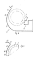
- Fig. 4 ein Querstromgebläse schematisch im Schnitt und
- Fig.5 5 einen Teilschnitt eines Querstromgebläses.
- 1 is a cross-flow fan schematically in section,
- 2 shows a vortex former modified embodiment,
- 3 is a graph,
- Fig. 4 shows a cross-flow fan schematically in section and
- Fig.5 5 is a partial section of a cross-flow fan.
In den Figuren ist mit 1 ein Laufrad bekannter Ausführung bezeichnet, das im Umfangsbereich eine Anzahl Luftschaufeln 2 aufweist. Das Laufrad 1 dreht in einem Gehäuse 3, das durch ein erstes Wandstück 4 und zweites als Wirbelbildner dienendes Wandstück 15 gebildet ist. Das Wandstück 15 weist einen Anströmbogen 5 auf, an dem sich in Umfangsdrehrichtung des Laufrades 1 erfindungsgemäß eine weitgehend ebene Schaufelkanalbrücke 6 anschließt, die durch eine Abkröpfung 7 begrenzt ist. An der Abkröpfung 7 schließt sich an dem der Schaufelkanalbrücke 6 abgewandten Ende eine ebene Zunge 8 an. Die Schaufelkanalbrücke 6 und die Zunge 8 erstrecken sich über ein bis zwei Schaufelteilungen, wobei die Schaufelkanalbrücke 60 bis 70 Grad zur Horizontalen und die Zunge 70 bis 80 Grad zur Horizontalen geneigt sind.In the figures, 1 denotes an impeller of known design, which has a number of
Bei Umläufen des Laufrades 1 wird in bekannter Weise im Bereich des Anströmbogens 5 ein Drehklang entsprechend der Kurve 14 der Fig. 3 erzeugt, der sich als unangenehmer Pfeifton bemerkbar macht. Darüber hinaus sorgen die Kante 9 am Eingang der Abkröpfung 7 und die Kante 10 am Ende der Zunge 8 für die Erzeugung eines zweiten, künstlichen Drehklangs entsprechend der Kurv» 15' der Fig. 3, der mit gleicher Amplitude aber um 180 Grad versetzt den . ersterwähnten Drehltlang mit dem Resultat der gegenseitigen Auslöschung überlagert. Durch Annähern der Kante 10 wird die Intensität (Amplitude) des künstlichen Drehklanges verändert, während die Länge der Zunge Einfluß auf die Phasenlage hat.When the impeller 1 rotates, a rotary sound corresponding to the
In Richtung der Austrittsströmung schließt sich am Anströmbogen 5 ein Wandstück 11 mit einem ebenen Abschnitt 11' und einer Abkröpfung 12 als obere Begrenzung des Austrittskanals 13 an. Im Steg 12' der Abkröpfung 12 sind Injektorbohrungen 14 vorgesehen. Über die Injektorbohrungen 14 erfolgt bei großen Strömungsgeschwindigkeiten eine zusätzliche Luftansaugung, was zu einer 5 bis 10 prozentigen Steigerung des Wirkungsgrades führt, während bei hohen Drükken die Sicherstellung einer Mindestluftmenge durch die Beschaufelung bewirkt werden kann, was ein Abreißen der Strömung verhindert.In the direction of the outlet flow, a
Schließlich erlauben die Injektorbohrungen auch die Erzeugung eines akustischen Kurzschlusses zwischen Druck- und Saugseite zur breitbandigen Geräuschreduzierung. Es versteht sich, daß die Injektorbohrungen auch durch anderweitige Lochungen, z. B. Schlitze ersetzt sein können.Finally, the injector holes also allow the generation of an acoustic short circuit between the pressure and suction side for broadband noise reduction. It goes without saying that the injector bores also through other perforations, for. B. slots can be replaced.
Beim Ausführungsbeispiel der Fig. 2 ist das als Austrittskanalbegrenzung dienende Wandstück 11 als rückseitige Fortsetzung des Stegs 7' der Abkröpfung 7 einstückig mit dieser ausgebildet.In the exemplary embodiment in FIG. 2, the
In Fig. 4 ist mit 1 wiederum ein an sich bekanntes Laufrad mit einer Anzahl Luftschaufeln 2 bezeichnet. Das Laufrad 1 dreht in einem Gehäuse 3, das durch ein erstes Gehäusewandstück 4 und ein als Wirbelbildner dienendes zweites Gehäusewandstück 15 gebildet ist. Das Gehäusewandstück 4 weist am einströmseitigen Ende eine sich über die engste Stelle 16 zwischen Gehäusewandstück 4 und Laufrad 1 hinaus erstrekkende Verlängerung 17 auf, deren radialer Abstand zum Laufrad 1 in Richtung des freien Endes zunimmt. Die Verlängerung 17 bildet eine trichterartige Verbreiterung, die die Einlaufgeräusche vermindert. Am freien Ende ist die Verlängerung 17 mit einer etwa rechtwinkelig ausgebogenen Leiste 18 versehen, deren Breite etwa einer Schaufelteilung entspricht. Die Leiste 18 ermöglicht das Erfassen des ganzen Strömungsfeldes und übt so Führungsfunktion für die Zuluft aus.In FIG. 4, 1 denotes an impeller known per se with a number of
Beim Querstromgebläse der Figur 5 ist die Verlängerung 17 an ihrem Ende zwar ebenfalls mit einer Leiste 18 versehen, jedoch ist an dieser eine weitere, horizontal gerichtete Leiste 19 angebogen, die die Führung der Zuluft unterstützt.In the cross-flow fan of FIG. 5, the
Claims (11)
Priority Applications (1)
| Application Number | Priority Date | Filing Date | Title |
|---|---|---|---|
| AT85111259T ATE51273T1 (en) | 1984-09-21 | 1985-09-06 | CROSS-FLOW BLOWER. |
Applications Claiming Priority (4)
| Application Number | Priority Date | Filing Date | Title |
|---|---|---|---|
| DE19843434639 DE3434639A1 (en) | 1984-09-21 | 1984-09-21 | Cross-current blower |
| DE3434638 | 1984-09-21 | ||
| DE19843434638 DE3434638A1 (en) | 1984-09-21 | 1984-09-21 | Cross-flow blower |
| DE3434639 | 1984-09-21 |
Publications (3)
| Publication Number | Publication Date |
|---|---|
| EP0175229A2 EP0175229A2 (en) | 1986-03-26 |
| EP0175229A3 EP0175229A3 (en) | 1987-09-30 |
| EP0175229B1 true EP0175229B1 (en) | 1990-03-21 |
Family
ID=25824931
Family Applications (1)
| Application Number | Title | Priority Date | Filing Date |
|---|---|---|---|
| EP19850111259 Expired - Lifetime EP0175229B1 (en) | 1984-09-21 | 1985-09-06 | Cross-current ventilator |
Country Status (1)
| Country | Link |
|---|---|
| EP (1) | EP0175229B1 (en) |
Families Citing this family (2)
| Publication number | Priority date | Publication date | Assignee | Title |
|---|---|---|---|---|
| EP0466983A1 (en) * | 1990-07-16 | 1992-01-22 | Crosslee Plc | Noise suppression |
| CN102374583B (en) * | 2010-08-17 | 2016-03-02 | 乐金电子(天津)电器有限公司 | Air conditioner room unit |
Family Cites Families (9)
| Publication number | Priority date | Publication date | Assignee | Title |
|---|---|---|---|---|
| DE807978C (en) * | 1950-02-08 | 1951-07-09 | Bruno Eck Dr Ing | Fan with drum runner |
| FR1252057A (en) * | 1959-04-15 | 1961-01-27 | Heating and ventilation device for rooms and objects | |
| GB973475A (en) * | 1961-03-08 | 1964-10-28 | Apsley Metal Products Ltd | Improvements in or relating to cross-flow blowers |
| US3144913A (en) * | 1962-08-31 | 1964-08-18 | Garrett Corp | Method and apparatus for attenuating helical acoustic pressure waves |
| FR1372102A (en) * | 1963-09-19 | 1964-09-11 | Cross-flow fan device or the like and its various applications | |
| US3813184A (en) * | 1972-12-01 | 1974-05-28 | Allis Chalmers | Inlet choke vane for transverse blower |
| DE2322734A1 (en) * | 1973-05-05 | 1974-11-21 | Buderus Eisenwerk | FAN |
| US4014625A (en) * | 1973-08-20 | 1977-03-29 | Teruo Yamamoto | Transverse flow fan |
| DE3326651A1 (en) * | 1983-07-23 | 1985-01-31 | Standard Elektrik Lorenz Ag, 7000 Stuttgart | CROSS-FLOW FAN |
-
1985
- 1985-09-06 EP EP19850111259 patent/EP0175229B1/en not_active Expired - Lifetime
Also Published As
| Publication number | Publication date |
|---|---|
| EP0175229A2 (en) | 1986-03-26 |
| EP0175229A3 (en) | 1987-09-30 |
Similar Documents
| Publication | Publication Date | Title |
|---|---|---|
| DE3012904C2 (en) | Bladed diffuser for a turbo machine | |
| DE10313054B4 (en) | centrifugal blower | |
| DE4212653B4 (en) | compressor | |
| DE2837543A1 (en) | Fume hood | |
| DE2744366A1 (en) | IMPELLER FOR A RADIAL TURBO COMPRESSOR | |
| DE1428191A1 (en) | Centrifugal blower | |
| DE19602368A1 (en) | Radial fan | |
| DE102016007205A1 (en) | fan unit | |
| DE3506452A1 (en) | MUFFLER WITH LEADING BLADES ON THE SUCTION SIDE OF THE COMPRESSOR OF AN EXHAUST GAS TURBOCHARGER | |
| DE3822267C2 (en) | ||
| EP0175229B1 (en) | Cross-current ventilator | |
| DE10017808B4 (en) | Housing for a blower, especially a radial blower | |
| DE2524556A1 (en) | AXIAL FLOW FAN WITH SINGLE SUCTION | |
| DE2538162A1 (en) | PUMP SUPPLY | |
| DE2414610C3 (en) | Cross-flow fan | |
| DE10319270A1 (en) | Centrifugal blower with a centrifugal fan arranged in a spiral housing | |
| DE2545036A1 (en) | HOUSING FOR A CROSS-FLOW FAN | |
| DE1601627C3 (en) | Cooled blade for a flow machine | |
| EP0845600A2 (en) | Side-channel machine | |
| DE102014208127A1 (en) | Radial fan with improved leading edge geometry | |
| EP1046822B1 (en) | Blower and scroll casing | |
| DE2531740A1 (en) | Toroidal rotary blower - has block separating inlet and outlet ports with vanes masking each | |
| DE1403495A1 (en) | Radial blower, especially for combine harvesters | |
| DE102005040305B4 (en) | Side channel machine | |
| DE19751322C2 (en) | Suction head on a vacuum cleaner |
Legal Events
| Date | Code | Title | Description |
|---|---|---|---|
| PUAI | Public reference made under article 153(3) epc to a published international application that has entered the european phase |
Free format text: ORIGINAL CODE: 0009012 |
|
| AK | Designated contracting states |
Kind code of ref document: A2 Designated state(s): AT BE CH FR GB IT LI LU NL SE |
|
| RBV | Designated contracting states (corrected) |
Designated state(s): AT CH FR GB IT LI NL |
|
| 17P | Request for examination filed |
Effective date: 19860827 |
|
| PUAL | Search report despatched |
Free format text: ORIGINAL CODE: 0009013 |
|
| AK | Designated contracting states |
Kind code of ref document: A3 Designated state(s): AT CH FR GB IT LI NL |
|
| 17Q | First examination report despatched |
Effective date: 19880831 |
|
| GRAA | (expected) grant |
Free format text: ORIGINAL CODE: 0009210 |
|
| AK | Designated contracting states |
Kind code of ref document: B1 Designated state(s): AT CH FR GB IT LI NL |
|
| PG25 | Lapsed in a contracting state [announced via postgrant information from national office to epo] |
Ref country code: NL Effective date: 19900321 Ref country code: IT Free format text: LAPSE BECAUSE OF FAILURE TO SUBMIT A TRANSLATION OF THE DESCRIPTION OR TO PAY THE FEE WITHIN THE PRESCRIBED TIME-LIMIT;WARNING: LAPSES OF ITALIAN PATENTS WITH EFFECTIVE DATE BEFORE 2007 MAY HAVE OCCURRED AT ANY TIME BEFORE 2007. THE CORRECT EFFECTIVE DATE MAY BE DIFFERENT FROM THE ONE RECORDED. Effective date: 19900321 Ref country code: GB Effective date: 19900321 Ref country code: FR Effective date: 19900321 |
|
| REF | Corresponds to: |
Ref document number: 51273 Country of ref document: AT Date of ref document: 19900415 Kind code of ref document: T |
|
| EN | Fr: translation not filed | ||
| NLV1 | Nl: lapsed or annulled due to failure to fulfill the requirements of art. 29p and 29m of the patents act | ||
| PG25 | Lapsed in a contracting state [announced via postgrant information from national office to epo] |
Ref country code: AT Effective date: 19900906 |
|
| GBV | Gb: ep patent (uk) treated as always having been void in accordance with gb section 77(7)/1977 [no translation filed] | ||
| PG25 | Lapsed in a contracting state [announced via postgrant information from national office to epo] |
Ref country code: LI Effective date: 19900930 Ref country code: CH Effective date: 19900930 |
|
| PLBE | No opposition filed within time limit |
Free format text: ORIGINAL CODE: 0009261 |
|
| STAA | Information on the status of an ep patent application or granted ep patent |
Free format text: STATUS: NO OPPOSITION FILED WITHIN TIME LIMIT |
|
| 26N | No opposition filed | ||
| REG | Reference to a national code |
Ref country code: CH Ref legal event code: PL |