EP0174013B1 - Optical connector and method of manufacturing a pair of ferrules therefor - Google Patents
Optical connector and method of manufacturing a pair of ferrules therefor Download PDFInfo
- Publication number
- EP0174013B1 EP0174013B1 EP85111146A EP85111146A EP0174013B1 EP 0174013 B1 EP0174013 B1 EP 0174013B1 EP 85111146 A EP85111146 A EP 85111146A EP 85111146 A EP85111146 A EP 85111146A EP 0174013 B1 EP0174013 B1 EP 0174013B1
- Authority
- EP
- European Patent Office
- Prior art keywords
- fiber
- ferrules
- connector
- coated
- pair
- Prior art date
- Legal status (The legal status is an assumption and is not a legal conclusion. Google has not performed a legal analysis and makes no representation as to the accuracy of the status listed.)
- Expired - Lifetime
Links
Images




Classifications
-
- G—PHYSICS
- G02—OPTICS
- G02B—OPTICAL ELEMENTS, SYSTEMS OR APPARATUS
- G02B6/00—Light guides; Structural details of arrangements comprising light guides and other optical elements, e.g. couplings
- G02B6/24—Coupling light guides
- G02B6/36—Mechanical coupling means
- G02B6/38—Mechanical coupling means having fibre to fibre mating means
- G02B6/3807—Dismountable connectors, i.e. comprising plugs
- G02B6/3873—Connectors using guide surfaces for aligning ferrule ends, e.g. tubes, sleeves, V-grooves, rods, pins, balls
- G02B6/3885—Multicore or multichannel optical connectors, i.e. one single ferrule containing more than one fibre, e.g. ribbon type
-
- B—PERFORMING OPERATIONS; TRANSPORTING
- B29—WORKING OF PLASTICS; WORKING OF SUBSTANCES IN A PLASTIC STATE IN GENERAL
- B29C—SHAPING OR JOINING OF PLASTICS; SHAPING OF MATERIAL IN A PLASTIC STATE, NOT OTHERWISE PROVIDED FOR; AFTER-TREATMENT OF THE SHAPED PRODUCTS, e.g. REPAIRING
- B29C45/00—Injection moulding, i.e. forcing the required volume of moulding material through a nozzle into a closed mould; Apparatus therefor
- B29C45/14—Injection moulding, i.e. forcing the required volume of moulding material through a nozzle into a closed mould; Apparatus therefor incorporating preformed parts or layers, e.g. injection moulding around inserts or for coating articles
- B29C45/14467—Joining articles or parts of a single article
-
- G—PHYSICS
- G02—OPTICS
- G02B—OPTICAL ELEMENTS, SYSTEMS OR APPARATUS
- G02B6/00—Light guides; Structural details of arrangements comprising light guides and other optical elements, e.g. couplings
- G02B6/24—Coupling light guides
- G02B6/36—Mechanical coupling means
- G02B6/38—Mechanical coupling means having fibre to fibre mating means
- G02B6/3807—Dismountable connectors, i.e. comprising plugs
- G02B6/3833—Details of mounting fibres in ferrules; Assembly methods; Manufacture
-
- G—PHYSICS
- G02—OPTICS
- G02B—OPTICAL ELEMENTS, SYSTEMS OR APPARATUS
- G02B6/00—Light guides; Structural details of arrangements comprising light guides and other optical elements, e.g. couplings
- G02B6/24—Coupling light guides
- G02B6/36—Mechanical coupling means
- G02B6/38—Mechanical coupling means having fibre to fibre mating means
- G02B6/3807—Dismountable connectors, i.e. comprising plugs
- G02B6/3833—Details of mounting fibres in ferrules; Assembly methods; Manufacture
- G02B6/3865—Details of mounting fibres in ferrules; Assembly methods; Manufacture fabricated by using moulding techniques
-
- G—PHYSICS
- G02—OPTICS
- G02B—OPTICAL ELEMENTS, SYSTEMS OR APPARATUS
- G02B6/00—Light guides; Structural details of arrangements comprising light guides and other optical elements, e.g. couplings
- G02B6/24—Coupling light guides
- G02B6/36—Mechanical coupling means
- G02B6/38—Mechanical coupling means having fibre to fibre mating means
- G02B6/3807—Dismountable connectors, i.e. comprising plugs
- G02B6/3873—Connectors using guide surfaces for aligning ferrule ends, e.g. tubes, sleeves, V-grooves, rods, pins, balls
-
- G—PHYSICS
- G02—OPTICS
- G02B—OPTICAL ELEMENTS, SYSTEMS OR APPARATUS
- G02B6/00—Light guides; Structural details of arrangements comprising light guides and other optical elements, e.g. couplings
- G02B6/24—Coupling light guides
- G02B6/36—Mechanical coupling means
- G02B6/38—Mechanical coupling means having fibre to fibre mating means
- G02B6/3807—Dismountable connectors, i.e. comprising plugs
- G02B6/389—Dismountable connectors, i.e. comprising plugs characterised by the method of fastening connecting plugs and sockets, e.g. screw- or nut-lock, snap-in, bayonet type
-
- G—PHYSICS
- G02—OPTICS
- G02B—OPTICAL ELEMENTS, SYSTEMS OR APPARATUS
- G02B6/00—Light guides; Structural details of arrangements comprising light guides and other optical elements, e.g. couplings
- G02B6/24—Coupling light guides
- G02B6/36—Mechanical coupling means
- G02B6/38—Mechanical coupling means having fibre to fibre mating means
- G02B6/3807—Dismountable connectors, i.e. comprising plugs
- G02B6/3873—Connectors using guide surfaces for aligning ferrule ends, e.g. tubes, sleeves, V-grooves, rods, pins, balls
- G02B6/3874—Connectors using guide surfaces for aligning ferrule ends, e.g. tubes, sleeves, V-grooves, rods, pins, balls using tubes, sleeves to align ferrules
- G02B6/3875—Floatingly supported sleeves
-
- G—PHYSICS
- G02—OPTICS
- G02B—OPTICAL ELEMENTS, SYSTEMS OR APPARATUS
- G02B6/00—Light guides; Structural details of arrangements comprising light guides and other optical elements, e.g. couplings
- G02B6/24—Coupling light guides
- G02B6/36—Mechanical coupling means
- G02B6/38—Mechanical coupling means having fibre to fibre mating means
- G02B6/3807—Dismountable connectors, i.e. comprising plugs
- G02B6/3873—Connectors using guide surfaces for aligning ferrule ends, e.g. tubes, sleeves, V-grooves, rods, pins, balls
- G02B6/3874—Connectors using guide surfaces for aligning ferrule ends, e.g. tubes, sleeves, V-grooves, rods, pins, balls using tubes, sleeves to align ferrules
- G02B6/3877—Split sleeves
Definitions
- the present invention generally relates to an optical connector for optical fibers required to be coupled with each other and a method of manufacturing a pair of ferrules for the optical connector.
- a cylindrical ferrule 3 made of metal has a flange 6 and is formed, at its axis, with a stepped through-hole, i.e., a hole 5' and an aperture 5 having a diameter smaller than that of the hole 5' and extending in alignment with the hole 5'.
- the single-core coated fiber 1 is constituted by one single-mode optical fiber having a coating therearound, while an exposed fiber (glass portion) 2 is obtained by removing the coating from an end portion of the coated fiber 1.
- the coated fiber 1 and the exposed fiber 2 are, respectively, fitted into the hole 5' and the aperture 5 until the coated fiber 1 is blocked by a bottom face of the hole 5'. Subsequently, adhesive 4 is filled into a gap between the coated fiber 1 and the hole 5' and thus, the coated fiber 1 is secured to the ferrule 3. Thereafter, a portion of the exposed fiber 2, which projects out of a corresponding end face of the ferrule 3, is cut off from the exposed fiber 2 and then, the cut edge of the exposed fiber 2 received by the aperture 5 is finished by grinding so as to be flush with the end face of the ferrule 3 such that the end face of the ferrule 3 acts as a coupling face of the ferrule 3.
- a sleeve having an inside diameter identical with an outside diameter of the ferrule 3 is prepared.
- a pair of the ferrules 3 each having the coated fiber 1 secured thereto are inserted into opposite ends of the sleeve, respectively until the respective coupling faces of the ferrules 3 are brought into contact with each other, so that the optical connector is obtained.
- a single-mode optical fiber has an outside diameter of 125 ⁇ m but its core diameter is merely 10 ⁇ m, far smaller than the outside diameter of the optical fiber. Accordingly, the optical fiber is required to be positioned with an accuracy of not more than 1 ⁇ m. For example, in order to obtain a transmission loss of not more than 1 dB at the optical connector, an eccentricity of the aperture 5 relative to an outside diameter of, e.g., 2.5 mm of the ferrule 3 is required to be restricted to 1 ⁇ m at its maximum, thereby resulting in an extreme rise in production cost of the prior art optical connector.
- the transmission loss at the optical connector exceeds 1 dB when an eccentricity of a core of the optical fiber relative to a cladding of the optical fiber is more than 1 ⁇ m. Therefore, in order to prevent such a phenomenon, the outside diameter of the ferrule 3 is required to be subjected to grinding coaxially with the core of the exposed fiber 2, but such grinding leads to low productivity rate and high production cost of the known optical connector.
- a rectangular ferrule 7 is formed with a pair of guide holes 8, each for receiving a coupling pin.
- the multiple optical fibers are, respectively, fitted into stepped through-holes arranged linearly so as to be disposed between the guide holes 8 and then, the coated fiber 1 is secured to the ferrule 7. Thereafter, the end face of the ferrule 7, out of which the exposed fibers 2 project, are ground into a coupling face of the ferrule 7.
- the known ferrules 3 and 7 require areas of about 5 mm2 and about 10 mm2 per optical fiber, respectively, which are approximately ten times a cross-sectional area of about 0.6 mm2 of the' coated fiber 1, thus preventing the known optical connectors of Figs. 1 and 2 from being made compact in size.
- the exposed fiber 2 obtained by removing the coating from the coated fiber 1 means generally a "bare optical fiber” and removal of the coating means "removal of only a coating for making positioning of the optical fiber unstable". Accordingly, for example, a thin film of 1 to 10 ⁇ m in thickness coated on a surface of the bare optical fiber is not required to be removed. Furthermore, even if a coating layer has a thickness of as large as 200 ⁇ m, it is needless to say that the coating layer is not required to be removed if the coating layer is sufficiently brought into close contact with the bare optical fiber without adversely effecting positioning of the optical fiber at all.
- JP-A-59-88712 shows a connector and a method of producing a connector in which two ferrules are loaded into a mold and a wire is drawn through the mold as a replacement for an optical fiber. This wire is put under tension by tensioning devices and then the cavity of the mold is filled with resin. Subsequently, the wire is withdrawn and the complete connector is then cut in two.
- the connector has two flanges which are located in housings.
- JP-A-54-160248 shows a method of forming a connector for a multiple of fiber optic cables in which the cables are located in a mold and then the mold is filled with resin to form a resin block. This block is then separated and located in a housing.
- the housing can be provided with pins which serve to locate the housings together in the proper way. Alternatively, and additionally, the screws may be used for securing the housing together.
- guide pins and optical fibers are arranged in parallel so as to be molded collectively into a molded item and guide bores are formed by withdrawing the guide pins from the molded item such that the cut optical connectors are positioned by using the guide pins so as to be coupled with each other again.
- JP-A-59-28113 describes a method of producing a non-separable connector in which the two fibers are butted together and connected by melt fixing (welding). The joint is then covered with adhesive and a heat shrinkable tube is then shrunk down onto the complete assembly in order to melt the adhesive and to produce a rigid support to the joint.
- melt fixing welding
- a heat shrinkable tube is then shrunk down onto the complete assembly in order to melt the adhesive and to produce a rigid support to the joint.
- As an additional reinforcement to the joint there is also a part which is not explained in the abstract but appears to be a metal or plastic rod which is used for reinforcings.
- JP-A-58-27122 describes an optical connector plug consisting of a plastic pipe body which has a continuously formed small hole slightly larger than the outside diameter of an optical fiber and a through-hole of a larger diameter.
- the central part of the plug is covered by a cylindrical metal, ceramic, or glass collar forming a concentric structure with the plastic plug body.
- the fitting surface of the plug is therefore abrasion resistant.
- the cylindrical collar is made of metal, high accuracy of machining and strong mechanical properties can be achieved.
- an essential object of the present invention is to provide an optical connector which is highly accurate and minimizes a transmission loss, with substantial elimination of the disadvantages inherent in conventional optical connectors of this kind.
- Another important object of the present invention is to provide an optical connector of the above described type, which is simple in structure and suitable for mass production at low cost.
- Still another object of the present invention is to provide a method of manufacturing a pair of ferrules for the above described optical connector, which produces a high productivity rate.
- an optical connector for joining substantially denuded fiber ends of coated optical fibers, comprising: a pair of molded ferrules each ferrule having a flange, and each ferrule being integrally molded with one of said coated fibers and a metal pipe by using molding resin wherein the associated coated fiber extends through said metal pipe such that the denuded fiber end is disposed at a distal end of said metal pipe; and each flange has a hole; a coupling pin fitted through said holes of said ferrules; a sleeve into which said metal pipes of said ferrules are fitted from opposite ends of said sleeve, respectively; and a housing member for axially clamping and maintaining said ferrules in abutment.
- Figs. 1a and 1b are a longitudinal sectional view and a front elevational view of a ferrule of a prior art single-fiber connector for a single-mode optical fiber, respectively (already referred to);
- Figs. 2a and 2b are a longitudinal sectional view and a front elevational view of a ferrule of a prior art multi-fiber connector, respectively (already referred to);
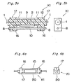
- Figs. 3a and 3b are a longitudinal sectional view and a front elevational view of a single-fiber connector according to a first embodiment of the present invention, respectively;
- Figs. 4a and 4b are a side elevational view and a front elevational view of the optical connector of Fig. 3 clamped by a clamp housing, respectively;
- Fig. 5 is a view explanatory of a method of the present invention of manufacturing a pair of ferrules of the optical connector of Fig. 3;
- Fig. 6 is a view explanatory of fusion bonding of exposed fibers coupled by the optical connector of Fig. 3;
- Figs. 7a and 7b are a longitudinal sectional view and a front elevational viev of a modified ferrule employed in the optical connector of Fig. 3, respectively;
- Figs. 8 and 9 are views similar to Fig. 3b, particularly showing modifications thereof, respectively;
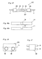
- Fig. 10 is an exploded view of a multi-fiber connector according to a second embodiment of the present invention.
- Fig. 11 is a front elevational view of a ferrule employed in the optical connector of Fig. 10;
- Figs. 12a and 12b are a side elevational view and a front elevational view of a clamp housing for clamping the optical connector of Fig. 10, respectively;
- Fig. 13 is a schematic view indicative of assembly of the optical connector of Fig. 10;
- Figs. 14a to 14f are views similar to Fig. 11, particularly showing various configurations of its multicore coated fiber, respectively;
- Fig. 15 is a view explanatory of a method of the present invention of manufacturing a pair of the ferrules of Fig. 11;
- Figs. 16a and 16b are a top plan view and a side elevational view of a modified pipe employed in the ferrule of Fig. 11, respectively;
- Fig. 17 is a view of a housing molded integrally with sleeves employed in the optical connector of Fig. 10;
- Fig. 18 is a view similar to Fig. 11, particularly showing a modification thereof.
- the optical connector K1 includes a pair of ferrules 17 of substantially cylindrical shape. Each of the ferrules 17 is provided with a metal pipe 11 and a rectangular flange 16 and has a hole 8 formed on the flange 16.
- An exposed fiber 2 is obtained by removing a coating from a portion of the coated fiber 1. After the exposed fiber 2 has been inserted into the metal pipe 11, the exposed fiber 2 is integrally molded with the metal pipe 11 by molding resin 12. Accordingly, the flange 16 formed with the hole 8 is integrally molded with the metal pipe 11. Since the bore of the metal pipe 11 is filled with the molding resin 8, the exposed fiber 2 is secured in position.
- a pair of the ferrules 17 each having the exposed fiber 2 molded therewith are, respectively, inserted into opposite ends of a sleeve 9 so as to be fitted into the sleeve 9 such that confronting end faces of the ferrules 17 are brought into contact with each other. Subsequently, a coupling pin 10 is fitted through the holes 8 of the confronting ferrules 17 so as to radially position the confronting ferrules 17, so that the optical connector K1 is obtained.
- the optical connector K1 further includes a clamp housing 20 for axially clamping the confronting ferrules 17 to each other as shown in Fig. 4.
- the clamp housing 20 is formed by an elastic metal plate so as to axially clamp the flanges 16 of the confronting ferrules 17 to each other.
- the clamp housing 20 is of one-piece construction but may be replaced by any clamp member constituted by a plurality of components. Such clamp member can also be employed for radially clamping the ferrules 17.
- a molding die 13 for molding the two ferrules 17 of the optical connector K1 simultaneously is composed of two die portions split in its longitudinal direction. Meanwhile, a pour-spout, runners, etc. of the molding die 13 are not illustrated for the sake of brevity.
- One coated fiber 1 having the exposed fiber 2 is inserted through the confronting metal pipes 11. Thereafter, a clamp member 14 split into two halves is interposed between the confronting metal pipes 11 and is bonded to the confronting end faces of the confronting metal pipes 11.
- the coated fiber 1 having the exposed fiber 2 is set in the molding die 13 coaxially with the confronting metal pipes 11 aligned axially with each other such that the coated fiber 1 extends out of opposite ends of the molding die 13.
- a molding pin 15 is set in a corresponding portion of the molding die 13 in parallel with the axially aligned metal pipes 11.
- the metal pipe 11 is integrally molded with the flange 16 and the flange 16 is formed with the hole 8, while the bore of the metal pipe 11 is filled with the molding die 12 in the same manner as the flange 16. Thereafter, the molded item is released from the molding die 13 and then, the molding pin 15 is withdrawn from the molded item. Then, the molded item is split into the two ferrules 17 by, for example, cutting the exposed fiber 2, i.e., a central portion of the molded item, whereby a pair of the ferrules 17 for the optical connector K1 can be obtained simultaneously.
- one coated fiber 1 having the exposed fiber 2 obtained by removing the coating from the coated fiber 1 is employed but can be replaced by one coated fiber 1 of Fig. 6 which is obtained by fusion bonding opposite ends 19 of two exposed fibers 2 of respective two coated fibers 1.
- the metal pipe 11 is formed, at e.g., an inner periphery or inner and outer peripheries thereof, with indentations or threads as shown in Fig. 7, a contact area between the metal pipe 11 and the molding die 12 increases and thus, it becomes possible to prevent the molding die 12 and the metal pipe 11 from being separated from each other.
- the single-core coated fiber 1 is employed in the optical connector K1.
- the present invention can also be applied to multicore coated fibers having, for example, five and 20 optical fibers, respectively as shown in Figs. 8 and 9.
- the multicore coated fiber having five optical fibers is inserted through the confronting metal pipes 11 by using a molding die similar to the above described molding die 13 such that the five optical fibers are arranged in parallel with one another and then, integral molding of the two ferrules of the optical connector K1' is performed by using the molding resin 12.
- each of the ferrules of the optical connector K1' is formed with the hole 8.
- two metal pipes 11 are integrally molded with the flanges 16 of the confronting ferrules 17 but can be replaced by one metal pipe 11 of a proper length as shown by imaginary lines in Fig. 5.
- the coated fiber 1 having the exposed fiber 2 is supported coaxially with the metal pipe 11 and then, integral molding of the confronting ferrules 17 is performed by the molding resin 12. It is needless to say that this arrangement can also be applied to multicore coated fibers. Then, the integrally molded item thus obtained is split into the two ferrules 17 by cutting the metal pipe 11.
- the cut faces of the metal pipe 11 are machined so as to finish the cut edges of the exposed fibers 2 and thus, the coupling faces of the respective ferrules 17 are produced.
- the hole 8 for receiving the coupling pin 10 is likewise formed on the flange 16 of each of the ferrules 17 at the time of the integral molding in order to radially position the confronting ferrules 17 accurately.
- the ferrule 17 has such configurations as shown in Fig. 3.
- the metal pipe 11 has an outside diameter of 2.5 mm.
- the flange 16 is of rectangular shape and has a thickness of 6 mm.
- the hole 8 has a diameter of 1 mm.
- the metal pipe 11 is formed with internal threads so as to be fitted into the sleeve 9.
- a portion of the metal pipe 11, which is fitted into the sleeve 9, has a length of about 8 mm.
- the flange 16 has a length of above 6.5 mm and a width of about 4.5 mm.
- the ferrule 17 is of an overall length of 18 mm.
- a transmission loss due to the fusion bonding is 0.04 dB on the average.
- the exposed fiber 2 has a length of about 10 mm.
- a pair of the metal pipes 11 having the coated fiber 1 inserted therethrough are set in the molding die 13 and, at the same time the molding pin 15 is also set in the molding die 13. Subsequently, the two die portions of the molding die 13 are clamped to each other and then, integral molding of the ferrules 17 is performed by using epoxy resin usable for low-pressure molding.
- the integral molding is performed at a molding pressure of 20 kg/cm2 and at a molding temperature of 170°C for five minutes. Thereafter, the integrally molded item is released from the molding die 13. Then, the molding pin 15 is withdrawn from the integrally molded item. The molded item is cut at its two locations interposing therebetween the central portion of the molded item, i.e., the fusion bonding point 19 of the exposed fiber 2. Then, the cut faces of the ferrules 17 thus obtained are ground so as to finish the cut edges of the exposed fibers 2. In consideration of the mold shrinkage factor, the molding pipe 15 is formed slightly larger, in size, than the coupling pin 10.
- a transmission loss due to coupling of the ferrules 17 by using the sleeve 9 and the coupling pin 10 was 0.57 dB on the average of a total of 20 samples and was 0.87 dB at its maximum. These values of the transmission loss are substantially similar to those of multimode optical connectors. Therefore, it will be readily understood that the optical connector of the present invention is fully suitable for practical use. Meanwhile, in this example, a split sleeve was employed as the sleeve 9 but may be replaced by an unsplit precision sleeve. Furthermore, the two exposed fibers 2 coupled with each other at the fusion bonding point 19 were employed in this example but can be replaced by the exposed fiber 2 obtained by partially removing the coating from the coated fiber 1.
- the single-mode optical fiber is mainly employed.
- the present invention can be applied to a multimode optical fiber or a multi-fiber connector for a multicore coated fiber as referred to earlier.
- the metal pipes having the coated fibers inserted therethrough and the molding pin are set in the molding die so as to produce the integrally molded item and then, the molded item is cut into a pair of the ferrules each having the coated fiber.
- a pair of the ferrules each having the coated fiber required to be coupled highly accurately can be easily manufactured quickly by the integral molding using the molding resin, thereby remarkably improving the productivity and reducing production cost of the ferrules.
- the ferrule since the ferrule has the metal pipe provided on its outer periphery, irregularity of the outside diameter of the ferrule can be drastically eliminated as compared with a ferrule composed wholly of the molding resin and the ferrule has an increased bending strength of not less than 8 kg on the average.
- the ferrule Since the ferrule is provided with the metal pipe to be fitted into the sleeve, the ferrule has such excellent wear resistance at the time of fitting of the ferrule into the sleeve and detaching of the ferrule from the sleeve that variations in transmission loss after the ferrule has been fitted into or detached from the sleeve 1,000 times are + 0.2 dB or less, thereby resulting in fairly excellent coupling reproducibility of the single-mode optical connector.
- the fusion bonding point of the exposed fiber is set at the clamp member for clamping the exposed fiber in a process of cutting the integrally molded item after integral molding of the fusion bonded exposed fiber, a distance between the confronting metal pipes is determined by the clamp member. Therefore, by the process of cutting the integrally molded item after the integral molding, it becomes possible to remove the fusion bonding point without fail and thus, the fusion bonding point of the exposed fiber is advantageously removed from the ferrule.
- the integrally molded item is manufactured by using a single metal pipe without using two metal pipes, the single metal pipe can be set in the molding die more easily than the two metal pipes. If the integrally molded item having the single metal pipe is cut, at its portion corresponding to the exposed fiber, into a pair of the ferrules, the ferrules thus obtained function in the same manner as those obtained by using the two metal pipes.
- the optical connector K2 includes a pair of ferrules 27.
- Each of the ferrules 27 is provided with a plurality of, for example, two coupling portions 18 each formed by a metal pipe 11 (Fig. 15) and has a rectangular flange 26.
- Each of the ferrules 27 further has a portion 26' from which two multicore coated fibers 1 each having multiple, e.g., three optical fibers are inserted.
- Each of the ferrules 27 is formed by the two coated fibers 1, the flange 26, the portion 26', etc. which are molded integrally with one another by using molding resin 12 (Fig. 15).
- the coated fibers 1 each having multiple exposed fibers 2 are secured to a pair of the ferrules 27 by the molding resin 12 in a molding die to be described later such that the exposed fibers 2 are disposed in the metal pipe 11.
- the multicore coated fibers 1 are of tape type but can be replaced by multicore coated fibers of any type.
- each of the ferrules 27 the multiple exposed fibers 2 are secured to each of the coupling portions 18 each formed by the metal pipe 11 such that cut edges of the exposed fibers 2 coincide, in position, with an end face of the metal pipe 11.
- Each of the coupling portions 18 of one of a pair of the ferrules 27 is coupled, through a sleeve 9, with that of the other one of a pair of the ferrules 27 so as to couple a pair of the ferrules 27 with each other.
- a clamp housing 22 (Fig. 12) made of elastic material for axially clamping the confronting ferrules 27 to each other is brought into engagement with the flanges 26 of the confronting ferrules 27, whereby the multi-fiber connector K2 is obtained as shown in Fig. 13.
- each of the ferrules 27 is provided with the two coupling portions 18 each having the multicore coated fiber 1 constituted by the three optical fibers but can be modified variously as shown in Figs. 14a to 14f.
- each of the coupling portions 18 ha a single-core coated fiber constituted by a single optical fiber.
- each of the ferrules 27 is provided with three or four coupling portions 18 each having the multicore coated fiber 1 constituted by the multiple optical fibers such that the multiple optical fibers of the coupling portions 18 axially extend in parallel with one another. It was found in the present invention that each of the coupling portions 18 having an outside diameter of 2.5 mm is capable or accommodating up to 20 optical fibers.
- a molding die 23 for molding a pair of the ferrules 27 of the optical connector K2 is constituted by, for example, two die portions split in its longitudinal direction.
- each of the ferrules 27 is provided with the two coated fibers 1, the flange 26, the portion 26' for receiving the coated fibers 1 and support portions for supporting the two metal pipes 11.
- the multiple exposed fibers 2 obtained by removing the coating from each of the coated fibers 1 are inserted through each of the metal pipes 11 so as to be used, in common, for a pair of the ferrules 27 such that the two metal pipes 11 each covering the multiple exposed fibers 2 are bridged in parallel with each other between corresponding portions of the flanges 26 of the confronting ferrules 27 in the molding die 23. Meanwhile, opposite ends of each of the coated fibers 1 are projected out of opposite ends of the molding die 23. Subsequently, after the two die portions of the molding die 23 have been clamped to each other, molding resin 12, for example, epoxy resin is injected into the molding die 23. As shown in Fig. 16, each of the metal pipes 11 may be formed, at a central portion thereof, with a slot or an opening 31 for degassing at the time of molding a pair of the ferrules 27.
- the two metal pipes 11 are molded integrally with the flanges 26 of the confronting ferrules 27 and the molding resin 12 is sufficiently filled into a space between each of the metal pipes 11 and each of the coated fibers 1 so as to secure each of the coated fibers 1 to each of the metal pipes 11.
- An integrally molded item thus obtained by using the molding resin 12 is released from the molding die 23 and then, is cut, at the metal pipes 11, into a pair of the ferrules 27. Subsequently, the cut edges of the exposed fibers 2 are ground at the end face of each of the metal pipes 11, whereby a pair of the ferrules 27 each provided with two or more coupling potions 18 each having the multicore coated fiber 1 can be obtained.
- a pair of the sleeves 9 are employed.
- the two coupling portions 18 of each of a pair of the ferrules 27 are inserted into the sleeves 9, respectively such that the two coupling portions 18 of one of the ferrules 27 confront the two coupling portions 18 of the other one of the ferrules 27, respectively.
- the flanges 26 of the confronting ferrules 27 are so supported by the clamp housing 22 as to be depressed towards each other, whereby the optical connector K2 is obtained.
- a pair of the sleeves 9 can be replaced by a housing 32 molded integrally with a pair of the sleeves 9 as shown in Fig. 17.
- Each of the sleeves 9 may be further replaced by a split metal sleeve or a ceramic sleeve.
- each of the metal pipes 11 may be formed, at its central portion, with a reduced diameter portion 30 as shown in Fig. 15. In this case, even if burrs are produced on the cut edge of the reduced diameter portion 30 of each of the confronting metal pipes 11, the burrs of the reduced diameter portion 30 are held out of contact with each of the sleeves 9 when the confronting metal pipes 11 are fitted into each of the sleeves 9, so that the confronting metal pipes 11 can be smoothly fitted into each of the sleeves 9.
- the coated fiber 1 may be provided, at the exposed fibers 2, with a fusion bonding point 19 as shown in Fig. 15.
- the molded item may be cut, at its two portions interposing therebetween the fusion bonding point 19 and spaced 3 to 5 mm from each other, into a pair of the ferrules 27 so as to remove the fusion bonding point 19 from the ferrules 27.
- the molded item is cut into a pair of the ferrules 27 in the state where the exposed fibers 2 are secured to each of the metal pipes 11. Accordingly, when the ferrules 27 are coupled with each other as the optical connector K2, the cut edges of the confronting metal pipes 11 substantially coincide with each other. More specifically, since each of the ferrules 27 has at least two metal pipes 11 molded integrally with the flange 26, the two metal pipes 11 each extending in the axial direction of the coated fiber 1 contribute greatly towards positioning of each of the ferrules 27 at the time of coupling of a pair of the ferrules 27.
- each of the two metal pipes 11 has a single-core coated fiber or a multicore coated fiber.
- one of the metal pipes 11 is not provided with the coated fiber so as to be used only for positioning each of the ferrules 27.
- the confronting ferrules 27 are not necessarily required to be disposed horizontally in the molding die 23, in which case the molding die 23 is split in its longitudinal direction.
- optical connector K2 employing two coupling portions 18 each having a tape type multicore coated fiber composed of five optical fibers is described, with each tape having a width of 1.6 mm and a thickness of 0.6 mm.
- the coated fiber is inserted through a metal pipe made of stainless steel and having an outside diameter of 2.499 + 0.001 mm by removing therefrom a coating of 20 mm in length.
- integral molding of a pair of the ferrules for the optical connector K2 is performed in the molding die by using low-pressure epoxy resin.
- the integrally molded item is released from the molding die and then, cut, at its central portion, into a pair of the ferrules.
- optical connector K2 In another example of the optical connector K2, two coupling portions each having a multicore coated fiber composed of three single-mode optical fibers are employed. In a total of ten optical connectors K2, it was found that the transmission loss at the optical connector K2 desirably assumes a small value of 0.20 dB on the average.
- the exposed fibers to be optically coupled with the mating exposed fibers at a subsequent step are secured in a plurality of the metal pipes by integral molding such that a plurality of the metal pipes position, as the coupling portions, each of a pair of the ferrules at the time of coupling of a pair of the ferrules. Accordingly, in accordance with the present invention, since the confronting coated fibers can be joined to each other accurately at a relative position substantially identical with that occupied at the time of the integral molding, the optical connector having a remarkably small transmission loss can be obtained without the need for carefully positioning a plurality of the exposed fibers at the time of the integral molding.
- each of a pair of the ferrules has two metal pipes each having an outside diameter of 2.5 mm and each of the metal pipes accommodates a multi-core coated fiber composed of ten optical fibers
- each of the ferrules requires only an area of 1 mm2 per optical fiber, which is one-tenth to one-fifth of that of prior art optical connectors.
- the multicore coated fiber composed of three single-core optical fibers, which constitutes a concentrated configuration three times that of prior art optical connectors.
- a transmission loss at the known single-mode optical connectors was at best 0.6 dB on the average even if matching agent is employed.
- the present invention it becomes possible to easily obtain a transmission loss of 0.2 dB at the optical connector. Namely, in the present invention, since a plurality of the metal pipes each having the multi-core coated fiber secured thereto position, as the coupling portions, each of the confronting ferrules without the need for provision of the coupling pins of the prior art ferrule of Fig. 2, the flange of each of the ferrules can be made small in size, thus making the optical connector compact in size.
- the optical connector is simplified in structure and can be manufactured at low cost.
Landscapes
- Physics & Mathematics (AREA)
- General Physics & Mathematics (AREA)
- Optics & Photonics (AREA)
- Engineering & Computer Science (AREA)
- Manufacturing & Machinery (AREA)
- Mechanical Engineering (AREA)
- Mechanical Coupling Of Light Guides (AREA)
Description
- The present invention generally relates to an optical connector for optical fibers required to be coupled with each other and a method of manufacturing a pair of ferrules for the optical connector.
- Conventionally, in a single-fiber connector for a single-core coated
fiber 1, it has been so arranged as shown in Figs. 1a and 1b of the accompanying drawings that acylindrical ferrule 3 made of metal has aflange 6 and is formed, at its axis, with a stepped through-hole, i.e., a hole 5' and anaperture 5 having a diameter smaller than that of the hole 5' and extending in alignment with the hole 5'. The single-core coatedfiber 1 is constituted by one single-mode optical fiber having a coating therearound, while an exposed fiber (glass portion) 2 is obtained by removing the coating from an end portion of the coatedfiber 1. The coatedfiber 1 and the exposedfiber 2 are, respectively, fitted into the hole 5' and theaperture 5 until the coatedfiber 1 is blocked by a bottom face of the hole 5'. Subsequently,adhesive 4 is filled into a gap between the coatedfiber 1 and the hole 5' and thus, the coatedfiber 1 is secured to theferrule 3. Thereafter, a portion of the exposedfiber 2, which projects out of a corresponding end face of theferrule 3, is cut off from the exposedfiber 2 and then, the cut edge of the exposedfiber 2 received by theaperture 5 is finished by grinding so as to be flush with the end face of theferrule 3 such that the end face of theferrule 3 acts as a coupling face of theferrule 3. Then, a sleeve having an inside diameter identical with an outside diameter of theferrule 3 is prepared. Thus, a pair of theferrules 3 each having the coatedfiber 1 secured thereto are inserted into opposite ends of the sleeve, respectively until the respective coupling faces of theferrules 3 are brought into contact with each other, so that the optical connector is obtained. - Meanwhile, for example, a single-mode optical fiber has an outside diameter of 125 µm but its core diameter is merely 10 µm, far smaller than the outside diameter of the optical fiber. Accordingly, the optical fiber is required to be positioned with an accuracy of not more than 1 µm. For example, in order to obtain a transmission loss of not more than 1 dB at the optical connector, an eccentricity of the
aperture 5 relative to an outside diameter of, e.g., 2.5 mm of theferrule 3 is required to be restricted to 1 µm at its maximum, thereby resulting in an extreme rise in production cost of the prior art optical connector. - Furthermore, even if the eccentricity of the
aperture 5 relative to the outside diameter of theferrule 3 is restricted to not more than 1 µm, the transmission loss at the optical connector exceeds 1 dB when an eccentricity of a core of the optical fiber relative to a cladding of the optical fiber is more than 1 µm. Therefore, in order to prevent such a phenomenon, the outside diameter of theferrule 3 is required to be subjected to grinding coaxially with the core of the exposedfiber 2, but such grinding leads to low productivity rate and high production cost of the known optical connector. - Meanwhile, as shown in Figs. 2a and 2b, in a prior art multi-fiber connector for a multicore coated
fiber 1 having multiple, e.g., five optical fibers, arectangular ferrule 7 is formed with a pair ofguide holes 8, each for receiving a coupling pin. In the same manner as the knownferrule 3 of Fig. 1, the multiple optical fibers are, respectively, fitted into stepped through-holes arranged linearly so as to be disposed between theguide holes 8 and then, the coatedfiber 1 is secured to theferrule 7. Thereafter, the end face of theferrule 7, out of which the exposedfibers 2 project, are ground into a coupling face of theferrule 7. After the respective coupling faces of a pair of theferrules 7 have been brought into contact with each other, a pair of the coupling pins are inserted through one pair of the confrontingguide holes 8 of the confrontingferrules 7 and the other pair of the confrontingguide holes 8 of the confrontingferrules 7, respectively so as to position the confrontingferrules 7. Subsequently, the confrontingferrules 7 positioned by a pair of the coupling pins are clamped by a clamp housing and thus, the optical connector is obtained. However, this known optical connector has such a drawback that theapertures 5 for receiving the exposedfibers 2, respectively are required to be machined with high positional accuracy relative to theguide holes 8, thereby resulting in rise of its production cost. - Moreover, the known
ferrules fiber 1, thus preventing the known optical connectors of Figs. 1 and 2 from being made compact in size. - It should be noted here that the exposed
fiber 2 obtained by removing the coating from the coatedfiber 1 means generally a "bare optical fiber" and removal of the coating means "removal of only a coating for making positioning of the optical fiber unstable". Accordingly, for example, a thin film of 1 to 10 µm in thickness coated on a surface of the bare optical fiber is not required to be removed. Furthermore, even if a coating layer has a thickness of as large as 200 µm, it is needless to say that the coating layer is not required to be removed if the coating layer is sufficiently brought into close contact with the bare optical fiber without adversely effecting positioning of the optical fiber at all. - JP-A-59-88712 shows a connector and a method of producing a connector in which two ferrules are loaded into a mold and a wire is drawn through the mold as a replacement for an optical fiber. This wire is put under tension by tensioning devices and then the cavity of the mold is filled with resin. Subsequently, the wire is withdrawn and the complete connector is then cut in two. The connector has two flanges which are located in housings.
- JP-A-54-160248 shows a method of forming a connector for a multiple of fiber optic cables in which the cables are located in a mold and then the mold is filled with resin to form a resin block. This block is then separated and located in a housing. The housing can be provided with pins which serve to locate the housings together in the proper way. Alternatively, and additionally, the screws may be used for securing the housing together.
- In this known connector, guide pins and optical fibers are arranged in parallel so as to be molded collectively into a molded item and guide bores are formed by withdrawing the guide pins from the molded item such that the cut optical connectors are positioned by using the guide pins so as to be coupled with each other again.
- The third citation, JP-A-59-28113 describes a method of producing a non-separable connector in which the two fibers are butted together and connected by melt fixing (welding). The joint is then covered with adhesive and a heat shrinkable tube is then shrunk down onto the complete assembly in order to melt the adhesive and to produce a rigid support to the joint. As an additional reinforcement to the joint there is also a part which is not explained in the abstract but appears to be a metal or plastic rod which is used for reinforcings.
- JP-A-58-27122 describes an optical connector plug consisting of a plastic pipe body which has a continuously formed small hole slightly larger than the outside diameter of an optical fiber and a through-hole of a larger diameter. The central part of the plug is covered by a cylindrical metal, ceramic, or glass collar forming a concentric structure with the plastic plug body. The fitting surface of the plug is therefore abrasion resistant. Where the cylindrical collar is made of metal, high accuracy of machining and strong mechanical properties can be achieved.
- Accordingly, an essential object of the present invention is to provide an optical connector which is highly accurate and minimizes a transmission loss, with substantial elimination of the disadvantages inherent in conventional optical connectors of this kind.
- Another important object of the present invention is to provide an optical connector of the above described type, which is simple in structure and suitable for mass production at low cost.
- Still another object of the present invention is to provide a method of manufacturing a pair of ferrules for the above described optical connector, which produces a high productivity rate.
- In order to accomplish these objects of the present invention, an optical connector is provided for joining substantially denuded fiber ends of coated optical fibers, comprising: a pair of molded ferrules each ferrule having a flange, and each ferrule being integrally molded with one of said coated fibers and a metal pipe by using molding resin wherein the associated coated fiber extends through said metal pipe such that the denuded fiber end is disposed at a distal end of said metal pipe; and each flange has a hole; a coupling pin fitted through said holes of said ferrules; a sleeve into which said metal pipes of said ferrules are fitted from opposite ends of said sleeve, respectively; and a housing member for axially clamping and maintaining said ferrules in abutment.
- Furthermore, the objects of the invention are solved by a multi-fiber connector for joining substantially denuded fiber ends of multi-fiber cables comprising: a pair of connector halves each of which includes a plurality of said multi-fiber cables and a plurality of metal pipes integrally molded with each other by means of molding resin such that the exterior surfaces of said metal pipes act as a plurality of ferrule portions for each of said connector halves, respectively, multiple coated fibers respectively, extending through each metal pipe such that their denuded fiber ends are disposed at a distal end of each of said metal pipes; a corresponding plurality of sleeves into which said metal pipes of one connector half and said metal pipes of the other connector half are fitted into opposite ends of said sleeves, respectively; and a housing member for axially clamping and maintaining said connector halves in abutment.
- These objects and features of the present invention will become apparent from the following description taken in conjunction with the preferred embodiments thereof with reference to the accompanying drawings, in which:
- Figs. 1a and 1b are a longitudinal sectional view and a front elevational view of a ferrule of a prior art single-fiber connector for a single-mode optical fiber, respectively (already referred to);
- Figs. 2a and 2b are a longitudinal sectional view and a front elevational view of a ferrule of a prior art multi-fiber connector, respectively (already referred to);
- Figs. 3a and 3b are a longitudinal sectional view and a front elevational view of a single-fiber connector according to a first embodiment of the present invention, respectively;
- Figs. 4a and 4b are a side elevational view and a front elevational view of the optical connector of Fig. 3 clamped by a clamp housing, respectively;
- Fig. 5 is a view explanatory of a method of the present invention of manufacturing a pair of ferrules of the optical connector of Fig. 3;
- Fig. 6 is a view explanatory of fusion bonding of exposed fibers coupled by the optical connector of Fig. 3;
- Figs. 7a and 7b are a longitudinal sectional view and a front elevational viev of a modified ferrule employed in the optical connector of Fig. 3, respectively;
- Figs. 8 and 9 are views similar to Fig. 3b, particularly showing modifications thereof, respectively;
- Fig. 10 is an exploded view of a multi-fiber connector according to a second embodiment of the present invention;
- Fig. 11 is a front elevational view of a ferrule employed in the optical connector of Fig. 10;
- Figs. 12a and 12b are a side elevational view and a front elevational view of a clamp housing for clamping the optical connector of Fig. 10, respectively;
- Fig. 13 is a schematic view indicative of assembly of the optical connector of Fig. 10;
- Figs. 14a to 14f are views similar to Fig. 11, particularly showing various configurations of its multicore coated fiber, respectively;
- Fig. 15 is a view explanatory of a method of the present invention of manufacturing a pair of the ferrules of Fig. 11;
- Figs. 16a and 16b are a top plan view and a side elevational view of a modified pipe employed in the ferrule of Fig. 11, respectively;
- Fig. 17 is a view of a housing molded integrally with sleeves employed in the optical connector of Fig. 10; and
- Fig. 18 is a view similar to Fig. 11, particularly showing a modification thereof.
- Before the description of the present invention proceeds, it is to be noted that like parts are designated by like reference numerals throughout several views of the accompanying drawings.
- Referring now to the drawings, there is shown in Figs. 3a and 3b, a single-fiber connector K1 for a single-core coated
fiber 1, according to a first embodiment of the present invention. The optical connector K1 includes a pair offerrules 17 of substantially cylindrical shape. Each of theferrules 17 is provided with ametal pipe 11 and arectangular flange 16 and has ahole 8 formed on theflange 16. An exposedfiber 2 is obtained by removing a coating from a portion of thecoated fiber 1. After the exposedfiber 2 has been inserted into themetal pipe 11, the exposedfiber 2 is integrally molded with themetal pipe 11 by moldingresin 12. Accordingly, theflange 16 formed with thehole 8 is integrally molded with themetal pipe 11. Since the bore of themetal pipe 11 is filled with themolding resin 8, the exposedfiber 2 is secured in position. - A pair of the
ferrules 17 each having the exposedfiber 2 molded therewith are, respectively, inserted into opposite ends of asleeve 9 so as to be fitted into thesleeve 9 such that confronting end faces of theferrules 17 are brought into contact with each other. Subsequently, acoupling pin 10 is fitted through theholes 8 of the confrontingferrules 17 so as to radially position the confrontingferrules 17, so that the optical connector K1 is obtained. - The optical connector K1 further includes a
clamp housing 20 for axially clamping the confrontingferrules 17 to each other as shown in Fig. 4. Theclamp housing 20 is formed by an elastic metal plate so as to axially clamp theflanges 16 of the confrontingferrules 17 to each other. Theclamp housing 20 is of one-piece construction but may be replaced by any clamp member constituted by a plurality of components. Such clamp member can also be employed for radially clamping theferrules 17. - Hereinbelow, a method of manufacturing the
ferrules 17 for the optical connector K1, according to the present invention will be described with reference to Fig. 5. A molding die 13 for molding the twoferrules 17 of the optical connector K1 simultaneously is composed of two die portions split in its longitudinal direction. Meanwhile, a pour-spout, runners, etc. of the molding die 13 are not illustrated for the sake of brevity. Onecoated fiber 1 having the exposedfiber 2 is inserted through the confrontingmetal pipes 11. Thereafter, aclamp member 14 split into two halves is interposed between the confrontingmetal pipes 11 and is bonded to the confronting end faces of the confrontingmetal pipes 11. Subsequently, thecoated fiber 1 having the exposedfiber 2 is set in the molding die 13 coaxially with the confrontingmetal pipes 11 aligned axially with each other such that thecoated fiber 1 extends out of opposite ends of the molding die 13. At the same time, in order to form thelongitudinally extending holes 8 on theflanges 16 of the confrontingferrules 17, respectively, amolding pin 15 is set in a corresponding portion of the molding die 13 in parallel with the axially alignedmetal pipes 11. After the two die portions of the molding die 13 have been clamped to each other, integral molding of theferrules 17 is performed by using themolding resin 12, for example, epoxy resin. Thus, an integrally molded item including the twoferrules 17 having thecoated fiber 1 secured thereto is obtained. In the molded item, themetal pipe 11 is integrally molded with theflange 16 and theflange 16 is formed with thehole 8, while the bore of themetal pipe 11 is filled with the molding die 12 in the same manner as theflange 16. Thereafter, the molded item is released from the molding die 13 and then, themolding pin 15 is withdrawn from the molded item. Then, the molded item is split into the twoferrules 17 by, for example, cutting the exposedfiber 2, i.e., a central portion of the molded item, whereby a pair of theferrules 17 for the optical connector K1 can be obtained simultaneously. - In the method of the present invention shown in Fig. 5, one
coated fiber 1 having the exposedfiber 2 obtained by removing the coating from thecoated fiber 1 is employed but can be replaced by onecoated fiber 1 of Fig. 6 which is obtained by fusion bonding opposite ends 19 of two exposedfibers 2 of respective twocoated fibers 1. - Furthermore, if the
metal pipe 11 is formed, at e.g., an inner periphery or inner and outer peripheries thereof, with indentations or threads as shown in Fig. 7, a contact area between themetal pipe 11 and the molding die 12 increases and thus, it becomes possible to prevent the molding die 12 and themetal pipe 11 from being separated from each other. - In the foregoing description, the single-core coated
fiber 1 is employed in the optical connector K1. However, it is needless to say that the present invention can also be applied to multicore coated fibers having, for example, five and 20 optical fibers, respectively as shown in Figs. 8 and 9. In the case of a first modified optical connector K1' of Fig. 8, the multicore coated fiber having five optical fibers is inserted through the confrontingmetal pipes 11 by using a molding die similar to the above described molding die 13 such that the five optical fibers are arranged in parallel with one another and then, integral molding of the two ferrules of the optical connector K1' is performed by using themolding resin 12. Thus, each of the ferrules of the optical connector K1' is formed with thehole 8. - Meanwhile, in the method of the present invention shown in Fig. 5, two
metal pipes 11 are integrally molded with theflanges 16 of the confrontingferrules 17 but can be replaced by onemetal pipe 11 of a proper length as shown by imaginary lines in Fig. 5. In this case, thecoated fiber 1 having the exposedfiber 2 is supported coaxially with themetal pipe 11 and then, integral molding of the confrontingferrules 17 is performed by themolding resin 12. It is needless to say that this arrangement can also be applied to multicore coated fibers. Then, the integrally molded item thus obtained is split into the twoferrules 17 by cutting themetal pipe 11. Subsequently, the cut faces of themetal pipe 11 are machined so as to finish the cut edges of the exposedfibers 2 and thus, the coupling faces of therespective ferrules 17 are produced. In this case, thehole 8 for receiving thecoupling pin 10 is likewise formed on theflange 16 of each of theferrules 17 at the time of the integral molding in order to radially position the confrontingferrules 17 accurately. - Then, dimensions and configurations of one example of the
ferrule 17 of the present invention are described. Theferrule 17 has such configurations as shown in Fig. 3. Themetal pipe 11 has an outside diameter of 2.5 mm. Meanwhile, theflange 16 is of rectangular shape and has a thickness of 6 mm. Thehole 8 has a diameter of 1 mm. Themetal pipe 11 is formed with internal threads so as to be fitted into thesleeve 9. A portion of themetal pipe 11, which is fitted into thesleeve 9, has a length of about 8 mm. Furthermore, theflange 16 has a length of above 6.5 mm and a width of about 4.5 mm. Theferrule 17 is of an overall length of 18 mm. At the time of manufacture of theferrule 17, a single-mode coatedfiber 1, which is fusion bonded as shown in Fig. 6, was employed. A transmission loss due to the fusion bonding is 0.04 dB on the average. The exposedfiber 2 has a length of about 10 mm. As described earlier, a pair of themetal pipes 11 having thecoated fiber 1 inserted therethrough are set in the molding die 13 and, at the same time themolding pin 15 is also set in the molding die 13. Subsequently, the two die portions of the molding die 13 are clamped to each other and then, integral molding of theferrules 17 is performed by using epoxy resin usable for low-pressure molding. The integral molding is performed at a molding pressure of 20 kg/cm² and at a molding temperature of 170°C for five minutes. Thereafter, the integrally molded item is released from the molding die 13. Then, themolding pin 15 is withdrawn from the integrally molded item. The molded item is cut at its two locations interposing therebetween the central portion of the molded item, i.e., thefusion bonding point 19 of the exposedfiber 2. Then, the cut faces of theferrules 17 thus obtained are ground so as to finish the cut edges of the exposedfibers 2. In consideration of the mold shrinkage factor, themolding pipe 15 is formed slightly larger, in size, than thecoupling pin 10. A transmission loss due to coupling of theferrules 17 by using thesleeve 9 and thecoupling pin 10 was 0.57 dB on the average of a total of 20 samples and was 0.87 dB at its maximum. These values of the transmission loss are substantially similar to those of multimode optical connectors. Therefore, it will be readily understood that the optical connector of the present invention is fully suitable for practical use. Meanwhile, in this example, a split sleeve was employed as thesleeve 9 but may be replaced by an unsplit precision sleeve. Furthermore, the two exposedfibers 2 coupled with each other at thefusion bonding point 19 were employed in this example but can be replaced by the exposedfiber 2 obtained by partially removing the coating from thecoated fiber 1. - In the above described embodiment, the single-mode optical fiber is mainly employed. However, it will be apparent that the present invention can be applied to a multimode optical fiber or a multi-fiber connector for a multicore coated fiber as referred to earlier. As is clear from the foregoing description, in the optical connector according to the first embodiment of the present invention, the metal pipes having the coated fibers inserted therethrough and the molding pin are set in the molding die so as to produce the integrally molded item and then, the molded item is cut into a pair of the ferrules each having the coated fiber. Therefore, if the ferrules are fitted into the sleeve and the coupling pin is inserted through the holes of the respective ferrules, it becomes possible to join the cores of the optical fibers accurately at a relative position identical with that occupied at the time of molding of the ferrules. Accordingly, in accordance with the present invention, such a need associated with the prior art optical connectors can be eliminated that the outside diameter of the ferrule is ground coaxially with the core of the optical fiber.
- Meanwhile, in accordance with the present invention, a pair of the ferrules each having the coated fiber required to be coupled highly accurately can be easily manufactured quickly by the integral molding using the molding resin, thereby remarkably improving the productivity and reducing production cost of the ferrules.
- Furthermore, in accordance with the present invention, since the ferrule has the metal pipe provided on its outer periphery, irregularity of the outside diameter of the ferrule can be drastically eliminated as compared with a ferrule composed wholly of the molding resin and the ferrule has an increased bending strength of not less than 8 kg on the average. Since the ferrule is provided with the metal pipe to be fitted into the sleeve, the ferrule has such excellent wear resistance at the time of fitting of the ferrule into the sleeve and detaching of the ferrule from the sleeve that variations in transmission loss after the ferrule has been fitted into or detached from the sleeve 1,000 times are +0.2 dB or less, thereby resulting in fairly excellent coupling reproducibility of the single-mode optical connector.
- Meanwhile, in accordance with the present invention, if the fusion bonding point of the exposed fiber is set at the clamp member for clamping the exposed fiber in a process of cutting the integrally molded item after integral molding of the fusion bonded exposed fiber, a distance between the confronting metal pipes is determined by the clamp member. Therefore, by the process of cutting the integrally molded item after the integral molding, it becomes possible to remove the fusion bonding point without fail and thus, the fusion bonding point of the exposed fiber is advantageously removed from the ferrule.
- Moreover, in accordance with the present invention, if the integrally molded item is manufactured by using a single metal pipe without using two metal pipes, the single metal pipe can be set in the molding die more easily than the two metal pipes. If the integrally molded item having the single metal pipe is cut, at its portion corresponding to the exposed fiber, into a pair of the ferrules, the ferrules thus obtained function in the same manner as those obtained by using the two metal pipes.
- Referring now to Figs. 10 to 13, there is shown a multi-fiber connector K2 according to a second embodiment of the present invention. The optical connector K2 includes a pair of
ferrules 27. Each of theferrules 27 is provided with a plurality of, for example, twocoupling portions 18 each formed by a metal pipe 11 (Fig. 15) and has arectangular flange 26. Each of theferrules 27 further has a portion 26' from which two multicorecoated fibers 1 each having multiple, e.g., three optical fibers are inserted. Each of theferrules 27 is formed by the twocoated fibers 1, theflange 26, the portion 26', etc. which are molded integrally with one another by using molding resin 12 (Fig. 15). In this embodiment, thecoated fibers 1 each having multiple exposedfibers 2 are secured to a pair of theferrules 27 by themolding resin 12 in a molding die to be described later such that the exposedfibers 2 are disposed in themetal pipe 11. In this embodiment, the multicorecoated fibers 1 are of tape type but can be replaced by multicore coated fibers of any type. For example, it can be also so arranged that one of the twoferrules 27 is provided with multicore coated fibers and the other one of theferrules 27 is provided with assemblies each having a plurality of single-core coated fibers. - In each of the
ferrules 27, the multiple exposedfibers 2 are secured to each of thecoupling portions 18 each formed by themetal pipe 11 such that cut edges of the exposedfibers 2 coincide, in position, with an end face of themetal pipe 11. Each of thecoupling portions 18 of one of a pair of theferrules 27 is coupled, through asleeve 9, with that of the other one of a pair of theferrules 27 so as to couple a pair of theferrules 27 with each other. Subsequently, a clamp housing 22 (Fig. 12) made of elastic material for axially clamping the confrontingferrules 27 to each other is brought into engagement with theflanges 26 of the confrontingferrules 27, whereby the multi-fiber connector K2 is obtained as shown in Fig. 13. - Meanwhile, in this embodiment, each of the
ferrules 27 is provided with the twocoupling portions 18 each having the multicorecoated fiber 1 constituted by the three optical fibers but can be modified variously as shown in Figs. 14a to 14f. In Fig. 14d, each of thecoupling portions 18 ha a single-core coated fiber constituted by a single optical fiber. Furthermore, it can be also so arranged as shown in Figs. 14e and 14f that each of theferrules 27 is provided with three or fourcoupling portions 18 each having the multicorecoated fiber 1 constituted by the multiple optical fibers such that the multiple optical fibers of thecoupling portions 18 axially extend in parallel with one another. It was found in the present invention that each of thecoupling portions 18 having an outside diameter of 2.5 mm is capable or accommodating up to 20 optical fibers. - Hereinbelow, a method of manufacturing the
ferrules 27 for the multi-fiber connector K2, according to the present invention will be described with reference to Fig. 15. A molding die 23 for molding a pair of theferrules 27 of the optical connector K2 is constituted by, for example, two die portions split in its longitudinal direction. In the molding die 23, each of theferrules 27 is provided with the twocoated fibers 1, theflange 26, the portion 26' for receiving thecoated fibers 1 and support portions for supporting the twometal pipes 11. The multiple exposedfibers 2 obtained by removing the coating from each of thecoated fibers 1 are inserted through each of themetal pipes 11 so as to be used, in common, for a pair of theferrules 27 such that the twometal pipes 11 each covering the multiple exposedfibers 2 are bridged in parallel with each other between corresponding portions of theflanges 26 of the confrontingferrules 27 in the molding die 23. Meanwhile, opposite ends of each of thecoated fibers 1 are projected out of opposite ends of the molding die 23. Subsequently, after the two die portions of the molding die 23 have been clamped to each other,molding resin 12, for example, epoxy resin is injected into the molding die 23. As shown in Fig. 16, each of themetal pipes 11 may be formed, at a central portion thereof, with a slot or anopening 31 for degassing at the time of molding a pair of theferrules 27. - Upon injection of the
molding resin 12 into the molding die 23, the twometal pipes 11 are molded integrally with theflanges 26 of the confrontingferrules 27 and themolding resin 12 is sufficiently filled into a space between each of themetal pipes 11 and each of thecoated fibers 1 so as to secure each of thecoated fibers 1 to each of themetal pipes 11. An integrally molded item thus obtained by using themolding resin 12 is released from the molding die 23 and then, is cut, at themetal pipes 11, into a pair of theferrules 27. Subsequently, the cut edges of the exposedfibers 2 are ground at the end face of each of themetal pipes 11, whereby a pair of theferrules 27 each provided with two ormore coupling potions 18 each having the multicorecoated fiber 1 can be obtained. In the case where themetal pipes 11 of thecoupling portions 18 of one of a pair of theferrules 27 have different outside diameters so as to correspond to those of the other one of theferrules 27, respectively as shown by imaginary lines in Fig. 10, it becomes possible to prevent erroneous coupling of a pair of theferrules 27. Furthermore, to this end, it can be also so arranged as shown in Fig. 10 that amark 33 for indicating a coupling direction of a pair of theferrules 27 is provided on each of theferrules 27 at the time of molding theferrules 27. - Subsequently, a pair of the
sleeves 9 are employed. The twocoupling portions 18 of each of a pair of theferrules 27 are inserted into thesleeves 9, respectively such that the twocoupling portions 18 of one of theferrules 27 confront the twocoupling portions 18 of the other one of theferrules 27, respectively. Then, theflanges 26 of the confrontingferrules 27 are so supported by theclamp housing 22 as to be depressed towards each other, whereby the optical connector K2 is obtained. - A pair of the
sleeves 9 can be replaced by ahousing 32 molded integrally with a pair of thesleeves 9 as shown in Fig. 17. Each of thesleeves 9 may be further replaced by a split metal sleeve or a ceramic sleeve. Meanwhile, each of themetal pipes 11 may be formed, at its central portion, with a reduceddiameter portion 30 as shown in Fig. 15. In this case, even if burrs are produced on the cut edge of the reduceddiameter portion 30 of each of the confrontingmetal pipes 11, the burrs of the reduceddiameter portion 30 are held out of contact with each of thesleeves 9 when the confrontingmetal pipes 11 are fitted into each of thesleeves 9, so that the confrontingmetal pipes 11 can be smoothly fitted into each of thesleeves 9. In the same manner as the first embodiment, thecoated fiber 1 may be provided, at the exposedfibers 2, with afusion bonding point 19 as shown in Fig. 15. In this case, after molding of a pair of theferrules 27 has been performed, the molded item may be cut, at its two portions interposing therebetween thefusion bonding point 19 and spaced 3 to 5 mm from each other, into a pair of theferrules 27 so as to remove thefusion bonding point 19 from theferrules 27. - As is clear from the method of the present invention of manufacturing a pair of the
ferrules 27, the molded item is cut into a pair of theferrules 27 in the state where the exposedfibers 2 are secured to each of themetal pipes 11. Accordingly, when theferrules 27 are coupled with each other as the optical connector K2, the cut edges of the confrontingmetal pipes 11 substantially coincide with each other. More specifically, since each of theferrules 27 has at least twometal pipes 11 molded integrally with theflange 26, the twometal pipes 11 each extending in the axial direction of thecoated fiber 1 contribute greatly towards positioning of each of theferrules 27 at the time of coupling of a pair of theferrules 27. - In the optical connector K2 described above, each of the two
metal pipes 11 has a single-core coated fiber or a multicore coated fiber. However, it can be also so arranged that one of themetal pipes 11 is not provided with the coated fiber so as to be used only for positioning each of theferrules 27. Furthermore, it is also possible to further increase the number of thecoupling portions 18. Moreover, the confrontingferrules 27 are not necessarily required to be disposed horizontally in the molding die 23, in which case the molding die 23 is split in its longitudinal direction. - Then, one example of the optical connector K2 employing two
coupling portions 18 each having a tape type multicore coated fiber composed of five optical fibers is described, with each tape having a width of 1.6 mm and a thickness of 0.6 mm. The coated fiber is inserted through a metal pipe made of stainless steel and having an outside diameter of 2.499 + 0.001 mm by removing therefrom a coating of 20 mm in length. Subsequently, integral molding of a pair of the ferrules for the optical connector K2 is performed in the molding die by using low-pressure epoxy resin. The integrally molded item is released from the molding die and then, cut, at its central portion, into a pair of the ferrules. After the cut edges of a pair of the ferrules have been ground, a pair of the metal pipes of each of the ferrules are, respectively, fitted into a pair of thesleeve 9 of an inside diameter of 2.496 + 0.001 mm molded integrally with the housing 32 (Fig. 17). By using the optical connector K2 thus obtained, a transmission loss at the optical connector K2 was examined. - In a total of ten optical connectors K2, namely, coupling of 100 optical fibers (5 optical fibers x 2 sleeves x 10), it was found that the transmission loss at the optical connector K2 is remarkably small, i.e., 0.23 dB on the average, 0.52 dB at its maximum and 0.03 dB at its minimum by using matching agent and the
flange 26 of 7 mm in length. Meanwhile, in the case where thecoupling portions 18 are deviated from a horizontal centerline L of theflange 26 as shown in Fig. 18, it becomes possible to easily prevent a pair of the ferrules from being erroneously coupled with each other reversely. In order to axially clamp a pair of the ferrules to each other, theclamp housing 22 of Fig. 12 was employed. Furthermore, in this example, a rubber boot for protecting the coated fiber is attached to a rear portion of each of the ferrules. - In another example of the optical connector K2, two coupling portions each having a multicore coated fiber composed of three single-mode optical fibers are employed. In a total of ten optical connectors K2, it was found that the transmission loss at the optical connector K2 desirably assumes a small value of 0.20 dB on the average.
- As is clear from the foregoing description, in the optical connector according to the second embodiment of the present invention, the exposed fibers to be optically coupled with the mating exposed fibers at a subsequent step are secured in a plurality of the metal pipes by integral molding such that a plurality of the metal pipes position, as the coupling portions, each of a pair of the ferrules at the time of coupling of a pair of the ferrules. Accordingly, in accordance with the present invention, since the confronting coated fibers can be joined to each other accurately at a relative position substantially identical with that occupied at the time of the integral molding, the optical connector having a remarkably small transmission loss can be obtained without the need for carefully positioning a plurality of the exposed fibers at the time of the integral molding. Assuming that each of a pair of the ferrules has two metal pipes each having an outside diameter of 2.5 mm and each of the metal pipes accommodates a multi-core coated fiber composed of ten optical fibers, each of the ferrules requires only an area of 1 mm² per optical fiber, which is one-tenth to one-fifth of that of prior art optical connectors.
- Furthermore, in accordance with the present invention, it becomes possible to obtain the multicore coated fiber composed of three single-core optical fibers, which constitutes a concentrated configuration three times that of prior art optical connectors. A transmission loss at the known single-mode optical connectors was at best 0.6 dB on the average even if matching agent is employed. On the other hand, in the present invention, it becomes possible to easily obtain a transmission loss of 0.2 dB at the optical connector. Namely, in the present invention, since a plurality of the metal pipes each having the multi-core coated fiber secured thereto position, as the coupling portions, each of the confronting ferrules without the need for provision of the coupling pins of the prior art ferrule of Fig. 2, the flange of each of the ferrules can be made small in size, thus making the optical connector compact in size.
- Moreover, in accordance with the present invention, since a pair of the ferrules can be coupled with each other by merely using the sleeves and the clamp housing, the optical connector is simplified in structure and can be manufactured at low cost.
- In addition, in accordance with the present invention, since a plurality of the sleeves can be formed integrally with the housing, it is possible to operate the optical connector with much each.
- Although the present invention has been fully described by way of example with reference to the accompanying drawings, it is to be noted here that various changes and modifications will be apparent to those skilled in the art. Therefore, unless otherwise such changes and modifications depart from the scope of the present invention, they should be construed as being included therein.
Claims (16)
- An optical connector (K1) for joining substantially denuded fiber ends (2) of coated optical fibers (1), comprising:
a pair of molded ferrules (17), each ferrule having a flange (16), and each ferrule being formed by molding one of said coated fibers (1) and a metal pipe (11) into an integral wholes by using molding resin (12) wherein
the associated coated fiber (1) extends through said metal pipe (11) such that the denuded fiber end (2) is disposed at a distal end of said metal pipe (11) and
each flange (16) has a hole (8);
a coupling pin (10) fitted through said holes (8) of said ferrules (17);
a sleeve (9) into which said metal pipes (11) of said ferrules (17) are fitted from opposite ends of said sleeve (9), respectively; and
a housing member (20) for axially clamping and maintaining said ferrules (17) in abutment. - An optical connector (K1) as claimed in claim 1, wherein said metal pipe (11) is at least partially formed, at inner and outer peripheries thereof, with indentations.
- A method of manufacturing a pair of ferrules (17) for an optical connector (K1), characterized by the steps of:
Inserting a coated fiber (1) through at least one metal pipe (11) such that a substantially denuded fiber portion (2) obtained by removing the coating from an intermediate portion of said coated fiber (1) is disposed at an axially central portion of said metal pipe(s) (11);
placing said metal pipe(s) (11) in a molding die (13) such that said coated fiber (1) extends outwardly from opposite ends of said molding die (13);
placing, in parallel with said metal pipe(s) (11), a molding pin (15) in said molding die (13);
injecting molding resin (12) into said molding die (13) to form an integrally molded item having a pair of flanges (16) traversed by said molding pin, said metal pipe(s) (11) and said coated fiber (1) being molded integrally with one another by means of said molding resin (12) filling said metal pipe(s) (11);
releasing said integrally molded item from said molding die (13);
withdrawing said molding pin (15) out of said flanges (16); and
transversely splitting, the axially central portion of said metal pipes (11), said integrally molded item thereby being formed into a pair of ferrules (17) each provided with a coated fiber (1). - A method as claimed in claim 3, wherein two metal pipes (11) are employed, said pipes being axially aligned with each other in said molding die (13).
- A method as claimed in claim 3 or 4, wherein said coated fiber (1) is formed by two coated fibers (1) fusion bonded to each other at respectively denuded fiber ends (2) thereof.
- A method as claimed in any one of claims 3 to 5, wherein said coated fiber (1) is a multicore coated fiber composed of multiple optical fibers.
- A multi-fiber connector (K2) for joining substantially denuded fiber ends (2) of multi-fiber cables (1) comprising:
a pair of connector halves (27) each of which includes a plurality of said multi-fiber cables (1) and a plurality of metal pipes (11) integrally molded with each other by means of molding resin (12) such that the exterior surfaces of said metal pipes (11) act as a plurality of ferrule portions (18) for each of said connector halves (27), respectively,
multiple coated fibers (1) extending through each metal pipe (11) such that their denuded fiber ends (2) are disposed at a distal end of each of said metal pipes (11);
a corresponding plurality of sleeves (9) into which said metal pipes (11) of one connector half (27) and said metal pipes (11) of the other connector half (27) are fitted into opposite ends of said sleeves (9), respectively; and
a housing member (22) for axially clamping and maintaining said connector halves (27) in abutment. - A multi-fiber connector (K2) as claimed in claim 7 wherein said metal pipes (11) of each of said ferrules portions (27) have different outside diameters.
- A multi-fiber connector (K2) as claimed in claim 7 or 8, wherein each of said ferrule portions (27) is provided with a mark (33) for indicating a coupling direction of said ferrules (27).
- A multi-fiber connector (K2) as claimed in claim 7 or 8, wherein said ferrule portions (18) of each of said connector halves (27) are so disposed in each of said connector halves (27) as to indicate a coupling orientation of said ferrule portions (27).
- A multi-fiber connector (K2) as claimed in any one of claims 7 to 10, wherein said sleeves (9) are accomodated in a housing (32).
- A method of manufacturing a pair of connector halves (27) for a multi-fiber connector (K2), characterized by the steps of:
placing a plurality of metal pipes (11) in parallel with one another in a molding die (23);
inserting multiple coated fibers (1) through each of said metal pipes (11) such that multiple substantially denuded fiber portions (2) obtained by removing the coating from an intermediate portion of each fiber (1) are disposed at an axially central portion of each of said metal pipes (11);
injecting molding resin (12) into said molding die (23) so as to form an integrally molded item in which said multiple coated fibers (1) and each of said metal pipes (11) are integrally molded with each other; and
transversely splitting the axially central portion of each of said metal pipes (11), said integrally molded item being thereby formed into a pair of said connector halves (27). - A method as claimed in claim 12, wherein each of said metal pipes (11) is formed, at the axially central portion, with a reduced diameter portion (30) whereby said integrally molded item is transversely split, at said reduced diameter portion (30), of each metal pipe.
- A method as claimed in claims 12 or 13, wherein each of said metal pipes (11) is formed, at the axially central portion, with a degassing opening (31).
- A method as claimed in claims 12 to 14, wherein each of said coated fibers (1) is formed by two coated fibers (1) fusion bonded together at respectively denuded fiber ends (2).
- A method as claimed in claim 15, wherein said integrally molded item is transversely split, at fusion bonding points (19), to form said pair of said ferrules (27) and such that the fusion bonding points (19) are removed from said ferrules (27).
Applications Claiming Priority (4)
| Application Number | Priority Date | Filing Date | Title |
|---|---|---|---|
| JP18613584A JPS6163805A (en) | 1984-09-04 | 1984-09-04 | Production of optical connector and ferrule for optical connector |
| JP18613684A JPS6163804A (en) | 1984-09-04 | 1984-09-04 | Production of multicore optical connector and ferrule |
| JP186135/84 | 1984-09-04 | ||
| JP186136/84 | 1984-09-04 |
Publications (3)
| Publication Number | Publication Date |
|---|---|
| EP0174013A2 EP0174013A2 (en) | 1986-03-12 |
| EP0174013A3 EP0174013A3 (en) | 1987-01-21 |
| EP0174013B1 true EP0174013B1 (en) | 1991-03-13 |
Family
ID=26503560
Family Applications (1)
| Application Number | Title | Priority Date | Filing Date |
|---|---|---|---|
| EP85111146A Expired - Lifetime EP0174013B1 (en) | 1984-09-04 | 1985-09-04 | Optical connector and method of manufacturing a pair of ferrules therefor |
Country Status (5)
| Country | Link |
|---|---|
| US (1) | US4708433A (en) |
| EP (1) | EP0174013B1 (en) |
| AU (2) | AU572342B2 (en) |
| CA (1) | CA1270682A (en) |
| DE (1) | DE3582102D1 (en) |
Families Citing this family (33)
| Publication number | Priority date | Publication date | Assignee | Title |
|---|---|---|---|---|
| GB2168500B (en) * | 1984-12-12 | 1988-09-07 | Stc Plc | Optical fibre connector |
| JPS61213811A (en) * | 1985-03-19 | 1986-09-22 | Sumitomo Electric Ind Ltd | Optical connector |
| JPS6340107A (en) * | 1986-08-05 | 1988-02-20 | Ngk Insulators Ltd | Reinforcing member for connecting optical fiber |
| GB2207255B (en) * | 1987-07-18 | 1991-03-20 | Stc Plc | Removing optical fibre encapsulation with a heated gas jet |
| CA1321089C (en) | 1988-05-06 | 1993-08-10 | Adc Telecommunications, Inc. | Optical switch |
| US5142763A (en) * | 1989-09-25 | 1992-09-01 | Hitachi Cable, Ltd. | Method for connecting optical fibers sealed in metal pipes |
| US5076657A (en) * | 1989-09-25 | 1991-12-31 | Hitachi Cable Ltd. | Connection structure of optical fibers sealed in metal pipes and method for connecting optical fibers sealed in metal pipes |
| IT1237091B (en) * | 1989-10-17 | 1993-05-18 | Pirelli Cavi Spa | COMPACT SEPARABLE CONNECTION GROUP FOR OPTICAL FIBERS BELTED. |
| JPH03132608A (en) * | 1989-10-18 | 1991-06-06 | Adamando Kogyo Kk | Multiferrule body structure |
| JP2552213B2 (en) * | 1991-11-26 | 1996-11-06 | アダマンド工業株式会社 | Optical semiconductor element mounting receptacle |
| US5748820A (en) * | 1994-03-24 | 1998-05-05 | France Telecom | Component for connection to a multi-core fiber, and a method of manufacture |
| FR2717913B1 (en) * | 1994-03-24 | 1996-06-28 | Marer Rene Le | Component for connection to a multicore fiber and method of making it. |
| USRE40150E1 (en) | 1994-04-25 | 2008-03-11 | Matsushita Electric Industrial Co., Ltd. | Fiber optic module |
| US5717533A (en) | 1995-01-13 | 1998-02-10 | Methode Electronics Inc. | Removable optoelectronic module |
| US6220878B1 (en) | 1995-10-04 | 2001-04-24 | Methode Electronics, Inc. | Optoelectronic module with grounding means |
| US5546281A (en) | 1995-01-13 | 1996-08-13 | Methode Electronics, Inc. | Removable optoelectronic transceiver module with potting box |
| US5727101A (en) * | 1995-10-06 | 1998-03-10 | Siecor Corporation | Monolithic ferrule for receiving and positioning multiple optical fibers and an optical fiber connector incorporating same |
| US6179627B1 (en) | 1998-04-22 | 2001-01-30 | Stratos Lightwave, Inc. | High speed interface converter module |
| US6203333B1 (en) | 1998-04-22 | 2001-03-20 | Stratos Lightwave, Inc. | High speed interface converter module |
| US7090509B1 (en) | 1999-06-11 | 2006-08-15 | Stratos International, Inc. | Multi-port pluggable transceiver (MPPT) with multiple LC duplex optical receptacles |
| US6220873B1 (en) | 1999-08-10 | 2001-04-24 | Stratos Lightwave, Inc. | Modified contact traces for interface converter |
| US6585421B1 (en) * | 2000-09-15 | 2003-07-01 | Corning Cable Systems Llc | Spacer and strain relief for fiber optic connectors |
| US6742936B1 (en) * | 2000-11-06 | 2004-06-01 | Corning Cable Systems Llc | Low-loss intermatable ferrules for optical fibers and a method of fabrication thereof |
| US6793403B2 (en) * | 2000-12-15 | 2004-09-21 | The Furukawa Electric Co., Ltd. | Method of producing ferrule and ferrule |
| US6503422B2 (en) * | 2001-03-15 | 2003-01-07 | Nuvisions International | Method of fabricating holding devices for fiber optic connector ferrules |
| US7430357B2 (en) * | 2003-06-27 | 2008-09-30 | General Dynamics Advanced Information Systems, Inc. | Hermetic seal on metallized fiber optics |
| US7376315B2 (en) * | 2003-07-01 | 2008-05-20 | Hitachi Cable, Ltd. | Optical fiber, optical fiber connecting method, and optical connector |
| US20050041927A1 (en) * | 2003-09-09 | 2005-02-24 | Li-Seng Chung | Optical fiber connector |
| US9069143B2 (en) * | 2010-03-16 | 2015-06-30 | Ofs Fitel, Llc | Multifiber connectors for multicore optical fiber cables |
| US9535221B2 (en) * | 2010-03-16 | 2017-01-03 | Ofs Fitel, Llc | UltraHigh-density fiber distribution components |
| WO2014121034A1 (en) | 2013-02-01 | 2014-08-07 | Commscope, Inc. Of North Carolina | Transitioning multi-core fiber to plural single core fibers |
| CN208737043U (en) * | 2015-11-30 | 2019-04-12 | 康宁光电通信有限责任公司 | Multi fiber casing and optical conenctor including the multi fiber casing |
| JP6930170B2 (en) * | 2017-03-28 | 2021-09-01 | 住友電気工業株式会社 | Manufacturing method of optical connection parts |
Citations (1)
| Publication number | Priority date | Publication date | Assignee | Title |
|---|---|---|---|---|
| JPS5827112A (en) * | 1981-08-11 | 1983-02-17 | Nippon Telegr & Teleph Corp <Ntt> | Connector plug for optical fiber |
Family Cites Families (10)
| Publication number | Priority date | Publication date | Assignee | Title |
|---|---|---|---|---|
| GB1594617A (en) * | 1977-11-14 | 1981-08-05 | Gen Electric | Demountable optical fibre connectors and optical fibre terminations |
| JPS54127337A (en) * | 1978-03-27 | 1979-10-03 | Nippon Telegr & Teleph Corp <Ntt> | Optical fiber connector |
| JPS54160248A (en) * | 1978-06-09 | 1979-12-18 | Nippon Telegr & Teleph Corp <Ntt> | Connector for optical fibers |
| US4470660A (en) * | 1981-08-28 | 1984-09-11 | Harris Corporation | Blind mating rack and panel fiber optic connector |
| JPS5928113A (en) * | 1982-08-09 | 1984-02-14 | Nippon Telegr & Teleph Corp <Ntt> | Reinforcing method of connection part of optical fiber |
| US5048916A (en) * | 1982-09-07 | 1991-09-17 | Amp Incorporated | Fiber optic connection system |
| JPS5988172A (en) * | 1982-11-12 | 1984-05-22 | 株式会社精工舎 | Swing body |
| JPS60198509A (en) * | 1984-03-22 | 1985-10-08 | Sumitomo Electric Ind Ltd | Optical connector ferrule and its production |
| US4688887A (en) * | 1984-05-02 | 1987-08-25 | Kei Mori | Connecting structure for an optical conductor tube |
| AU576373B2 (en) * | 1984-07-13 | 1988-08-25 | Sumitomo Electric Industries, Ltd. | Optical fibre connecting coupler |
-
1985
- 1985-09-03 CA CA000489918A patent/CA1270682A/en not_active Expired
- 1985-09-03 AU AU46985/85A patent/AU572342B2/en not_active Ceased
- 1985-09-04 EP EP85111146A patent/EP0174013B1/en not_active Expired - Lifetime
- 1985-09-04 DE DE8585111146T patent/DE3582102D1/en not_active Expired - Lifetime
- 1985-09-04 US US06/788,404 patent/US4708433A/en not_active Expired - Lifetime
-
1988
- 1988-02-29 AU AU12500/88A patent/AU586946B2/en not_active Ceased
Patent Citations (1)
| Publication number | Priority date | Publication date | Assignee | Title |
|---|---|---|---|---|
| JPS5827112A (en) * | 1981-08-11 | 1983-02-17 | Nippon Telegr & Teleph Corp <Ntt> | Connector plug for optical fiber |
Also Published As
| Publication number | Publication date |
|---|---|
| AU1250088A (en) | 1988-05-26 |
| CA1270682A (en) | 1990-06-26 |
| EP0174013A2 (en) | 1986-03-12 |
| DE3582102D1 (en) | 1991-04-18 |
| AU586946B2 (en) | 1989-07-27 |
| US4708433A (en) | 1987-11-24 |
| AU4698585A (en) | 1986-03-13 |
| AU572342B2 (en) | 1988-05-05 |
| EP0174013A3 (en) | 1987-01-21 |
Similar Documents
| Publication | Publication Date | Title |
|---|---|---|
| US4708433A (en) | Optical connector and method of manufacturing a pair of ferrules therefor | |
| US4330171A (en) | Optical-fiber connector, centering device and method of manufacture of said connector | |
| EP0249237B1 (en) | Optical connector ferrule | |
| EP0109648A1 (en) | Flat type plastic connector means for splicing a plurality of optical fibres | |
| US4158477A (en) | Optical fiber splice | |
| US5061034A (en) | Permanent connector for optical fibers | |
| EP0031451B1 (en) | Method for connecting optical fibers and optical fiber connector | |
| US6709167B2 (en) | Composite ferrule of connector for optical fibers, and method of manufacturing the same | |
| US4919509A (en) | Mechanical connection for polarization-maintaining optical fiber and methods of making | |
| CA1306883C (en) | Method of mounting ferrule to expanded beam lens | |
| GB2097021A (en) | Method for production of optical fiber connectors | |
| US20040042731A1 (en) | Multi-fiber optic device | |
| EP0506003B1 (en) | Ferrule for optical fibers | |
| US4367011A (en) | Optical fiber connector and means and method for centering optical fibers | |
| CN87104804A (en) | Connector for detachable connection of light conducting fibres | |
| KR100340665B1 (en) | Ultra multi-core ferrules for optical connectors and how to insert fiber optics into them | |
| JPS617813A (en) | Optical fiber connector | |
| US6533469B1 (en) | Ferrule for connecting optical fibers, method of producing the same and optical fiber connector using the same | |
| JPS6163804A (en) | Production of multicore optical connector and ferrule | |
| JPS6337362B2 (en) | ||
| JP4140276B2 (en) | Manufacturing method of optical connector | |
| EP1028337A2 (en) | Apparatus and method for manufacture of optical fiber plastic connectors | |
| JP5125913B2 (en) | Optical fiber connecting element manufacturing method, molding apparatus, and optical fiber connecting element | |
| JPS6150284B2 (en) | ||
| JPS62131210A (en) | Manufacturing method of optical connector ferrule |
Legal Events
| Date | Code | Title | Description |
|---|---|---|---|
| PUAI | Public reference made under article 153(3) epc to a published international application that has entered the european phase |
Free format text: ORIGINAL CODE: 0009012 |
|
| AK | Designated contracting states |
Kind code of ref document: A2 Designated state(s): CH DE FR GB IT LI SE |
|
| PUAL | Search report despatched |
Free format text: ORIGINAL CODE: 0009013 |
|
| AK | Designated contracting states |
Kind code of ref document: A3 Designated state(s): CH DE FR GB IT LI SE |
|
| 17P | Request for examination filed |
Effective date: 19870312 |
|
| 17Q | First examination report despatched |
Effective date: 19881229 |
|
| GRAA | (expected) grant |
Free format text: ORIGINAL CODE: 0009210 |
|
| AK | Designated contracting states |
Kind code of ref document: B1 Designated state(s): CH DE FR GB IT LI SE |
|
| REF | Corresponds to: |
Ref document number: 3582102 Country of ref document: DE Date of ref document: 19910418 |
|
| ET | Fr: translation filed | ||
| ITF | It: translation for a ep patent filed | ||
| PLBE | No opposition filed within time limit |
Free format text: ORIGINAL CODE: 0009261 |
|
| STAA | Information on the status of an ep patent application or granted ep patent |
Free format text: STATUS: NO OPPOSITION FILED WITHIN TIME LIMIT |
|
| 26N | No opposition filed | ||
| EAL | Se: european patent in force in sweden |
Ref document number: 85111146.8 |
|
| PGFP | Annual fee paid to national office [announced via postgrant information from national office to epo] |
Ref country code: DE Payment date: 20000828 Year of fee payment: 16 |
|
| PGFP | Annual fee paid to national office [announced via postgrant information from national office to epo] |
Ref country code: GB Payment date: 20000830 Year of fee payment: 16 |
|
| PGFP | Annual fee paid to national office [announced via postgrant information from national office to epo] |
Ref country code: SE Payment date: 20000906 Year of fee payment: 16 |
|
| PGFP | Annual fee paid to national office [announced via postgrant information from national office to epo] |
Ref country code: FR Payment date: 20000912 Year of fee payment: 16 |
|
| PGFP | Annual fee paid to national office [announced via postgrant information from national office to epo] |
Ref country code: CH Payment date: 20000922 Year of fee payment: 16 |
|
| PG25 | Lapsed in a contracting state [announced via postgrant information from national office to epo] |
Ref country code: GB Free format text: LAPSE BECAUSE OF NON-PAYMENT OF DUE FEES Effective date: 20010904 |
|
| PG25 | Lapsed in a contracting state [announced via postgrant information from national office to epo] |
Ref country code: SE Free format text: LAPSE BECAUSE OF NON-PAYMENT OF DUE FEES Effective date: 20010905 |
|
| PG25 | Lapsed in a contracting state [announced via postgrant information from national office to epo] |
Ref country code: LI Free format text: LAPSE BECAUSE OF NON-PAYMENT OF DUE FEES Effective date: 20010930 Ref country code: CH Free format text: LAPSE BECAUSE OF NON-PAYMENT OF DUE FEES Effective date: 20010930 |
|
| PG25 | Lapsed in a contracting state [announced via postgrant information from national office to epo] |
Ref country code: DE Free format text: LAPSE BECAUSE OF NON-PAYMENT OF DUE FEES Effective date: 20020501 |
|
| EUG | Se: european patent has lapsed |
Ref document number: 85111146.8 |
|
| REG | Reference to a national code |
Ref country code: CH Ref legal event code: PL |
|
| PG25 | Lapsed in a contracting state [announced via postgrant information from national office to epo] |
Ref country code: FR Free format text: LAPSE BECAUSE OF NON-PAYMENT OF DUE FEES Effective date: 20020531 |
|
| REG | Reference to a national code |
Ref country code: FR Ref legal event code: ST |