EP0173902A2 - Tuyère pour un pistolet de pulvérisation à plasma - Google Patents
Tuyère pour un pistolet de pulvérisation à plasma Download PDFInfo
- Publication number
- EP0173902A2 EP0173902A2 EP85110280A EP85110280A EP0173902A2 EP 0173902 A2 EP0173902 A2 EP 0173902A2 EP 85110280 A EP85110280 A EP 85110280A EP 85110280 A EP85110280 A EP 85110280A EP 0173902 A2 EP0173902 A2 EP 0173902A2
- Authority
- EP
- European Patent Office
- Prior art keywords
- jacket
- nozzle member
- nozzle
- section
- cylindrical
- Prior art date
- Legal status (The legal status is an assumption and is not a legal conclusion. Google has not performed a legal analysis and makes no representation as to the accuracy of the status listed.)
- Granted
Links
- 239000007921 spray Substances 0.000 title description 14
- 239000002826 coolant Substances 0.000 claims abstract description 48
- 239000012777 electrically insulating material Substances 0.000 claims description 2
- 238000007789 sealing Methods 0.000 claims 8
- 238000006073 displacement reaction Methods 0.000 claims 2
- 239000012530 fluid Substances 0.000 claims 1
- 239000007789 gas Substances 0.000 description 8
- 230000006866 deterioration Effects 0.000 description 6
- 238000001816 cooling Methods 0.000 description 5
- 239000000463 material Substances 0.000 description 5
- XLYOFNOQVPJJNP-UHFFFAOYSA-N water Substances O XLYOFNOQVPJJNP-UHFFFAOYSA-N 0.000 description 5
- 238000010276 construction Methods 0.000 description 4
- 238000010891 electric arc Methods 0.000 description 4
- 238000012423 maintenance Methods 0.000 description 4
- 238000000034 method Methods 0.000 description 3
- 239000002245 particle Substances 0.000 description 3
- 239000000843 powder Substances 0.000 description 3
- 229910001369 Brass Inorganic materials 0.000 description 2
- RYGMFSIKBFXOCR-UHFFFAOYSA-N Copper Chemical compound [Cu] RYGMFSIKBFXOCR-UHFFFAOYSA-N 0.000 description 2
- 239000010951 brass Substances 0.000 description 2
- 239000000919 ceramic Substances 0.000 description 2
- 238000004891 communication Methods 0.000 description 2
- 229910052802 copper Inorganic materials 0.000 description 2
- 239000010949 copper Substances 0.000 description 2
- 238000010285 flame spraying Methods 0.000 description 2
- 238000002844 melting Methods 0.000 description 2
- 230000008018 melting Effects 0.000 description 2
- 230000000295 complement effect Effects 0.000 description 1
- 239000004020 conductor Substances 0.000 description 1
- 238000011161 development Methods 0.000 description 1
- 230000003628 erosive effect Effects 0.000 description 1
- QFXZANXYUCUTQH-UHFFFAOYSA-N ethynol Chemical group OC#C QFXZANXYUCUTQH-UHFFFAOYSA-N 0.000 description 1
- 238000010438 heat treatment Methods 0.000 description 1
- 239000011261 inert gas Substances 0.000 description 1
- 239000002184 metal Substances 0.000 description 1
- 229910052751 metal Inorganic materials 0.000 description 1
- 238000012986 modification Methods 0.000 description 1
- 230000004048 modification Effects 0.000 description 1
- 239000000615 nonconductor Substances 0.000 description 1
- 238000013021 overheating Methods 0.000 description 1
- 239000004033 plastic Substances 0.000 description 1
- 230000000717 retained effect Effects 0.000 description 1
- 238000000926 separation method Methods 0.000 description 1
- 238000005507 spraying Methods 0.000 description 1
- WFKWXMTUELFFGS-UHFFFAOYSA-N tungsten Chemical compound [W] WFKWXMTUELFFGS-UHFFFAOYSA-N 0.000 description 1
- 229910052721 tungsten Inorganic materials 0.000 description 1
- 239000010937 tungsten Substances 0.000 description 1
- 230000008016 vaporization Effects 0.000 description 1
Images
Classifications
-
- B—PERFORMING OPERATIONS; TRANSPORTING
- B05—SPRAYING OR ATOMISING IN GENERAL; APPLYING FLUENT MATERIALS TO SURFACES, IN GENERAL
- B05B—SPRAYING APPARATUS; ATOMISING APPARATUS; NOZZLES
- B05B7/00—Spraying apparatus for discharge of liquids or other fluent materials from two or more sources, e.g. of liquid and air, of powder and gas
- B05B7/16—Spraying apparatus for discharge of liquids or other fluent materials from two or more sources, e.g. of liquid and air, of powder and gas incorporating means for heating or cooling the material to be sprayed
- B05B7/22—Spraying apparatus for discharge of liquids or other fluent materials from two or more sources, e.g. of liquid and air, of powder and gas incorporating means for heating or cooling the material to be sprayed electrically, magnetically or electromagnetically, e.g. by arc
- B05B7/222—Spraying apparatus for discharge of liquids or other fluent materials from two or more sources, e.g. of liquid and air, of powder and gas incorporating means for heating or cooling the material to be sprayed electrically, magnetically or electromagnetically, e.g. by arc using an arc
-
- H—ELECTRICITY
- H05—ELECTRIC TECHNIQUES NOT OTHERWISE PROVIDED FOR
- H05H—PLASMA TECHNIQUE; PRODUCTION OF ACCELERATED ELECTRICALLY-CHARGED PARTICLES OR OF NEUTRONS; PRODUCTION OR ACCELERATION OF NEUTRAL MOLECULAR OR ATOMIC BEAMS
- H05H1/00—Generating plasma; Handling plasma
- H05H1/24—Generating plasma
- H05H1/26—Plasma torches
- H05H1/32—Plasma torches using an arc
- H05H1/34—Details, e.g. electrodes, nozzles
-
- H—ELECTRICITY
- H05—ELECTRIC TECHNIQUES NOT OTHERWISE PROVIDED FOR
- H05H—PLASMA TECHNIQUE; PRODUCTION OF ACCELERATED ELECTRICALLY-CHARGED PARTICLES OR OF NEUTRONS; PRODUCTION OR ACCELERATION OF NEUTRAL MOLECULAR OR ATOMIC BEAMS
- H05H1/00—Generating plasma; Handling plasma
- H05H1/24—Generating plasma
- H05H1/26—Plasma torches
- H05H1/28—Cooling arrangements
-
- H—ELECTRICITY
- H05—ELECTRIC TECHNIQUES NOT OTHERWISE PROVIDED FOR
- H05H—PLASMA TECHNIQUE; PRODUCTION OF ACCELERATED ELECTRICALLY-CHARGED PARTICLES OR OF NEUTRONS; PRODUCTION OR ACCELERATION OF NEUTRAL MOLECULAR OR ATOMIC BEAMS
- H05H1/00—Generating plasma; Handling plasma
- H05H1/24—Generating plasma
- H05H1/26—Plasma torches
- H05H1/32—Plasma torches using an arc
- H05H1/34—Details, e.g. electrodes, nozzles
- H05H1/3436—Hollow cathodes with internal coolant flow
-
- H—ELECTRICITY
- H05—ELECTRIC TECHNIQUES NOT OTHERWISE PROVIDED FOR
- H05H—PLASMA TECHNIQUE; PRODUCTION OF ACCELERATED ELECTRICALLY-CHARGED PARTICLES OR OF NEUTRONS; PRODUCTION OR ACCELERATION OF NEUTRAL MOLECULAR OR ATOMIC BEAMS
- H05H1/00—Generating plasma; Handling plasma
- H05H1/24—Generating plasma
- H05H1/26—Plasma torches
- H05H1/32—Plasma torches using an arc
- H05H1/34—Details, e.g. electrodes, nozzles
- H05H1/3484—Convergent-divergent nozzles
Definitions
- This invention relates to a plasma spray gun and particularly to a nozzle assembly therefor which has an efficient nozzle cooling system and a readily replaceable nozzle.
- Flame spraying involves the heat softening of a heat fusible material, such as a metal or ceramic, and propelling the softened material in particulate form against a surface which is to be coated.
- the heated particles strike the surface and bond thereto.
- a conventional flame spray gun is used for the purpose of both heating and propelling the particles.
- the heat fusible material is supplied to the gun in powder form.
- Such powders are typically comprised of small particles, e.g., below 100 mesh U.S. standard screen size to about 5 microns.
- an electric arc is created between a water cooled nozzle (anode) and a centrally located cathode.
- An inert gas passes through the electric arc and is excited thereby to temperatures of up to 30,000°F.
- the plasma of at least partially ionized gas issuing from the nozzle resembles an open oxy-acetylene flame.
- a typical plasma flame spray gun is described in U.S. Patent No. 3,145,287.
- the electric arc of such plasma spray guns being as intense as it is, causes nozzle deterioration and ultimate failure.
- One cause for such deterioration is the fact that the arc itself strikes the nozzle/anode at a point, thereby causing instantaneous local melting and vaporizing of the nozzle surface.
- Deterioration is also caused by overheating the nozzle to the melting point so that part of the nozzle material flows to another location which may eventually cause the.nozzle to become plugged.
- plasma flame spray guns have been designed with easily changed water cooled nozzles.
- water coolant is forced through passages in the nozzle to cool the nozzle walls.
- gradual, or sometimes rapid, deterioration occurs and, as a precaution against failure, the nozzles are usually replaced after a given number of hours of service.
- This practice of replacing the nozzle periodically is quite costly because the interchangeable nozzles are fairly expensive and many nozzles with considerable life remaining are thereby discarded.
- U.S. Patent No. 4,430,546 describes a plasma spray gun nozzle with a thin wall and an annular coolant passage to provide extended life. Specific dimensions of the wall and passage are disclosed to assure maximum nozzle life. That development substantially advanced the life expectancy of nozzles, especially in heavy duty plasma guns.
- the construction of the nozzle incorporating the coolant passage, as taught therein, is not conducive to achieving low cost for parts, particularly with respect to nozzle replacement.
- a one-piece unitary nozzle containing cooling passages is expensive.
- An alternative method suggested in the above-named patent is a part of "clam shell" parts that fit about the nozzle, but these are not easy to use and can allow leaking of the coolant.
- a nozzle assembly for a plasma gun in which the assembly is comprised of a generally tubular nozzle member and a jacket of generally hollow cylindrical configuration disposed in predetermined coaxial position about the nozzle member.
- An inside surface of the jacket cooperates with the cylindrical exteriority of the nozzle member to define an annular coolant passage.
- the jacket and nozzle member are in relative slideable reletionship for removal and replacement of the nozzle member forwardly with - respect to the jacket, forwardly i.e. in the direction of the plasma flame.
- a flange at the forward end of the nozzle member limits the relative axial movement rearwardly into the jacket beyond a predetermined position.
- the jacket has respective coolant ports adjacent the flame and near the distal end, the ports connecting with respective annular passages.
- A-replaceable seal such as an 0-ring is interposed. between the corresponding reward portions of the nozzle member and the jacket to retain coolant. Additional seals cooperating with the body of the plasma gun are located, respectively, at the flange, at the central section of the jacket between the respective coolant ports, and near the rear section of the jacket.
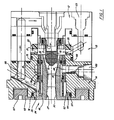
- FIG. 1 shows a cross section of a plasma spray gun 10 incorporating the present invention.
- a gun body 11 is comprised of three components held by screws or bolts (not shown) in sandwich construction, namely a rear gun section 12, an intermediate electrical insulator section 13 and a front gun section 14.
- the rear and front gun sections are made of electrically conductive material such as brass, are electrically insulated from each other by section 13, and are connected respectively to the negative and positive terminals of an arc-forming power source (not shown).
- G un body sections 12 and 13 are of generally annular configuration and, assembled as described above in coaxial relationship, coact to define a cylindrical internal cavity 18 within which are disposed, also in coaxial relationship, a nozzle assembly 24 and an elongate, generally cylindrical cathode member 15.
- Cathode member 15 is constructed of copper, except for a tungsten tip 16, and is mounted in electrical contact with the rear gun section 12, it is held in place with a threaded nut 17.
- cavity 18 terminates in an annular region 19 coaxially disposed about cathode member 15 and adjoining the rearward end of nozzle assembly 24.
- a gas distribution ring 20 is positioned in annular region 19 and has one or more holes 21, preferably two holes as in Fig. 1, which extend radially or have a tangential component for dispersing plasma-forming gas into annular region 19.
- Plasma-forming gas is introduced into the holes 21 via an annular groove 22 encircling the distribution ring 20, the groove 22 in turn being fed gas from gas inlet conduit 23 connected to a gas source (not shown).
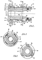
- Nozzle assembly 24 shown per se in Fig. 2, consists of a tubular anode nozzle member 2Wand a coaxial jacket 36 1 the assembly is a close fit in the cylindrical cavity 18 of the gun body and is insertable and removable from the front of gun 10.
- the nozzle assembly 24 is positioned coaxially within front section 14 of the gun body with O-ring seals 74, 75 and 76 (Fig. 1) disposed in respective grooves 59, 61 and 62 (Fig. 2).
- Nozzle member 27, preferably formed of copper, has a radial flange 35 on its forward end portion.
- the interior bore of nozzle member 27 is coaxial with cathode member 15 (Fig. 1) and has a mid-portion 28 preferably of constant diameter.
- the forward position 30 of the bore may also be of constant diameter equal to the mid-portion 28 or may diverge in the forward direction as shown in Figs. 1 and 2.
- the rear portion 29 of the bore diverges rearwardly and cooperates with cathode member 15 to sustain an arc in plasma-forming gas flowing through the nozzle member.
- the operative relative dimensions and spacing of the bore and electrode member for proper plasma gun operation are well known in the art.
- the nozzle member 27 has a generally cylindrical middle portion 31 having an exteriority 32 coaxial with the bore, and has a rear portion 33 having a cylindrical outer surface 34 located generally radially outward from the inlet (rearward) end 29.
- a jacket 36 is positioned to generally surround the nozzle member 27, except for the flange 35, in a predetermined coaxial position.
- the jacket is of generally hollow configuration with a forward inside surface 38 cooperating with the cylindrical middle portion 31 of the nozzle member 27 to define an annular passage 39 for coolant.
- the cylindrical opening 37 and the cylindrical middle portion 31 of the nozzle member 27 are of uniform diameters, forming an annular channel of uniform height preferably in the range of 0.76 mm to 1.27 mm (.030 to .050 inches), for example 1.02 mm (.040 inches), for the purposes of high coolant velocity and efficient cooling as given in U.S. Patent No. 4,430,546.
- jacket 36 has an inner surface 40 cooperative with a cylindrical outer surface 34 of the rear portion 33 of the nozzle member 27 permitting the jacket to slidingly fit concentrically over the rear portion 33 of the nozzle member 27; thus the nozzle member is removable and replaceable from the jacket forward with respect to the jacket.
- the nozzle member is retained by the flange 35 from passing rearward of its normal position in the jacket.
- a rear portal section 47 of jacket 36 contains a plurality of arcuate coolant ports 48 (3 are shown as appears in Fig. 4) equiangularly spaced about the circumference of the jacket.
- the ports are formed and separated by a like plurality of longitudinal struts or ribs 53 similarly spaced about the circumference of the jacket and extending between and integrating the rear portal section with the remainder of the jacket.
- Each of the ports 48 is in direct flow communication with annular coolant passage 39.
- the nozzle flange 35 has a rearward-facing surface 41 coterminating with and extending radially outward from the exteriority 32.
- the forwardly facing end of jacket 36 has a plurality of equiangularly spaced projections 45 which engage the rearwardly-facing surface 41 of flange 35, limiting the rearward movement of nozzle member 27 into jacket 36 when the nozzle member is inserted into the jacket, thus establishing the relative axial positions of the members when assembled.
- the spaces between projections 45 define arcuate coolant ports 48 symmetrically spaced about the longitudinal axis of jacket 36 as best appears in Fig. 3.
- projections 45 are four in number, defining four ports 48, as shown.
- a first seal to retain coolant is provided between the rear portion of the nozzle and the rear section of the jacket, capable of detachment for disassembling the nozzle assembly into its main components, the nozzle and jacket.
- the cylindrical outer surface 34 of the rear portion of the nozzle member 27 has an annular groove 54 therein with a standard 0-ring seal 55 of rubber or the like.
- the cylindrical outer surface 34 should be of uniform diameter and generally the annular groove 54 should be in a maximum diameter section of the cylindrical outer surface.
- the surface 34 has a radius larger than the radius of the cylindrical middle portion 31 of the nozzle member by an amount that is slightly less than the desired width (radial dimension) of annular passage 39, being less only by an amount required for sliding clearance of jacket 36 over the nozzle member, that amount being taken up by the compressed 0- ring.
- the radial dimension of annular passage 39 should be between 0.76 mm and 1.27 mm (0.030 inches and 0.050 inches).
- radial flange 35 is formed with an integral circumferential rim 77 extending radially outward and axially rearward from the flange.
- Rim 77 has an outer circumferential surface 58 and an inner circumferential surface 56, the outer surface 58 containing annular groove 59 accommodating an O-ring seal 74, as previously mentioned (Fig. 1).
- Rim 77 and seal 74 coact with cylindrical cavity 18 of gun body 11 to position nozzle member 27 and seal against leakage of the coolant.
- the rearward-facing radial surface 41 of flange 35 is bounded outwardly by the cylindrical surface 56 at a diameter approximately the same as or greater than the outside diameter of surface 52 of the jacket 36.
- Cylindrical surface 56 preferably extends rearward a distance between approximately half of and equal to the radial separation between the cylindrical middle portion 31 of the nozzle member 27 and the inward-facing surface 56 that the rearward-facing inner surface 41 and the inward facing surface 56 cooperate to form an annular channel j63 for the coolant.
- the rearward-facing outer wall 57 coterminates with and extends radially outward from the cylindrical wall 56 to coterminate with the outward-facing surface 58 of the rim.
- this annular channel 63 has the same outer diameter as the section of the inner surface 64 of the cylindrical cavity 18 of the gun body 11 that extends rearward from the flange 35, thus creating a rearward extension of annular channel 63 for the coolant.
- coolant such as water under pressure from a source (not shown) flows via an inlet channel 65 through the first set of coolant ports 48, along the annular passage 39 to cool the nozzle member 27, out the second set of coolant ports 46, thence through the annular channel 63 and out an exit channel 66. It then is routed to cool the cathode member 15 in the standard manner before it exits the gun.
- annular shoulder 69 on the outer surface of jacket 36 adjacent its inner (rearward) end seats adjacent a complementary shoulder on the inner surface of body section 14 when the nozzle assembly is in place.
- a retainer ring 67 making a threaded joint 68 on the front of gun section 14 holds the nozzle assembly in abutment with shoulder .69.
- Jacket 36 may be made of any convenient material such as brass but is preferably made of electrically insulating material such as a machinable ceramic or a plastic.
- An insulating jacket prevents cross arcing to the gun body should the wall of the nozzle member 27 fail. It also has been found that an insulating jacket in the nozzle assembly, combined with electrical contact of the anode/nozzle only through flange 35 results in a desirably higher voltage such as 11 volts during operation. The benefits of higher voltage are further improvement in nozzle life as well as increased electrical efficiency of the arc. It is speculated that electrical contact at the flange directs the current toward the forward part of the nozzle member so as to encourage a longer arc, reflected as higher voltage.
- the nozzle assembly according to the invention yields a structure for efficiently cooling the nozzle giving it longer life, while providing a convenient means for removing and replacing the nozzle in a plasma spray gun for routine maintenance or when the nozzle becomes excessively eroded from the arc.
- the assembly may be removed from the gun body as a unit, and the jacket 36 readily removed from the nozzle member 27, which is then replaced and the procedure reversed. Alternatively, the jacket may remain in place in the gun body and the nozzle alone removed and replaced. Either method provides a low cost gun construction and economical maintenance. Also, the ease of replacement makes it feasible to interchange nozzle members having different bore dimensions according to requirements for gun operation, while utilizing the same jacket. All nozzle members will have the same external dimensions.
- nozzle wall thickness between the bore and the exteriority of the middle section should be in the range of 1.27 mm to 4.45 mm (.050 to .175 inches) but may vary from this range in the region of diverging inlet and exit ends.
- a preferable nozzle member with a 5.54 mm (.218 inch) diameter bore has a wall thickness between 1.73 mm and 3.58 mm (.068 and .141 inches).
- the nozzle assembly of the present invention is especially suited for a low cost gun, particularly for operation at low to medium power levels, providing simplified construction and easier replacement of nozzle members. Simultaneously there is provided longer nozzle life, improved efficiency, reliable operation and lower cost maintenance.
Landscapes
- Physics & Mathematics (AREA)
- Engineering & Computer Science (AREA)
- Plasma & Fusion (AREA)
- Spectroscopy & Molecular Physics (AREA)
- Electromagnetism (AREA)
- Nozzles (AREA)
- Plasma Technology (AREA)
Applications Claiming Priority (2)
| Application Number | Priority Date | Filing Date | Title |
|---|---|---|---|
| US646734 | 1984-09-04 | ||
| US06/646,734 US4688722A (en) | 1984-09-04 | 1984-09-04 | Nozzle assembly for plasma spray gun |
Publications (3)
| Publication Number | Publication Date |
|---|---|
| EP0173902A2 true EP0173902A2 (fr) | 1986-03-12 |
| EP0173902A3 EP0173902A3 (en) | 1986-12-03 |
| EP0173902B1 EP0173902B1 (fr) | 1990-07-25 |
Family
ID=24594252
Family Applications (1)
| Application Number | Title | Priority Date | Filing Date |
|---|---|---|---|
| EP85110280A Expired EP0173902B1 (fr) | 1984-09-04 | 1985-08-16 | Tuyère pour un pistolet de pulvérisation à plasma |
Country Status (6)
| Country | Link |
|---|---|
| US (1) | US4688722A (fr) |
| EP (1) | EP0173902B1 (fr) |
| JP (1) | JPS6168156A (fr) |
| BR (1) | BR8504242A (fr) |
| CA (1) | CA1246336A (fr) |
| DE (1) | DE3578844D1 (fr) |
Cited By (5)
| Publication number | Priority date | Publication date | Assignee | Title |
|---|---|---|---|---|
| EP0244773A3 (en) * | 1986-05-06 | 1988-01-20 | The Perkin-Elmer Corporation | Gas distribution ring for plasma gun |
| EP0422036A4 (en) * | 1988-05-13 | 1991-10-23 | Applied Polymer Systems, Inc. | Apparatus and method for applying plasma flame sprayed polymers |
| FR2735710A1 (fr) * | 1995-06-23 | 1996-12-27 | Soudure Autogene Francaise | Tete de torche a plasma et torche a plasma la comportant |
| WO2016065736A1 (fr) * | 2014-10-30 | 2016-05-06 | 周开根 | Torche à plasma pour une utilisation de gazéification ou de pyrolyse |
| CN114798211A (zh) * | 2022-04-15 | 2022-07-29 | 厦门盛骅自动化设备有限公司 | 一种长寿命多功能喷枪 |
Families Citing this family (24)
| Publication number | Priority date | Publication date | Assignee | Title |
|---|---|---|---|---|
| US4865252A (en) * | 1988-05-11 | 1989-09-12 | The Perkin-Elmer Corporation | High velocity powder thermal spray gun and method |
| US4964568A (en) * | 1989-01-17 | 1990-10-23 | The Perkin-Elmer Corporation | Shrouded thermal spray gun and method |
| US5186621A (en) * | 1990-03-28 | 1993-02-16 | The Texas A & M University System | Chimney holder and injection tube mount for use in atomic absorption and plasma spectroscopy |
| FR2698301B1 (fr) * | 1992-11-20 | 1994-12-23 | Soudure Autogene Francaise | Torche de coupage plasma. |
| US5285967A (en) * | 1992-12-28 | 1994-02-15 | The Weidman Company, Inc. | High velocity thermal spray gun for spraying plastic coatings |
| DE4446015C2 (de) * | 1994-12-22 | 2002-04-11 | Tbi Ind Gmbh & Co Kg | Gasdüse für Schutzgaslichtbogenschweiß- und Schneidbrenner |
| US5624586A (en) * | 1995-01-04 | 1997-04-29 | Hypertherm, Inc. | Alignment device and method for a plasma arc torch system |
| US5664487A (en) * | 1996-09-19 | 1997-09-09 | Tetra Laval Holdings & Finance Sa | Sanitary filling nozzle mount |
| US6130399A (en) * | 1998-07-20 | 2000-10-10 | Hypertherm, Inc. | Electrode for a plasma arc torch having an improved insert configuration |
| RS49706B (sr) * | 2000-02-24 | 2007-12-31 | Miroljub Vilotijević | Jednosmerni lučni plazma generator sa ulaznom volt- amperskom karakteristikom |
| US6845929B2 (en) * | 2002-03-22 | 2005-01-25 | Ali Dolatabadi | High efficiency nozzle for thermal spray of high quality, low oxide content coatings |
| US7216814B2 (en) * | 2003-10-09 | 2007-05-15 | Xiom Corp. | Apparatus for thermal spray coating |
| US7959983B1 (en) | 2003-10-21 | 2011-06-14 | Farrar Lawrence C | Thermal spray formation of polymer compositions |
| US9099074B1 (en) | 2003-10-21 | 2015-08-04 | Peter A. Lucon | Custom tunable acoustic insulation |
| US20060124767A1 (en) * | 2004-12-13 | 2006-06-15 | Kwan-Ten Enterprise Co., Ltd. | Leakage proof device for a sprinkler nozzle |
| CA2527764C (fr) * | 2005-02-11 | 2014-03-25 | Suelzer Metco Ag | Dispositif de projection a chaud |
| US7759599B2 (en) * | 2005-04-29 | 2010-07-20 | Sulzer Metco (Us), Inc. | Interchangeable plasma nozzle interface |
| USD545851S1 (en) | 2006-03-30 | 2007-07-03 | Dave Hawley | Plasma gun nozzle holder |
| US7993131B2 (en) * | 2007-08-28 | 2011-08-09 | Conocophillips Company | Burner nozzle |
| USD674421S1 (en) * | 2011-01-18 | 2013-01-15 | Hotset Heizpatronen U. Zubehoer Gmbh | Core nozzle |
| WO2013112178A1 (fr) * | 2012-01-27 | 2013-08-01 | Sulzer Metco (Us), Inc. | Pistolet de pulvérisation thermique par pointe de buse amovible et procédé de fabrication et d'utilisation de celui-ci |
| EP2848098B1 (fr) * | 2012-05-10 | 2022-07-06 | Oerlikon Metco (US) Inc. | Interface cathodique échangeable pour un pistolet spray à plasma et procédé pour faire ce pistolet avec cette |
| CN105307372A (zh) * | 2014-06-04 | 2016-02-03 | 成都真火科技有限公司 | 一种电弧通道冷却结构 |
| EP3888425A4 (fr) * | 2018-11-30 | 2023-01-25 | Oerlikon Metco (US) Inc. | Électrode pour un pistolet à plasma |
Family Cites Families (11)
| Publication number | Priority date | Publication date | Assignee | Title |
|---|---|---|---|---|
| US2960594A (en) * | 1958-06-30 | 1960-11-15 | Plasma Flame Corp | Plasma flame generator |
| US3106633A (en) * | 1961-04-21 | 1963-10-08 | Union Carbide Corp | Arc torch device |
| US3106631A (en) * | 1961-04-21 | 1963-10-08 | Union Carbide Corp | Arc torch device |
| US3145287A (en) * | 1961-07-14 | 1964-08-18 | Metco Inc | Plasma flame generator and spray gun |
| US3112072A (en) * | 1962-06-26 | 1963-11-26 | Malone Joseph | Striping attachment for metallizing spray gun |
| US3756511A (en) * | 1971-02-02 | 1973-09-04 | Kogyo Kaihatsu Kenyusho | Nozzle and torch for plasma jet |
| US4169560A (en) * | 1975-03-29 | 1979-10-02 | Elektrostatische Spritz-- und Beflockungsgesellschaft G.F. Vohringer GmbH | Electrostatic spray gun for powdered material |
| US4127760A (en) * | 1975-06-09 | 1978-11-28 | Geotel, Inc. | Electrical plasma jet torch and electrode therefor |
| US4430546A (en) * | 1981-08-14 | 1984-02-07 | Metco, Inc. | Plasma spray gun nozzle |
| US4445021A (en) * | 1981-08-14 | 1984-04-24 | Metco, Inc. | Heavy duty plasma spray gun |
| US4549065A (en) * | 1983-01-21 | 1985-10-22 | Technology Application Services Corporation | Plasma generator and method |
-
1984
- 1984-09-04 US US06/646,734 patent/US4688722A/en not_active Expired - Fee Related
-
1985
- 1985-08-16 EP EP85110280A patent/EP0173902B1/fr not_active Expired
- 1985-08-16 DE DE8585110280T patent/DE3578844D1/de not_active Expired - Lifetime
- 1985-08-26 CA CA000489379A patent/CA1246336A/fr not_active Expired
- 1985-09-03 BR BR8504242A patent/BR8504242A/pt not_active IP Right Cessation
- 1985-09-04 JP JP60194023A patent/JPS6168156A/ja active Pending
Cited By (7)
| Publication number | Priority date | Publication date | Assignee | Title |
|---|---|---|---|---|
| EP0244773A3 (en) * | 1986-05-06 | 1988-01-20 | The Perkin-Elmer Corporation | Gas distribution ring for plasma gun |
| EP0422036A4 (en) * | 1988-05-13 | 1991-10-23 | Applied Polymer Systems, Inc. | Apparatus and method for applying plasma flame sprayed polymers |
| FR2735710A1 (fr) * | 1995-06-23 | 1996-12-27 | Soudure Autogene Francaise | Tete de torche a plasma et torche a plasma la comportant |
| EP0750449A1 (fr) * | 1995-06-23 | 1996-12-27 | La Soudure Autogene Francaise | Tête de torche à plasma et torche à plasma la comportant |
| US5736708A (en) * | 1995-06-23 | 1998-04-07 | La Soudure Autogene Francaise | Plasma torch head with nozzle providing an improved cut and plasma torch including the same |
| WO2016065736A1 (fr) * | 2014-10-30 | 2016-05-06 | 周开根 | Torche à plasma pour une utilisation de gazéification ou de pyrolyse |
| CN114798211A (zh) * | 2022-04-15 | 2022-07-29 | 厦门盛骅自动化设备有限公司 | 一种长寿命多功能喷枪 |
Also Published As
| Publication number | Publication date |
|---|---|
| BR8504242A (pt) | 1986-07-01 |
| DE3578844D1 (de) | 1990-08-30 |
| CA1246336A (fr) | 1988-12-13 |
| JPS6168156A (ja) | 1986-04-08 |
| EP0173902B1 (fr) | 1990-07-25 |
| EP0173902A3 (en) | 1986-12-03 |
| US4688722A (en) | 1987-08-25 |
Similar Documents
| Publication | Publication Date | Title |
|---|---|---|
| US4688722A (en) | Nozzle assembly for plasma spray gun | |
| US5362939A (en) | Convertible plasma arc torch and method of use | |
| EP1503879B1 (fr) | Cartouche avec consommables ; torche a arc plasma avec une telle cartouche | |
| CA2826791C (fr) | Pointe de decoupe au plasma a passages de refroidissement avances | |
| EP1621052B1 (fr) | Procede et dispositif d'alignement des composants d'une torche au plasma d'arc | |
| EP1802179B1 (fr) | Torche à plasma d'arc, et procédés de montage et démontage d'une torche à plasma d'arc | |
| US4506136A (en) | Plasma spray gun having a gas vortex producing nozzle | |
| US4127760A (en) | Electrical plasma jet torch and electrode therefor | |
| US7132619B2 (en) | Plasma arc torch electrode | |
| EP0072408B1 (fr) | Buse pour pistolet de pulvérisation par arc électrique et procédé de déionisation du liquide de refroidissement | |
| SU676147A3 (ru) | Плазменна горелка дл напылени порошкообразных материалов | |
| US4282418A (en) | Plasma torch for micro-plasma welding | |
| US4587397A (en) | Plasma arc torch | |
| EP0072409B1 (fr) | Buse pour un pistolet à plasma | |
| EP0217399A2 (fr) | Corps de buse pour torche à plasma | |
| JPH04355100A (ja) | 高エンタルピープラズマトーチ | |
| US6080955A (en) | Plasma producer with a holder | |
| KR20040084431A (ko) | 공기 플라즈마 토오치 |
Legal Events
| Date | Code | Title | Description |
|---|---|---|---|
| PUAI | Public reference made under article 153(3) epc to a published international application that has entered the european phase |
Free format text: ORIGINAL CODE: 0009012 |
|
| AK | Designated contracting states |
Kind code of ref document: A2 Designated state(s): CH DE FR GB IT LI |
|
| RAP1 | Party data changed (applicant data changed or rights of an application transferred) |
Owner name: THE PERKIN-ELMER CORPORATION |
|
| PUAL | Search report despatched |
Free format text: ORIGINAL CODE: 0009013 |
|
| AK | Designated contracting states |
Kind code of ref document: A3 Designated state(s): CH DE FR GB IT LI |
|
| 17P | Request for examination filed |
Effective date: 19870601 |
|
| 17Q | First examination report despatched |
Effective date: 19881027 |
|
| GRAA | (expected) grant |
Free format text: ORIGINAL CODE: 0009210 |
|
| AK | Designated contracting states |
Kind code of ref document: B1 Designated state(s): CH DE FR GB IT LI |
|
| ITF | It: translation for a ep patent filed | ||
| REF | Corresponds to: |
Ref document number: 3578844 Country of ref document: DE Date of ref document: 19900830 |
|
| ET | Fr: translation filed | ||
| PLBE | No opposition filed within time limit |
Free format text: ORIGINAL CODE: 0009261 |
|
| STAA | Information on the status of an ep patent application or granted ep patent |
Free format text: STATUS: NO OPPOSITION FILED WITHIN TIME LIMIT |
|
| 26N | No opposition filed | ||
| ITTA | It: last paid annual fee | ||
| PGFP | Annual fee paid to national office [announced via postgrant information from national office to epo] |
Ref country code: FR Payment date: 19940712 Year of fee payment: 10 |
|
| PGFP | Annual fee paid to national office [announced via postgrant information from national office to epo] |
Ref country code: CH Payment date: 19940715 Year of fee payment: 10 |
|
| PGFP | Annual fee paid to national office [announced via postgrant information from national office to epo] |
Ref country code: DE Payment date: 19940725 Year of fee payment: 10 |
|
| PGFP | Annual fee paid to national office [announced via postgrant information from national office to epo] |
Ref country code: GB Payment date: 19940728 Year of fee payment: 10 |
|
| PG25 | Lapsed in a contracting state [announced via postgrant information from national office to epo] |
Ref country code: GB Effective date: 19950816 |
|
| PG25 | Lapsed in a contracting state [announced via postgrant information from national office to epo] |
Ref country code: LI Effective date: 19950831 Ref country code: CH Effective date: 19950831 |
|
| REG | Reference to a national code |
Ref country code: CH Ref legal event code: PL |
|
| GBPC | Gb: european patent ceased through non-payment of renewal fee |
Effective date: 19950816 |
|
| PG25 | Lapsed in a contracting state [announced via postgrant information from national office to epo] |
Ref country code: FR Effective date: 19960430 |
|
| PG25 | Lapsed in a contracting state [announced via postgrant information from national office to epo] |
Ref country code: DE Effective date: 19960501 |
|
| REG | Reference to a national code |
Ref country code: FR Ref legal event code: ST |