EP0173779B1 - Luggage case and an assembly for mounting rotational ground engaging means thereto - Google Patents
Luggage case and an assembly for mounting rotational ground engaging means thereto Download PDFInfo
- Publication number
- EP0173779B1 EP0173779B1 EP84306082A EP84306082A EP0173779B1 EP 0173779 B1 EP0173779 B1 EP 0173779B1 EP 84306082 A EP84306082 A EP 84306082A EP 84306082 A EP84306082 A EP 84306082A EP 0173779 B1 EP0173779 B1 EP 0173779B1
- Authority
- EP
- European Patent Office
- Prior art keywords
- wheel
- shock absorbing
- shell
- axle
- case
- Prior art date
- Legal status (The legal status is an assumption and is not a legal conclusion. Google has not performed a legal analysis and makes no representation as to the accuracy of the status listed.)
- Expired - Lifetime
Links
- 230000035939 shock Effects 0.000 claims description 64
- 239000013536 elastomeric material Substances 0.000 claims description 7
- 229920001875 Ebonite Polymers 0.000 abstract description 4
- 229920001971 elastomer Polymers 0.000 description 13
- 239000005060 rubber Substances 0.000 description 13
- 239000000853 adhesive Substances 0.000 description 2
- 230000001070 adhesive effect Effects 0.000 description 2
- 235000004443 Ricinus communis Nutrition 0.000 description 1
- 239000006096 absorbing agent Substances 0.000 description 1
- 239000007767 bonding agent Substances 0.000 description 1
- 238000010276 construction Methods 0.000 description 1
- 239000000463 material Substances 0.000 description 1
- 239000002184 metal Substances 0.000 description 1
- 238000000034 method Methods 0.000 description 1
- 230000002093 peripheral effect Effects 0.000 description 1
- 239000004033 plastic Substances 0.000 description 1
- 229920003023 plastic Polymers 0.000 description 1
- 238000005096 rolling process Methods 0.000 description 1
- 238000004073 vulcanization Methods 0.000 description 1
Images
Classifications
-
- A—HUMAN NECESSITIES
- A45—HAND OR TRAVELLING ARTICLES
- A45C—PURSES; LUGGAGE; HAND CARRIED BAGS
- A45C5/00—Rigid or semi-rigid luggage
-
- A—HUMAN NECESSITIES
- A45—HAND OR TRAVELLING ARTICLES
- A45C—PURSES; LUGGAGE; HAND CARRIED BAGS
- A45C5/00—Rigid or semi-rigid luggage
- A45C5/14—Rigid or semi-rigid luggage with built-in rolling means
-
- A—HUMAN NECESSITIES
- A45—HAND OR TRAVELLING ARTICLES
- A45C—PURSES; LUGGAGE; HAND CARRIED BAGS
- A45C13/00—Details; Accessories
Definitions
- the present invention relates to luggage cases of the type that have wheel rollers, casters or other rotational ground engaging means projecting from their outer shell such that the case can be rolled on the ground engaging means for ease of transport.
- a suitcase of this type is shown in GB-A-2030966A.
- a wheel housing is formed by walls integrally moulded with the shell of the suitcase. The ends of the axle of the wheel pass through and are supported by the walls.
- a disadvantage of the known arrangements is that the mounting of the wheels rollers or casters to the suitcase is rigid. When the suitcase is wheeled over a bumpy surface vibrations are transmitted from the rotational ground engaging means to the case resulting in noisy running and a liability for the mountings for the ground engaging means to be damaged.
- DE-A-3202007 discloses an assembly for mounting rotational ground engaging means to a case comprising: an axle; ground engaging means mounted for rotation on the axle; and resilient shock absorbing means, said shock absorbing means being secured to the case on the one hand and to the axle on the other whereby the shock absorbing means absorbs the shock from the ground engaging means.
- the shock absorbing means is in the form of a specially shaped stirrup like member which extends to either side of and above the ground engaging means.
- US-A-2272270 also describes an arrangement for mounting wheels.
- the wheels are of the castor type with the axle supported at both ends from mounting legs.
- Shock absorbing cushioning members are disposed between each mounting leg and a plate which supports the adjacent end of the axle.
- the cushioning members are laterally outside the overall width of the wheel making the overall assembly unsuitable for use in confined spaces. Tilting of the axle to absorb shocks is restricted because it is supported at both ends.
- an assembly for mounting rotational ground engaging means to a case comprising: an axle; ground engaging means mounted for rotation on the axle; mounting means for securing the axles to the case, and resilient shock absorbing means, said shock absorbing means being secured directly to the mounting means on the one hand and directly to the axle on the other whereby in use with the assembly mounted on a case the shock absorbing means absorbs the shock from the ground engaging means known from US-A-2272270, characterised in that the rotational ground engaging means are cantilevered and at least a portion of the resilient shock absorbing means is positioned laterally within the overall width of the ground engaging means.
- the present invention permits the construction of a simple compact wheel assembly having relatively few parts.
- the resilient shock absorbing means comprises a block of elastomeric material.
- a rubber of Shore hardness 55 to 60 Shore A has been found suitable. Rubbers of different hardness will be found suitable for other cases depending on the size of the case and load it is likely to have to carry. The smaller the case and load, the lower the hardness may be.
- the inner end of the axle may be widened to provide an extended mounting surface to which the resilient shock absorbing means is fixed.
- the axle is secured via its resilient shock absorbing means to a mounting plate which is fixed directly to the case.
- vulcanisation is a convenient way of ensuring that a good bonding is achieved between an elastomeric shock absorbing means and the mounting means on the one hand and the axle on the other.
- Other suitable means for securing the shock absorbing means may be used, for example adhesive or screws.
- a luggage case comprising a shell, a wheel, an axle for rotatably mounting the wheel, resilient shock absorbing means secured directly to said axle, and means for mounting said shock absorbing means directly to an outer surface of said shell, known from US-A-2272270, characterised in that the wheel is cantilevered and at least a portion of said shock absorbing means is positioned laterally within the overall axial width of the wheel.
- a luggage case comprising a shell having recesses located at a corner, wheels rotatably mounted to the shell, the wheels being mounted at the corner of the shell in the recess in the shell on axles passing through the centre of each wheel, and resilient shock absorbing means secured to the axle and the shell, a portion of the shell overhanging the ground engaging portion of said wheel, known from US-A-2272270, characterised in that each axle is a cantilever stub axle and has a flange positioned laterally inward from the innermost edge of each said wheel, the resilient shock absorbing member is attached to a surface of the flange, at least a portion of said resilient shock absorbing member being positioned laterally inward of the inner edge of the wheel and within the overall axial width of the wheel, the resilient shock absorbing member is fastened in turn to a mounting plate for securing the wheel and axle to the shell, and the spacing between the shell and the ground engaging portion of the wheel is less than a maximum def
- a suitcase 10 consists of a rigid shell 11 formed in two halves for example, of plastics material.
- the case has a carrying handle 12.
- the case is also provided with a pair of wheels 13 at one of its lower corners 14 and a hinged steering handle 15. Normally the steering handle is folded flat against the wall of the suitcase but it can be hinged away from the case for steering the case when the case is being rolled on the wheels 13 at the lower corner.
- the suitcase is provided, on either side at the corner 14, with a recess 16 which accommodates a respective one of the wheels 13.
- Each wheel assembly consists of a wheel hub 17 with a tyre 18 at its rim.
- the wheel hub 17 includes an outer rim 17a which, along with tyre 18, defines the overall axial width of wheel.
- Wheel hub 17 further includes a central axle sleeve 17b through which central axial opening 20 passes.
- the axle sleeve 17b terminates inwardly of the inner edge of the outer rim 17a.
- the wheel is rotatably mounted on a cantilever stub shaft 19 which passes through central axial opening 20 in the wheel.
- the stub shaft has a circular flange 21 at its inner end adjacent the axle sleeve 17b and the wheel is held captive on the shaft by means of a clip 22 on the outer end of the shaft.
- the stub shaft is secured by means of its flange 21 to a resilient shock absorbing means, in this embodiment a disc 23 of hard rubber.
- the disc in turn is secured to a generally sector shaped mounting plate 24.
- the flange 21 is positioned laterally inward from the inner edge of the wheel, more specifically from the inner edge of the outer rim 17a.
- at least a portion of the disc 23 is positioned laterally within the overall axial width of the wheel.
- the wheel assembly is secured in the recess to the wall of the suitcase for example, by means of rivets or screws 25 which pass through the mounting plate 24 and a portion of the suitcase wall 26.
- the mounting plate 24 and the stub shaft 19 may be made of metal.
- the rubber shock absorbing member is preferably secured to the stub shaft and the mounting plate by vulcanising.
- the stub shaft and mounting plate are degreased and coated with a bonding agent.
- the parts are then placed in a mould and vulcanised. We have found that this technique produces a strong bond between the rubber disc 23 and the stub shaft and mounting plate.
- the parts may be secured to the rubber shock absorbing member with a suitable adhesive or using screws which pass through the flange on the stub shaft and through the mounting plate into the rubber.
- the rubber is a hard rubber having a Shore hardness of between 55 and 60 Shore A.
- the rubber must not bend too much otherwise the suitcase would be difficult to wheel because the wheels would rub against the wait of the case.
- the rubber must be sufficiently soft to absorb shocks.
- the portion of the suitcase wall 28 which overhangs the wheels in the recess may be spaced sufficiently close to the rim of the wheel that if the suitcase is dropped on the wheels the deflection of the wheels about the resilient shock absorbing disc 21 causes the periphery of the wheel to make contact with the wall 28.
- the suitcase wall may be designed to limit the maximum deflection of the wheel on its mounting, transferring some of the shock to the suitcase directly through the overhanging portion and preventing severe shocks causing damage to the wheel mounting.
- the rubber disc must be sufficiently hard to prevent the normal deflection of the stub shaft on its mounting when the suitcase is rolled on the ground from causing the wheel to come into contact with the overhanging portion 28 of the wall.
- the rubber disc 23 is 3 mm thick and 25 mm in diameter, although other suitable dimensions will work.
- the resilient shock absorbing means formed by the rubber disc 23 absorbs vibration of the wheels and reduces the amount of vibration transmitted to the suitcase. This causes the amount of noise generated by the wheels to be greatly reduced and makes the suitcase more comfortable to roll.
- the resilient mounting also reduces the shocks on the stub shaft and the case mounting. In this way the stub shaft and mounting are less likely to be damaged.
- the axles passes through the wall of the suitcase it is necessary to reinforce the suitcase in the region of the wheel mounting in order to prevent damage in use. In the embodiment described above the axle does not pass through the suitcase wall and therefore this problem does not arise.
- the shock absorbing mounting also tends to damp any swaying movement of the case which may start as the case is being rolled along, and thus prevent the suitcase getting out of control.
- the resilient shock absorbing means in this embodiment comprises a block of hard rubber 123 has portions of two different diameters.
- the larger diameter portion is secured to the mounting plate 124 which is cup-shaped having a peripheral flange 130 which extends around the periphery of the larger diameter portion.
- the stub shaft 119 has a cup-shaped flange 121 which surrounds the smaller diameter portion
- the shock absorbing rubber block 123 may be secured to the stub shaft and the mounting plate in any of the ways described in relation to the embodiment of Figures 1 to 3.
- the flange 121 is positioned laterally inward from the inward from the inner edge of the wheel so that at least a portion of the resilient shock absorbing means is positioned laterally within the overall width of the wheel.
- the shock absorbing block 223 is disc-shaped with a central opening 231.
- the stub shaft 219 is secured in the opening 231.
- the embodiment is the same as that of Figure 4 with at least a portion of the resilient shock absorbing means being positioned within the maximum width of the wheel.
Landscapes
- Purses, Travelling Bags, Baskets, Or Suitcases (AREA)
- Handcart (AREA)
- Air Bags (AREA)
- Warehouses Or Storage Devices (AREA)
- Investigating, Analyzing Materials By Fluorescence Or Luminescence (AREA)
- Crystals, And After-Treatments Of Crystals (AREA)
- Tea And Coffee (AREA)
- Distillation Of Fermentation Liquor, Processing Of Alcohols, Vinegar And Beer (AREA)
- Carriages For Children, Sleds, And Other Hand-Operated Vehicles (AREA)
- Spinning Or Twisting Of Yarns (AREA)
Abstract
Description
- The present invention relates to luggage cases of the type that have wheel rollers, casters or other rotational ground engaging means projecting from their outer shell such that the case can be rolled on the ground engaging means for ease of transport.
- A suitcase of this type is shown in GB-A-2030966A. In this arrangement a wheel housing is formed by walls integrally moulded with the shell of the suitcase. The ends of the axle of the wheel pass through and are supported by the walls.
- An alternative arrangement is shown in GB-A-2116149A in which a wheel axle is secured to a plate which is attached by screws to the shell of the suitcase.
- A disadvantage of the known arrangements is that the mounting of the wheels rollers or casters to the suitcase is rigid. When the suitcase is wheeled over a bumpy surface vibrations are transmitted from the rotational ground engaging means to the case resulting in noisy running and a liability for the mountings for the ground engaging means to be damaged.
- DE-A-3202007 discloses an assembly for mounting rotational ground engaging means to a case comprising:
an axle; ground engaging means mounted for rotation on the axle; and resilient shock absorbing means, said shock absorbing means being secured to the case on the one hand and to the axle on the other whereby the shock absorbing means absorbs the shock from the ground engaging means. The shock absorbing means is in the form of a specially shaped stirrup like member which extends to either side of and above the ground engaging means. - US-A-2272270 also describes an arrangement for mounting wheels. The wheels are of the castor type with the axle supported at both ends from mounting legs. Shock absorbing cushioning members are disposed between each mounting leg and a plate which supports the adjacent end of the axle. The cushioning members are laterally outside the overall width of the wheel making the overall assembly unsuitable for use in confined spaces. Tilting of the axle to absorb shocks is restricted because it is supported at both ends.
- According to the present invention in a first aspect there is provided an assembly for mounting rotational ground engaging means to a case comprising: an axle; ground engaging means mounted for rotation on the axle; mounting means for securing the axles to the case, and resilient shock absorbing means, said shock absorbing means being secured directly to the mounting means on the one hand and directly to the axle on the other whereby in use with the assembly mounted on a case the shock absorbing means absorbs the shock from the ground engaging means known from US-A-2272270, characterised in that the rotational ground engaging means are cantilevered and at least a portion of the resilient shock absorbing means is positioned laterally within the overall width of the ground engaging means.
- With this arrangement vibrations resulting from contact of the ground engaging means with the ground are absorbed before they reach the case. If the case starts to sway the shock absorbers serve to damp the swaying movement. As a result, the case is easier and more convenient to handle when rolling on the ground engaging means, the case is less noisy, and there is less tendency for the mounting to be damaged. The present invention permits the construction of a simple compact wheel assembly having relatively few parts.
- Preferably the resilient shock absorbing means comprises a block of elastomeric material. For one particular design of case a rubber of Shore hardness 55 to 60 Shore A has been found suitable. Rubbers of different hardness will be found suitable for other cases depending on the size of the case and load it is likely to have to carry. The smaller the case and load, the lower the hardness may be.
- The inner end of the axle may be widened to provide an extended mounting surface to which the resilient shock absorbing means is fixed. Preferably the axle is secured via its resilient shock absorbing means to a mounting plate which is fixed directly to the case.
- We have found that vulcanisation is a convenient way of ensuring that a good bonding is achieved between an elastomeric shock absorbing means and the mounting means on the one hand and the axle on the other. Other suitable means for securing the shock absorbing means may be used, for example adhesive or screws.
- According to the present invention in a second aspect, there is provided a luggage case comprising a shell, a wheel, an axle for rotatably mounting the wheel, resilient shock absorbing means secured directly to said axle, and means for mounting said shock absorbing means directly to an outer surface of said shell, known from US-A-2272270, characterised in that the wheel is cantilevered and at least a portion of said shock absorbing means is positioned laterally within the overall axial width of the wheel.
- According to the present invention in a third aspect there is provided a luggage case comprising a shell having recesses located at a corner, wheels rotatably mounted to the shell, the wheels being mounted at the corner of the shell in the recess in the shell on axles passing through the centre of each wheel, and resilient shock absorbing means secured to the axle and the shell, a portion of the shell overhanging the ground engaging portion of said wheel, known from US-A-2272270, characterised in that each axle is a cantilever stub axle and has a flange positioned laterally inward from the innermost edge of each said wheel, the resilient shock absorbing member is attached to a surface of the flange, at least a portion of said resilient shock absorbing member being positioned laterally inward of the inner edge of the wheel and within the overall axial width of the wheel, the resilient shock absorbing member is fastened in turn to a mounting plate for securing the wheel and axle to the shell, and the spacing between the shell and the ground engaging portion of the wheel is less than a maximum deflection of the wheel and axle assembly about the resilient shock absorbing means, whereby the wheel makes contact with the overhanging portion of the shell when the wheel is subjected to severe shock.
- Embodiments of the invention will now be described by way of example with reference to the accompanying drawings in which:
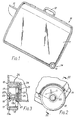
- Figure 1 is a side elevation of a suitcase fitted with a wheel assembly according to the invention;
- Figure 2 is an enlarged detail of the wheel assembly of the case of Figure 1;
- Figure 3 is a cross section on the lines 3-3 of Figure 2;
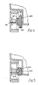
- Figure 4 is a cross section through a modified wheel assembly according to the invention; and
- Figure 5 is a cross section through another wheel assembly according to the invention.
- Referring to the drawings, a suitcase 10 consists of a
rigid shell 11 formed in two halves for example, of plastics material. The case has acarrying handle 12. - For ease of transport when heavily loaded, the case is also provided with a pair of
wheels 13 at one of itslower corners 14 and a hingedsteering handle 15. Normally the steering handle is folded flat against the wall of the suitcase but it can be hinged away from the case for steering the case when the case is being rolled on thewheels 13 at the lower corner. - The suitcase is provided, on either side at the
corner 14, with arecess 16 which accommodates a respective one of thewheels 13. - Each wheel assembly consists of a
wheel hub 17 with atyre 18 at its rim. Thewheel hub 17 includes anouter rim 17a which, along withtyre 18, defines the overall axial width of wheel.Wheel hub 17 further includes a central axle sleeve 17b through which central axial opening 20 passes. The axle sleeve 17b terminates inwardly of the inner edge of theouter rim 17a. - The wheel is rotatably mounted on a
cantilever stub shaft 19 which passes through centralaxial opening 20 in the wheel. The stub shaft has a circular flange 21 at its inner end adjacent the axle sleeve 17b and the wheel is held captive on the shaft by means of aclip 22 on the outer end of the shaft. - The stub shaft is secured by means of its flange 21 to a resilient shock absorbing means, in this embodiment a
disc 23 of hard rubber. The disc in turn is secured to a generally sector shapedmounting plate 24. The flange 21 is positioned laterally inward from the inner edge of the wheel, more specifically from the inner edge of theouter rim 17a. Thus, at least a portion of thedisc 23 is positioned laterally within the overall axial width of the wheel. - The wheel assembly is secured in the recess to the wall of the suitcase for example, by means of rivets or
screws 25 which pass through themounting plate 24 and a portion of thesuitcase wall 26. - The
mounting plate 24 and thestub shaft 19 may be made of metal. The rubber shock absorbing member is preferably secured to the stub shaft and the mounting plate by vulcanising. The stub shaft and mounting plate are degreased and coated with a bonding agent. The parts are then placed in a mould and vulcanised. We have found that this technique produces a strong bond between therubber disc 23 and the stub shaft and mounting plate. Alternatively the parts may be secured to the rubber shock absorbing member with a suitable adhesive or using screws which pass through the flange on the stub shaft and through the mounting plate into the rubber. - The rubber is a hard rubber having a Shore hardness of between 55 and 60 Shore A. The rubber must not bend too much otherwise the suitcase would be difficult to wheel because the wheels would rub against the wait of the case. On the other hand the rubber must be sufficiently soft to absorb shocks. The portion of the
suitcase wall 28 which overhangs the wheels in the recess may be spaced sufficiently close to the rim of the wheel that if the suitcase is dropped on the wheels the deflection of the wheels about the resilient shock absorbing disc 21 causes the periphery of the wheel to make contact with thewall 28. In this way the suitcase wall may be designed to limit the maximum deflection of the wheel on its mounting, transferring some of the shock to the suitcase directly through the overhanging portion and preventing severe shocks causing damage to the wheel mounting. It will be appreciated that the rubber disc must be sufficiently hard to prevent the normal deflection of the stub shaft on its mounting when the suitcase is rolled on the ground from causing the wheel to come into contact with the overhangingportion 28 of the wall. - In the preferred embodiment the
rubber disc 23 is 3 mm thick and 25 mm in diameter, although other suitable dimensions will work. - When the suitcase fitted with the wheel assembly as described above is rolled on the ground the resilient shock absorbing means formed by the
rubber disc 23 absorbs vibration of the wheels and reduces the amount of vibration transmitted to the suitcase. This causes the amount of noise generated by the wheels to be greatly reduced and makes the suitcase more comfortable to roll. The resilient mounting also reduces the shocks on the stub shaft and the case mounting. In this way the stub shaft and mounting are less likely to be damaged. In suitcases where the axles passes through the wall of the suitcase it is necessary to reinforce the suitcase in the region of the wheel mounting in order to prevent damage in use. In the embodiment described above the axle does not pass through the suitcase wall and therefore this problem does not arise. - The shock absorbing mounting also tends to damp any swaying movement of the case which may start as the case is being rolled along, and thus prevent the suitcase getting out of control.
- Referring now to Figure 4, this shows a modified form of mounting for a cantilever stub shaft. The resilient shock absorbing means in this embodiment comprises a block of
hard rubber 123 has portions of two different diameters. The larger diameter portion is secured to the mountingplate 124 which is cup-shaped having aperipheral flange 130 which extends around the periphery of the larger diameter portion. Thestub shaft 119 has a cup-shapedflange 121 which surrounds the smaller diameter portion The shock absorbingrubber block 123 may be secured to the stub shaft and the mounting plate in any of the ways described in relation to the embodiment of Figures 1 to 3. Here, as in the embodiment of Figures 1 through 3, theflange 121 is positioned laterally inward from the inward from the inner edge of the wheel so that at least a portion of the resilient shock absorbing means is positioned laterally within the overall width of the wheel. - In the embodiment of Figure 5 the
shock absorbing block 223 is disc-shaped with acentral opening 231. Thestub shaft 219 is secured in theopening 231. In other respects the embodiment is the same as that of Figure 4 with at least a portion of the resilient shock absorbing means being positioned within the maximum width of the wheel.
Claims (15)
Priority Applications (16)
| Application Number | Priority Date | Filing Date | Title |
|---|---|---|---|
| AT84306082T ATE59136T1 (en) | 1984-09-06 | 1984-09-06 | CASE AND FLOOR WHEELS MOUNTED TO IT. |
| EP84306082A EP0173779B1 (en) | 1984-09-06 | 1984-09-06 | Luggage case and an assembly for mounting rotational ground engaging means thereto |
| DE8484306082T DE3483786D1 (en) | 1984-09-06 | 1984-09-06 | SUITCASE AND GROUND WHEELS MOUNTED ON IT. |
| IN692/DEL/85A IN165834B (en) | 1984-09-06 | 1985-08-21 | |
| ES1985296545U ES296545Y (en) | 1984-09-06 | 1985-09-05 | SUITCASE PROVIDED WITH A CONTACT DEVICE WITH THE FLOOR MOUNTED ROTATELY ON A SHAFT. |
| CA000490093A CA1249250A (en) | 1984-09-06 | 1985-09-05 | Luggage case and wheel roller or caster assembly therefor |
| BR8506912A BR8506912A (en) | 1984-09-06 | 1985-09-06 | VALISE AND ASSEMBLY OF CASTERS OR ROLLERS FOR THE SAME |
| PCT/EP1985/000482 WO1986001383A1 (en) | 1984-09-06 | 1985-09-06 | Luggage case and wheel roller or caster assembly therefor |
| MX206546A MX163105B (en) | 1984-09-06 | 1985-09-06 | LUGGAGE BAG AND SET OF WHEELS OR SLICES FOR THE SAME |
| JP60504485A JPS62500155A (en) | 1984-09-06 | 1985-09-06 | Bags and wheel roller or caster assemblies therefor |
| US06/867,187 US4707881A (en) | 1984-09-06 | 1985-09-06 | Luggage case and wheel roller or caster assembly therefor |
| KR1019860700240A KR920010708B1 (en) | 1984-09-06 | 1985-09-06 | Travel luggage bag |
| DK206186A DK159043C (en) | 1984-09-06 | 1986-05-05 | BOX WITH WHEELS |
| ES1986296883U ES296883Y (en) | 1984-09-06 | 1986-06-13 | ASSEMBLY FOR THE ASSEMBLY OF ROTATING MEANS OF CONTACT WITH THE FLOOR IN A SUITCASE |
| SG963/92A SG96392G (en) | 1984-09-06 | 1992-09-25 | Luggage case and an assembly for mounting rotational ground engaging means thereto |
| HK988/92A HK98892A (en) | 1984-09-06 | 1992-12-10 | Luggage case and an assembly for mounting rotational ground engaging means thereto |
Applications Claiming Priority (1)
| Application Number | Priority Date | Filing Date | Title |
|---|---|---|---|
| EP84306082A EP0173779B1 (en) | 1984-09-06 | 1984-09-06 | Luggage case and an assembly for mounting rotational ground engaging means thereto |
Publications (2)
| Publication Number | Publication Date |
|---|---|
| EP0173779A1 EP0173779A1 (en) | 1986-03-12 |
| EP0173779B1 true EP0173779B1 (en) | 1990-12-19 |
Family
ID=8192748
Family Applications (1)
| Application Number | Title | Priority Date | Filing Date |
|---|---|---|---|
| EP84306082A Expired - Lifetime EP0173779B1 (en) | 1984-09-06 | 1984-09-06 | Luggage case and an assembly for mounting rotational ground engaging means thereto |
Country Status (15)
| Country | Link |
|---|---|
| US (1) | US4707881A (en) |
| EP (1) | EP0173779B1 (en) |
| JP (1) | JPS62500155A (en) |
| KR (1) | KR920010708B1 (en) |
| AT (1) | ATE59136T1 (en) |
| BR (1) | BR8506912A (en) |
| CA (1) | CA1249250A (en) |
| DE (1) | DE3483786D1 (en) |
| DK (1) | DK159043C (en) |
| ES (2) | ES296545Y (en) |
| HK (1) | HK98892A (en) |
| IN (1) | IN165834B (en) |
| MX (1) | MX163105B (en) |
| SG (1) | SG96392G (en) |
| WO (1) | WO1986001383A1 (en) |
Families Citing this family (19)
| Publication number | Priority date | Publication date | Assignee | Title |
|---|---|---|---|---|
| USD322359S (en) | 1989-02-13 | 1991-12-17 | Carlton International Plc | Case |
| US5197579A (en) * | 1990-03-02 | 1993-03-30 | American Tourister, Inc. | Luggage with pull handle |
| US5048649A (en) * | 1990-03-02 | 1991-09-17 | American Tourister, Inc. | Luggage with pull handle |
| US5181590A (en) * | 1990-03-02 | 1993-01-26 | American Tourister, Inc. | Luggage frame with pull handle |
| US5136751A (en) * | 1991-04-30 | 1992-08-11 | Master Manufacturing Co. | Wheel assembly |
| EP0585488B1 (en) * | 1992-09-03 | 1996-12-11 | Günter Schneider | Suitcase with rollers |
| WO1994015802A1 (en) * | 1992-12-30 | 1994-07-21 | Robert Joseph Reader | Castor support |
| DE9317464U1 (en) * | 1993-11-15 | 1995-03-16 | Liebherr-Hausgeräte GmbH, 88416 Ochsenhausen | Caster |
| US5564805A (en) * | 1994-01-03 | 1996-10-15 | Contico International, Inc. | Storage container with wheels |
| GB2291042A (en) * | 1994-07-05 | 1996-01-17 | Dick Ming Hsieh | Wheel assembly of a luggage |
| US5493755A (en) * | 1994-09-06 | 1996-02-27 | Applied Power Inc. | Shock and vibration isolating caster suspension |
| EP0793925B1 (en) * | 1996-03-08 | 1999-09-15 | Samsonite Corporation | Wheel mounting system for molded luggage case |
| US6193324B1 (en) * | 1999-07-09 | 2001-02-27 | Wen-Chen Chang | Wheel device |
| US6550100B2 (en) | 2001-02-08 | 2003-04-22 | Waxman Industries, Inc. | Caster assembly with multi-position support pieces |
| US6728991B2 (en) | 2002-04-15 | 2004-05-04 | Waxman Industries, Inc. | Caster assembly with sliding side support piece |
| US6748623B1 (en) * | 2002-11-27 | 2004-06-15 | Po-Chuan Tsai | Chair caster |
| US9961974B2 (en) | 2011-11-14 | 2018-05-08 | Samsonite Ip Holdings S.A R.L. | Protective system for luggage |
| USD710614S1 (en) | 2012-08-10 | 2014-08-12 | Samsonite IP Holdings S.ar.l. | Luggage wheel housing |
| US20210016815A1 (en) * | 2019-07-19 | 2021-01-21 | James S. Fleser | Roller cart luggage |
Family Cites Families (13)
| Publication number | Priority date | Publication date | Assignee | Title |
|---|---|---|---|---|
| US1527239A (en) * | 1923-12-13 | 1925-02-24 | George J Vaughan | Supporting and guiding cane |
| US1948476A (en) * | 1930-08-13 | 1934-02-20 | Firestone Tire & Rubber Co | Rubber shock and vibration insulator |
| US1876812A (en) * | 1931-09-03 | 1932-09-13 | Herbert H Wiley | Motor mounting |
| FR859184A (en) * | 1938-08-18 | 1940-12-12 | Vehicle suspension | |
| US2272270A (en) * | 1939-12-15 | 1942-02-10 | Goodrich Co B F | Cushioned mounting for wheels |
| US3163268A (en) * | 1962-08-23 | 1964-12-29 | Leavell Charles | Wheel-equipped suitcase |
| US3433500A (en) * | 1967-08-28 | 1969-03-18 | Roll Rite Corp | Universal caster |
| DE2833330C2 (en) * | 1978-07-29 | 1982-12-23 | Paul Vom Stein & Co, 5632 Wermelskirchen | Castor for trolleys, apparatus, furniture or the like. |
| US4188048A (en) * | 1978-08-02 | 1980-02-12 | Ford Motor Company | Wheel suspension |
| US4229855A (en) * | 1979-02-21 | 1980-10-28 | Rowe Anthony P V | Wheel units |
| DE3202007C1 (en) * | 1982-01-22 | 1983-08-11 | Christoph Dipl.-Ing. 3000 Bern Müller | Resilient bearing part for suitcase rolls |
| FR2521840A1 (en) * | 1982-02-24 | 1983-08-26 | Delsey Soc | CASE ON WHEELS |
| FR2526112A3 (en) * | 1982-05-03 | 1983-11-04 | Caoutchouc Manuf Plastique | Anti-vibration engine mounting - has hollow-section flexible mounting fixed between two support plates |
-
1984
- 1984-09-06 AT AT84306082T patent/ATE59136T1/en not_active IP Right Cessation
- 1984-09-06 DE DE8484306082T patent/DE3483786D1/en not_active Expired - Lifetime
- 1984-09-06 EP EP84306082A patent/EP0173779B1/en not_active Expired - Lifetime
-
1985
- 1985-08-21 IN IN692/DEL/85A patent/IN165834B/en unknown
- 1985-09-05 CA CA000490093A patent/CA1249250A/en not_active Expired
- 1985-09-05 ES ES1985296545U patent/ES296545Y/en not_active Expired
- 1985-09-06 KR KR1019860700240A patent/KR920010708B1/en not_active Expired
- 1985-09-06 US US06/867,187 patent/US4707881A/en not_active Expired - Fee Related
- 1985-09-06 WO PCT/EP1985/000482 patent/WO1986001383A1/en not_active Ceased
- 1985-09-06 MX MX206546A patent/MX163105B/en unknown
- 1985-09-06 BR BR8506912A patent/BR8506912A/en not_active IP Right Cessation
- 1985-09-06 JP JP60504485A patent/JPS62500155A/en active Pending
-
1986
- 1986-05-05 DK DK206186A patent/DK159043C/en not_active IP Right Cessation
- 1986-06-13 ES ES1986296883U patent/ES296883Y/en not_active Expired
-
1992
- 1992-09-25 SG SG963/92A patent/SG96392G/en unknown
- 1992-12-10 HK HK988/92A patent/HK98892A/en unknown
Also Published As
| Publication number | Publication date |
|---|---|
| DE3483786D1 (en) | 1991-01-31 |
| BR8506912A (en) | 1986-12-09 |
| DK159043C (en) | 1991-02-04 |
| EP0173779A1 (en) | 1986-03-12 |
| SG96392G (en) | 1992-12-04 |
| DK206186D0 (en) | 1986-05-05 |
| DK159043B (en) | 1990-08-27 |
| CA1249250A (en) | 1989-01-24 |
| ES296545U (en) | 1988-02-01 |
| HK98892A (en) | 1992-12-18 |
| KR920010708B1 (en) | 1992-12-14 |
| ATE59136T1 (en) | 1991-01-15 |
| KR870700258A (en) | 1987-08-20 |
| ES296545Y (en) | 1989-09-01 |
| IN165834B (en) | 1990-01-20 |
| DK206186A (en) | 1986-05-05 |
| US4707881A (en) | 1987-11-24 |
| ES296883Y (en) | 1988-11-16 |
| MX163105B (en) | 1991-08-26 |
| JPS62500155A (en) | 1987-01-22 |
| ES296883U (en) | 1988-04-01 |
| WO1986001383A1 (en) | 1986-03-13 |
Similar Documents
| Publication | Publication Date | Title |
|---|---|---|
| US4707881A (en) | Luggage case and wheel roller or caster assembly therefor | |
| US4649595A (en) | Resiliently mounted caster having a pivotally mounted inner body member | |
| CN110077184B (en) | Mecanum wheel omnidirectional mobile robot independent suspension structure | |
| US2241686A (en) | Wheel guard | |
| US2878074A (en) | Resilient wheels | |
| US4312096A (en) | Caster assembly | |
| US2272270A (en) | Cushioned mounting for wheels | |
| JP2008307916A (en) | Caster | |
| US5607178A (en) | Rear wheel isolation suspension for floor scrubbers | |
| US3084950A (en) | Shock absorbing wheel mounting assembly | |
| JP2003159905A (en) | Caster | |
| BG101042A (en) | Wheel pair for transport vehicles | |
| JP6251466B2 (en) | Buffer caster | |
| CN212373072U (en) | Damping luggage caster | |
| GB2156288A (en) | Wheelbarrow with spring suspension | |
| CN213291879U (en) | A detachable medical shock-absorbing mute wheel | |
| WO2019019363A1 (en) | Omnidirectional moving wheel | |
| US6491075B1 (en) | Wheels | |
| JP4051492B2 (en) | Trolley casters | |
| CN114056001A (en) | Wear-resisting type truckle | |
| JPH06143911A (en) | Solid tire | |
| JP3705931B2 (en) | caster | |
| CN222372602U (en) | Case and bag wheelset with shock-absorbing function | |
| CN221541104U (en) | Detachable shock-absorbing wheel | |
| JP3095993B2 (en) | Buffer casters |
Legal Events
| Date | Code | Title | Description |
|---|---|---|---|
| PUAI | Public reference made under article 153(3) epc to a published international application that has entered the european phase |
Free format text: ORIGINAL CODE: 0009012 |
|
| 17P | Request for examination filed |
Effective date: 19850726 |
|
| AK | Designated contracting states |
Kind code of ref document: A1 Designated state(s): AT BE CH DE FR GB IT LI LU NL SE |
|
| 17Q | First examination report despatched |
Effective date: 19870310 |
|
| RAP1 | Party data changed (applicant data changed or rights of an application transferred) |
Owner name: SAMSONITE CORPORATION (A DELAWARE CORPORATION) |
|
| GRAA | (expected) grant |
Free format text: ORIGINAL CODE: 0009210 |
|
| ITF | It: translation for a ep patent filed | ||
| AK | Designated contracting states |
Kind code of ref document: B1 Designated state(s): AT BE CH DE FR GB IT LI LU NL SE |
|
| REF | Corresponds to: |
Ref document number: 59136 Country of ref document: AT Date of ref document: 19910115 Kind code of ref document: T |
|
| REF | Corresponds to: |
Ref document number: 3483786 Country of ref document: DE Date of ref document: 19910131 |
|
| ET | Fr: translation filed | ||
| PLBE | No opposition filed within time limit |
Free format text: ORIGINAL CODE: 0009261 |
|
| STAA | Information on the status of an ep patent application or granted ep patent |
Free format text: STATUS: NO OPPOSITION FILED WITHIN TIME LIMIT |
|
| 26N | No opposition filed | ||
| PGFP | Annual fee paid to national office [announced via postgrant information from national office to epo] |
Ref country code: GB Payment date: 19930827 Year of fee payment: 10 |
|
| PGFP | Annual fee paid to national office [announced via postgrant information from national office to epo] |
Ref country code: SE Payment date: 19930909 Year of fee payment: 10 |
|
| PGFP | Annual fee paid to national office [announced via postgrant information from national office to epo] |
Ref country code: CH Payment date: 19930913 Year of fee payment: 10 |
|
| PGFP | Annual fee paid to national office [announced via postgrant information from national office to epo] |
Ref country code: AT Payment date: 19930924 Year of fee payment: 10 |
|
| PGFP | Annual fee paid to national office [announced via postgrant information from national office to epo] |
Ref country code: BE Payment date: 19930928 Year of fee payment: 10 |
|
| ITTA | It: last paid annual fee | ||
| PGFP | Annual fee paid to national office [announced via postgrant information from national office to epo] |
Ref country code: NL Payment date: 19930930 Year of fee payment: 10 Ref country code: FR Payment date: 19930930 Year of fee payment: 10 |
|
| PGFP | Annual fee paid to national office [announced via postgrant information from national office to epo] |
Ref country code: LU Payment date: 19931015 Year of fee payment: 10 |
|
| PGFP | Annual fee paid to national office [announced via postgrant information from national office to epo] |
Ref country code: DE Payment date: 19931029 Year of fee payment: 10 |
|
| EPTA | Lu: last paid annual fee | ||
| PG25 | Lapsed in a contracting state [announced via postgrant information from national office to epo] |
Ref country code: LU Free format text: LAPSE BECAUSE OF NON-PAYMENT OF DUE FEES Effective date: 19940906 Ref country code: GB Effective date: 19940906 Ref country code: AT Effective date: 19940906 |
|
| PG25 | Lapsed in a contracting state [announced via postgrant information from national office to epo] |
Ref country code: SE Effective date: 19940907 |
|
| PG25 | Lapsed in a contracting state [announced via postgrant information from national office to epo] |
Ref country code: LI Effective date: 19940930 Ref country code: CH Effective date: 19940930 Ref country code: BE Effective date: 19940930 |
|
| EAL | Se: european patent in force in sweden |
Ref document number: 84306082.3 |
|
| BERE | Be: lapsed |
Owner name: SAMSONITE CORP. (A DELAWARE CORP.) Effective date: 19940930 |
|
| PG25 | Lapsed in a contracting state [announced via postgrant information from national office to epo] |
Ref country code: NL Effective date: 19950401 |
|
| GBPC | Gb: european patent ceased through non-payment of renewal fee |
Effective date: 19940906 |
|
| NLV4 | Nl: lapsed or anulled due to non-payment of the annual fee | ||
| PG25 | Lapsed in a contracting state [announced via postgrant information from national office to epo] |
Ref country code: FR Effective date: 19950531 |
|
| REG | Reference to a national code |
Ref country code: CH Ref legal event code: PL |
|
| PG25 | Lapsed in a contracting state [announced via postgrant information from national office to epo] |
Ref country code: DE Effective date: 19950601 |
|
| EUG | Se: european patent has lapsed |
Ref document number: 84306082.3 |
|
| REG | Reference to a national code |
Ref country code: FR Ref legal event code: ST |
|
| REG | Reference to a national code |
Ref country code: FR Ref legal event code: CL |