EP0173772B1 - Extruder für Schaumflüssgkeiten - Google Patents
Extruder für Schaumflüssgkeiten Download PDFInfo
- Publication number
- EP0173772B1 EP0173772B1 EP84201289A EP84201289A EP0173772B1 EP 0173772 B1 EP0173772 B1 EP 0173772B1 EP 84201289 A EP84201289 A EP 84201289A EP 84201289 A EP84201289 A EP 84201289A EP 0173772 B1 EP0173772 B1 EP 0173772B1
- Authority
- EP
- European Patent Office
- Prior art keywords
- block
- bypass
- infeed
- passageway
- passageway means
- Prior art date
- Legal status (The legal status is an assumption and is not a legal conclusion. Google has not performed a legal analysis and makes no representation as to the accuracy of the status listed.)
- Expired
Links
- 239000007788 liquid Substances 0.000 title claims description 24
- 230000008878 coupling Effects 0.000 claims description 30
- 238000010168 coupling process Methods 0.000 claims description 30
- 238000005859 coupling reaction Methods 0.000 claims description 30
- 238000007789 sealing Methods 0.000 claims description 8
- 239000012530 fluid Substances 0.000 claims description 3
- 239000003292 glue Substances 0.000 description 40
- 238000009826 distribution Methods 0.000 description 14
- 239000000758 substrate Substances 0.000 description 7
- 238000001125 extrusion Methods 0.000 description 5
- 238000004519 manufacturing process Methods 0.000 description 5
- 239000013530 defoamer Substances 0.000 description 4
- 238000003860 storage Methods 0.000 description 4
- 230000008859 change Effects 0.000 description 3
- 239000006260 foam Substances 0.000 description 3
- IJGRMHOSHXDMSA-UHFFFAOYSA-N Atomic nitrogen Chemical compound N#N IJGRMHOSHXDMSA-UHFFFAOYSA-N 0.000 description 2
- 239000000853 adhesive Substances 0.000 description 2
- 230000001070 adhesive effect Effects 0.000 description 2
- 238000004140 cleaning Methods 0.000 description 2
- 239000013013 elastic material Substances 0.000 description 2
- 239000011120 plywood Substances 0.000 description 2
- 230000000717 retained effect Effects 0.000 description 2
- 239000011248 coating agent Substances 0.000 description 1
- 238000000576 coating method Methods 0.000 description 1
- 238000010276 construction Methods 0.000 description 1
- 230000000694 effects Effects 0.000 description 1
- 239000007789 gas Substances 0.000 description 1
- 238000012423 maintenance Methods 0.000 description 1
- 239000012528 membrane Substances 0.000 description 1
- 239000000203 mixture Substances 0.000 description 1
- 229910052757 nitrogen Inorganic materials 0.000 description 1
- 230000000704 physical effect Effects 0.000 description 1
- 230000008439 repair process Effects 0.000 description 1
- 238000003892 spreading Methods 0.000 description 1
- 230000007480 spreading Effects 0.000 description 1
Images


Classifications
-
- B—PERFORMING OPERATIONS; TRANSPORTING
- B29—WORKING OF PLASTICS; WORKING OF SUBSTANCES IN A PLASTIC STATE IN GENERAL
- B29C—SHAPING OR JOINING OF PLASTICS; SHAPING OF MATERIAL IN A PLASTIC STATE, NOT OTHERWISE PROVIDED FOR; AFTER-TREATMENT OF THE SHAPED PRODUCTS, e.g. REPAIRING
- B29C44/00—Shaping by internal pressure generated in the material, e.g. swelling or foaming ; Producing porous or cellular expanded plastics articles
- B29C44/34—Auxiliary operations
- B29C44/36—Feeding the material to be shaped
- B29C44/46—Feeding the material to be shaped into an open space or onto moving surfaces, i.e. to make articles of indefinite length
- B29C44/461—Feeding the material to be shaped into an open space or onto moving surfaces, i.e. to make articles of indefinite length dispensing apparatus, e.g. dispensing foaming resin over the whole width of the moving surface
- B29C44/462—Feeding the material to be shaped into an open space or onto moving surfaces, i.e. to make articles of indefinite length dispensing apparatus, e.g. dispensing foaming resin over the whole width of the moving surface provided with pre-foaming devices
-
- B—PERFORMING OPERATIONS; TRANSPORTING
- B29—WORKING OF PLASTICS; WORKING OF SUBSTANCES IN A PLASTIC STATE IN GENERAL
- B29C—SHAPING OR JOINING OF PLASTICS; SHAPING OF MATERIAL IN A PLASTIC STATE, NOT OTHERWISE PROVIDED FOR; AFTER-TREATMENT OF THE SHAPED PRODUCTS, e.g. REPAIRING
- B29C44/00—Shaping by internal pressure generated in the material, e.g. swelling or foaming ; Producing porous or cellular expanded plastics articles
- B29C44/34—Auxiliary operations
- B29C44/36—Feeding the material to be shaped
- B29C44/46—Feeding the material to be shaped into an open space or onto moving surfaces, i.e. to make articles of indefinite length
- B29C44/50—Feeding the material to be shaped into an open space or onto moving surfaces, i.e. to make articles of indefinite length using pressure difference, e.g. by extrusion or by spraying
- B29C44/507—Feeding the material to be shaped into an open space or onto moving surfaces, i.e. to make articles of indefinite length using pressure difference, e.g. by extrusion or by spraying extruding the compound through an annular die
-
- B—PERFORMING OPERATIONS; TRANSPORTING
- B29—WORKING OF PLASTICS; WORKING OF SUBSTANCES IN A PLASTIC STATE IN GENERAL
- B29C—SHAPING OR JOINING OF PLASTICS; SHAPING OF MATERIAL IN A PLASTIC STATE, NOT OTHERWISE PROVIDED FOR; AFTER-TREATMENT OF THE SHAPED PRODUCTS, e.g. REPAIRING
- B29C48/00—Extrusion moulding, i.e. expressing the moulding material through a die or nozzle which imparts the desired form; Apparatus therefor
- B29C48/03—Extrusion moulding, i.e. expressing the moulding material through a die or nozzle which imparts the desired form; Apparatus therefor characterised by the shape of the extruded material at extrusion
- B29C48/06—Rod-shaped
-
- B—PERFORMING OPERATIONS; TRANSPORTING
- B29—WORKING OF PLASTICS; WORKING OF SUBSTANCES IN A PLASTIC STATE IN GENERAL
- B29C—SHAPING OR JOINING OF PLASTICS; SHAPING OF MATERIAL IN A PLASTIC STATE, NOT OTHERWISE PROVIDED FOR; AFTER-TREATMENT OF THE SHAPED PRODUCTS, e.g. REPAIRING
- B29C48/00—Extrusion moulding, i.e. expressing the moulding material through a die or nozzle which imparts the desired form; Apparatus therefor
- B29C48/25—Component parts, details or accessories; Auxiliary operations
- B29C48/30—Extrusion nozzles or dies
- B29C48/305—Extrusion nozzles or dies having a wide opening, e.g. for forming sheets
-
- B—PERFORMING OPERATIONS; TRANSPORTING
- B29—WORKING OF PLASTICS; WORKING OF SUBSTANCES IN A PLASTIC STATE IN GENERAL
- B29C—SHAPING OR JOINING OF PLASTICS; SHAPING OF MATERIAL IN A PLASTIC STATE, NOT OTHERWISE PROVIDED FOR; AFTER-TREATMENT OF THE SHAPED PRODUCTS, e.g. REPAIRING
- B29C48/00—Extrusion moulding, i.e. expressing the moulding material through a die or nozzle which imparts the desired form; Apparatus therefor
- B29C48/25—Component parts, details or accessories; Auxiliary operations
- B29C48/36—Means for plasticising or homogenising the moulding material or forcing it through the nozzle or die
- B29C48/50—Details of extruders
- B29C48/72—Feedback means, i.e. part of the molten material being fed back into upstream stages of the extruder
-
- B—PERFORMING OPERATIONS; TRANSPORTING
- B29—WORKING OF PLASTICS; WORKING OF SUBSTANCES IN A PLASTIC STATE IN GENERAL
- B29C—SHAPING OR JOINING OF PLASTICS; SHAPING OF MATERIAL IN A PLASTIC STATE, NOT OTHERWISE PROVIDED FOR; AFTER-TREATMENT OF THE SHAPED PRODUCTS, e.g. REPAIRING
- B29C48/00—Extrusion moulding, i.e. expressing the moulding material through a die or nozzle which imparts the desired form; Apparatus therefor
- B29C48/03—Extrusion moulding, i.e. expressing the moulding material through a die or nozzle which imparts the desired form; Apparatus therefor characterised by the shape of the extruded material at extrusion
Definitions
- This invention relates to an extruder for foamed liquids
- an extruder for foamed liquids comprising an elongated body which includes at least an elongated flat feed block and an elongated coupling block, and means detachably securing said blocks together in face-abutting relationship, a foamed liquid inlet, opening in het infeed block, infeed passageway means formed in the surface of the infeed block confronting the coupling block and having an inlet end communicating with the infeed opening, and an elongated outfeed block mounted removably on the body and having therein elongated foamed liquid outfeed passageway means arranged to communicate with the outfeed end of the infeed passageway means.
- An applicator of this type is known from US-A-3832427.
- the infeed block is connected to the coupling block by means of hinges whereas quick release clamping means are employed for holding the blocks in their operative position.
- This arrangement of the blocks is necessary as at the end of a coating operation the applicator has to be moved from its operating position to a cleaning station where as soon as it is in position the applicator has to be opened as fast as possible to clean the surfaces of the blocks before the reactive mix still present in the passageways formed in the surface of the infeed block as fully set. This is a time consuming operation and therefor a drawback of the known applicator.
- an adhesive applicator which comprises a body, an elongated outfeed passageway in the body, an elongated outfeed valve chamber in the body and communicating with said outfeed passageway and an elongated valve member in the outfeed valve chamber movable between a retracted position opening the outfeed passageway and an extended position closing the outfeed passageway and operator means associated with a membrane for moving the latter to said extended position said operator means including a source of liquid under pressure.
- US-A-3190259 is concerned merely with the opening and closing of the outfeed passageway in the starting and stopping of the feeding of liquid adhesive.
- said elongated body includes in addition an elongated flat bypass block, said coupling block being interposed between the infeed and bypass blocks and said securing means detachably securing said three blocks together in face-abutting relationship, and further by a foamed liquid bypass opening in the bypass block, bypass passageway means in the surface of the bypass block confronting the coupling block and having an outlet end communicating with the bypass opening, coupling passageway means formed by the coupling block and communicating the outfeed end of the infeed passageway means with the infeed end of the bypass passageway means, and elongated valve means in the body operative in one position of the adjustment to open the outfeed passageway means to the infeed passageway means to afford outfeeding of foamed liquid, and operable in a second position of adjustment to seal the outfeed passageway means from the infeed passageway means to afford bypassing foamed liquid to the bypass opening.
- valve means By operating said valve means to seal the outfeed passageway means foamed liquid is prevented from continuing to flow into the outfeed passageway means and is diverted through the bypass passageway means so that it may be returned to a storage reservoir.
- a substrate 10 supported on an intermittently movable conveyor 12.
- the illustrated system has particular utility in the application of foamed glue to veneers in the production of plywood, it will be understood that it is applicable to the distribution of various foamed liquids over the surfaces of a wide variety of types of substrates.
- Fig. 5 also illustrates a reservior 14 for storing liquid glue for delivery, as by means of a constant volume flow pump (not shown) through a conduit to a liquid glue foamer 16. Air, nitrogen, or other gas under pressure also is delivered to the foamer from a suitable source 18 of supply. Foamed glue produced at the foamer is delivered through conduit 20 to the extruder 22 of this invention.
- Conduit 20 communicates with the outer end of an infeed passageway assembly 24 for delivery of foamed glue from its inner end through a multiplicity of coupling ports 26 either to an outlet orifice assembly 28 or to a bypass passageway assembly 30.
- This selection is afforded by a selector valve 32 actuated by a controller 34.
- Foamed glue delivered through the orifice assembly is deposited upon a substrate only during those periods of time of movement of the substrate.
- the controller actuates the selector valve to divert the foamed glue to the bypass passageway. assembly from which it is returned through bypass conduit 36 to a defoamer 38 and thence through return conduit 40 to the storage reservoir 14.
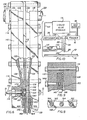
- Fig. 1 the extruder 22 is shown to include three elongated flat blocks; namely, infeed block 42, bypass block 44 and central coupling block 46. These blocks are secured together detachably in face-abutting relationship by means of bolts 48.
- infeed block 42 The inner surface of infeed block 42 is recessed to form an infeed passageway assembly 24 of a plurality of passageways.
- all of these passageways extend substantially equal distances from the connection of the foam inlet conduit 20 to the coupling port 26 in the center block 46.
- the inlet conduit is coupled to an infeed port 50 which communicates with the central point of an elongated main passageway 52.
- Each of the opposite outer ends of this main passageway communicates with the central point of a secondary passageway 54.
- Each of the opposite outer ends of each secondary passageway communicates with the inner end of a tertiary passageway 56.
- each of the opposite outer ends of each tertiary passageway communicates with the inner of a distribution passageway 58.
- Each distribution passageway 58 is triangular in plan view (Fig. 3). Although each passageway 58 may be of uniform dimension in transverse section, it preferably is triangular, as shown in Fig. 1. In this form it is also of maximum width, in transverse section, at its inner end, tapering to narrower width in transverse section at its outer end where it communicates with a plurality of the coupling ports 26 in the center block 46. For this purpose the distribution passageway is of maximum width in plan at its outer end, tapering to narrower width at its inner end. These dimensions preferably are chosen so that the longitudinal cross-sectional area of the distribution passageway remains substantially constant from the outer end to the inner end. It is by this means that there is achieved substantially uniform delivery of foamed glue through all of the coupling ports 26.
- the ends of the coupling ports 26 opposite the distribution passageway 58 communicate with longitudinally elongated valve chamber 60.
- This chamber is formed as a recess in the surface of bypass block 44 facing the central block 46.
- the upper end of the valve chamber communicates with the wide inner ends of collector passageways 62.
- These collector passageways are constructed in the manner of the distribution passageway 58, but function to receive bypassed foamed glue for return to the reservoir 14, preferably through defoamer 38.
- the inner ends of adjacent pairs of collector passageways 62 are connected to the opposite ends of tertiary bypass passageways 64.
- Communicating with the central point of adjacent pairs of tertiary bypass passageways 64 are the opposite ends of secondary bypass passageways 66.
- Communicating with the central point of adjacent pairs of secondary bypass passageways are the opposite ends of a main bypass passageway 68.
- the central point of the main bypass passageway communicates with bypass port 70 which connects with bypass conduit 36.
- Valve chamber 60 contains elongated, C-shaped valve body 72 which is secured removably therein by means of bolts (not shown) extended through openings in the bypass block 44.
- bolts not shown
- Within the cavity of the valve body are three elongated, parallel clamp bars 74, 76 and 78. These clamp bars are of trapezoidal shape in cross section, the central bar 78 having its shorter side facing away from the center block 46 and the outer bars 74 and 76 having their shorter sides facing the center block.
- the outer bars 74 and 76 mount elongated, C-shaped valve members 80 and 82, respectively, These valve members are made of rubber or other suitably elastic material. Each has inwardly angles, longitudinally elongated lugs 84 on their terminal edges arranged to engage elongated notches 86 on the outward edges of the clamp bars.
- the outer clamp bars are secured to the valve body 72 by means of bolts 88, and the central bar 78 is secured between the outer bars by bolts 90.
- the central bar thus wedges between the outer bars and clamps the inner sides of the valve members 80 and 82 between them.
- the outer sides of the valve members are clamped between the bars and the confronting inner sides of the legs of the C-shaped body 72.
- closure bars 92 are interposed between the valve members and the central block 46. They are provided with smoothly contoured inner ends 92' which allow flexing of the elastic valve members with minimum fatigue. The valve members thus are afforded a long operating life.
- each valve member 80 and 82 is interposed between the inwardly facing side of the associated clamp bars 74 and 76, respectively, and the inner portion of the valve chamber 60 defined by the confronting surface of the central block 46.
- Each of the bars is provided with a transverse port 94 which is connected to a conduit 96 extending outwardly through the bypass block 44 for connection to the controller 34 (Fig. 5).
- the controller includes a source of fluid under pressure, preferably air pressure, and a selector valve by which air pressure is delivered selectively to the valve members 80 and 82.
- Fig. 1 illustrates the condition in which air under pressure is delivered to valve member 80 to extend its central portion into sealing contact with the confronting surface of central block 46. Coupling ports 26 thus are communicated through valve chamber 60 and past retracted valve member 82 to the collector passageways 62.
- valve chamber 60 on the side of valve member 80 opposite the coupling port 26 communicates with outlet orifice assembly 28 through outfeed passageway 98.
- this assembly includes an elongated orifice block 100 provided with a multiplicity of longitudinally spaced apart orifices 102. As illustrated, these orifices are fitted with tubular orifice inserts 104 which project outwardly beyond the outer side of the block 100 to produce discrete extrusions of foamed glue. Without these inserts, or other means providing separated nozzles, foamed glue extruded through the orifices 102 tends to creep along the outer side of the block-100 and join together, forming irregularly spaced and sized clusters of foamed glue extrusions.
- Liquid glue in storage reservoir 14 is delivered to the foamer 16, and the foamed glue outfeed is delivered through conduit 20 to the infeed port 50 and thence to the main infeed passageway 52.
- the foamed glue passes along the infeed passageway 52 in both directions from the port 50, and thence into the secondary passageways 54. These passageways are about one-half the cross sectional area of the main infeed passageway 52, and therefore they accept the glue with no substantial increase or decrease in pressure or volume flow.
- the glue enters the tertiary infeed passageways 56. These also are about one-half the cross sectional area of the secondary infeed passageway 54, and therefore the glue progresses through them with no substantial decrease or increase in pressure or volume flow.
- the controller 34 operates to retract the valve member 80 and to extend the valve member 82 into sealing contact with the confronting surface of the coupling block 46.
- the chamber 60 thus is closed against the flow of foamed glue toward the bypass collector passageways 62.
- valve member 80 With valve member 80 retracted, foamed glue flows past it in chamber 60 and into the outlet orifice inserts 104, exiting the outer ends thereof in discreet, spaced apart strings of foamed glue. These strings of foamed glue gravitate downward onto the veneer 10 passing underneath.
- controller 34 is operated to retract the valve member 82 and to extend valve member 80 into sealing contact with the coupling block 46. Foamed glue thus is prevented from continuing to flow into the outlet orifice assembly.
- the outlet orifice assembly may be removed from its mounting between the bypass block 44 and coupling block 46 by unloosening the bolts 48 and spreading the blocks 44 and 46 apart sufficiently to effect disengagement of the outlet orifice block 100.
- the controller 34 having extended the valve member 80 and retracted the valve member 82, foamed glue passing through the coupling ports 26 now is diverted through the passageway 60 past the retracted valve member 82 and into the adjacent wide ends of the bypass collector passageways 62.
- the foamed glue progresses upward through these passageways, with substantially no change in pressure or volume flow, thence into the tertiary bypass passageways 64 and into the secondary bypass passageways 66 to the main bypass passageway 68.
- the cross sectional areas of these various bypass passageways are such as to afford passage of the foamed glue therethrough with substantially no increase or decrease in pressure or volume flow. Accordingly, upon switching of the valve members to resume outward feeding of foamed glue through the outlet orifice assembly, the physical character and volume flow of foamed glue from the outlet remains substantially unchanged.
- bypassed foamed glue passes from the main bypass passageway 68 through the bypass port 70 and into bypass conduit 36 from whence it is returned to the storage reservoir 14, preferably through the defoamer 38.
- the extruder 106 is shown to include three elongated flat blocks; namely, infeed block 108, bypass block 110 and central coupling block 112. These blocks are secured together detachably in face-abutting relationship by means of bolts 114.
- infeed block 108 The inner surface of infeed block 108 is recessed to form an infeed passageway assembly 24 of a plurality of passageways. As in the first embodiment described, all of these passageways extend substantially equal distances from the connection of the foam inlet conduit 20 to the outlet orifice assembly 28.
- the inlet conduit is coupled to an infeed port 118 which communicates with an elongated main passageway 120.
- the opposite outer end of this main passageway communicates with the central point of a secondary passageway 122.
- Each of the opposite outer ends of the secondary passageway communicates with the inner end of a distribution passageway 124.
- each distribution passageway 124 is triangular in plan view as well as in transverse section. It is also of maximum width, in transverse section, at its inner end, tapering to narrower width in transverse section at its outer end where it is of maximum width in plan.
- the outer ends of the distribution passageways 124 communicate with longitudinally and laterally elongated slot 126.
- This slot is formed as a recess in the surface of infeed block 108. Its upper portion faces the lower portion of central block 112 and its lower portion faces the confronting surface of bypass block 110.
- the upper portion of slot 126 communicates with a transverse slot 128 which is formed between the bottom end of central block 112 and the upper end of an inner extension of the bypass block 110.
- the slot communicates with the wide inner ends of collector passageways 130.
- These collector passageways are constructed in the manner of the distribution passageways 124, but function to receive bypassed foamed glue for return to the reservoir 14, preferably through defoamer 38.
- the inner ends of the pair of collector passageways 130 are connected to the opposite ends of secondary bypass passageway 132 the central point of which communicates with the inner end of main bypass passageway 134.
- the outer end of this passageway communicates with bypass port 136 which connects with bypass conduit 36 through control valve 138.
- an elongated clamp bar 142 Within an elongated valve chamber 140 in the inner side of bypass block 110 is an elongated clamp bar 142. It is of trapezoidal shape in cross section, having its shorter side facing away from the slot 126. It is secured removably in the valve chamber by bolts 144.
- the clamp bar 142 mounts an elongated, C-shaped valve member 146. It is made of rubber or other suitably elastic material and has inwardly angled, longitudinally elongated lugs 148 on its terminal edges arranged to engage elongated notches 150 on the outward edges of the clamp bar 142.
- valve member 146 The opposite ends of the valve member 146 are sealed against the escape of foamed glue by sealing engagement with the confronting surfaces of the opposite end portions of the infeed block 108 (Fig. 9). Tapered grooves 152 in the infeed block inwardly of the said end portions communicate with the slot 126 to allow flexing of the elastic valve member with minimum fatigue. The valve member thus is afforded a long operating life.
- the central portion of the valve member 146 confronts the slot 126.
- the supporting clamp bar 142 is provided with a transverse port 154 which is connected to a conduit 156 extending outwardly through the bypass block 110 for connection to the controller 34 (Fig. 10).
- the controller includes a source of fluid under pressure, preferably air pressure, and a control valve by which air pressure is delivered selectively to the valve member 146.
- Fig. 6 illustrates the condition in which air pressure has been relieved from the valve member to retract its central portion from the slot 126.
- this outlet orifice assembly includes an elongated orifice block 158 provided with a multiplicity of longitudinally spaced apart orifices 160. As illustrated, the outer portion 160' of each of these orifices is flared outwardly to larger diameter. The degree of flare may be varied to achieve the desired velocity and diameter of foamed extrusion.
- Each orifice terminates in an isolated edge 162 defined by a counterbore 164 recessed into the block surrounding said edge. These spaced edges 162 produce discrete extrusions of foamed glue, in the manner of the inserts 104 previously described.
- Tapered grooves 166 in the confronting sides of the infeed block 108 and bypass block 110 form a channel for the removable reception of the orifice block 158.
- the latter is provided with correspondingly sloped shoulders, whereby the block is wedged into sealing position but may be removed by slipping it laterally outward from the larger end of the groove.
- the present invention provides a foamed liquid extruder which is of simplified construction, affording economical manufacture, maintenance and repair and which assures that the extrusion of foamed liquid is of uniform character and volume flow throughout the entire length of the outlet orifice assembly.
- the outfeed passageway 98 in Fig. 1 may be formed in infeed block 42, as in Fig. 6, and the feed control valve 80 mounted in the infeed block for association therewith, with bypass control valve 82 retained in the position shown, for association with bypass passageways 62.
- each valve preferably is constructed in the manner of valve 146 (Fig. 6).
- a similar arrangement may be used in the embodiment of Fig. 6, i.e. valve 146 mounted in infeed block 108 and a similar valve mounted in bypass block 110 for association with the vertical section of slot 128.
- Such an arrangement eliminates the control valve 138 and controls the foam bypass closer to the feed slot 126.
Landscapes
- Engineering & Computer Science (AREA)
- Mechanical Engineering (AREA)
- Manufacturing & Machinery (AREA)
- Coating Apparatus (AREA)
- Extrusion Moulding Of Plastics Or The Like (AREA)
- Molding Of Porous Articles (AREA)
Claims (4)
Priority Applications (3)
| Application Number | Priority Date | Filing Date | Title |
|---|---|---|---|
| US06/419,221 US4470789A (en) | 1982-09-17 | 1982-09-17 | Extruder for foamed liquids |
| DE8484201289T DE3478667D1 (en) | 1984-09-07 | 1984-09-07 | Extruder for foamed liquids |
| EP84201289A EP0173772B1 (de) | 1982-09-17 | 1984-09-07 | Extruder für Schaumflüssgkeiten |
Applications Claiming Priority (2)
| Application Number | Priority Date | Filing Date | Title |
|---|---|---|---|
| US06/419,221 US4470789A (en) | 1982-09-17 | 1982-09-17 | Extruder for foamed liquids |
| EP84201289A EP0173772B1 (de) | 1982-09-17 | 1984-09-07 | Extruder für Schaumflüssgkeiten |
Publications (3)
| Publication Number | Publication Date |
|---|---|
| EP0173772A2 EP0173772A2 (de) | 1986-03-12 |
| EP0173772A3 EP0173772A3 (en) | 1987-04-15 |
| EP0173772B1 true EP0173772B1 (de) | 1989-06-14 |
Family
ID=26092881
Family Applications (1)
| Application Number | Title | Priority Date | Filing Date |
|---|---|---|---|
| EP84201289A Expired EP0173772B1 (de) | 1982-09-17 | 1984-09-07 | Extruder für Schaumflüssgkeiten |
Country Status (2)
| Country | Link |
|---|---|
| US (1) | US4470789A (de) |
| EP (1) | EP0173772B1 (de) |
Families Citing this family (14)
| Publication number | Priority date | Publication date | Assignee | Title |
|---|---|---|---|---|
| US4624213A (en) * | 1985-08-27 | 1986-11-25 | Armstrong World Industries, Inc. | Curtain coating apparatus and method of use |
| US4990293A (en) * | 1987-11-09 | 1991-02-05 | Regents Of The University Of Minnesota | Process of and apparatus for extruding a reactive polymer mixture |
| AU625574B2 (en) * | 1987-11-09 | 1992-07-16 | Regents Of The University Of Minnesota | A continuous extrusion die for extruding a reactive polymer mixture |
| US4983109A (en) * | 1988-01-14 | 1991-01-08 | Nordson Corporation | Spray head attachment for metering gear head |
| FR2633409A1 (fr) * | 1988-06-24 | 1989-12-29 | Secmer Entreprise Sarl | Appareil pour la coulee calibree d'un liquide a doser |
| DE4243277C2 (de) * | 1992-12-21 | 1997-05-07 | Bayer Ag | Vorrichtung zum kontinuierlichen Herstellen von Schaumstoffbahnen, insbesondere Hartschaumstoffplatten |
| US5556471A (en) * | 1994-05-17 | 1996-09-17 | Nordson Corporation | Method and apparatus for dispensing foam materials |
| FI106470B (fi) | 1998-03-09 | 2001-02-15 | Neste Chemicals Oy | Vaahdotettu hartsiliima ja sen käyttö puupohjaisten levyjen liimaamiseen |
| WO2002076705A1 (en) * | 2001-03-23 | 2002-10-03 | Rpc Cobelplast Montonate S.R.L. | Extrusion head with adjustable width, for the extrusion of fast thermodegradable polymers, and extrusion process making use thereof |
| FI113527B (fi) * | 2002-12-31 | 2004-05-14 | Raute Oyj | Suutinyksikkö |
| EP1767332A4 (de) * | 2004-05-26 | 2008-10-15 | Sekisui Chemical Co Ltd | Formwerkzeug zum extrudieren, extrusionsformvorrichtung, verfahren zur herstellung eines flächengebildes aus thermoplastischem harz und verfahren zur herstellung von thermoplastischem harzschaum |
| US20060088401A1 (en) * | 2004-10-26 | 2006-04-27 | Mahindra & Mahindra Ltd | Tamper-proof sealing mechanism for various adjustment means |
| EP2352630A1 (de) * | 2008-12-01 | 2011-08-10 | DSM IP Assets B.V. | Verfahren zur herstellung eines uhmwpe-bands, breitschlitzextrusionsdüse und hergestelltes uhmwpe-band davon |
| DE102009048820A1 (de) * | 2009-10-09 | 2011-04-14 | Andritz Küsters Gmbh | Vorhang-Auftragswerk |
Family Cites Families (20)
| Publication number | Priority date | Publication date | Assignee | Title |
|---|---|---|---|---|
| US3155540A (en) * | 1959-06-15 | 1964-11-03 | Landers Corp | Apparatus for the extrusion coating of fabric or like materials |
| US3227136A (en) * | 1961-10-26 | 1966-01-04 | Eastman Kodak Co | Extrusion coating apparatus |
| US3190259A (en) * | 1962-12-21 | 1965-06-22 | Textile Machine Works | Adhesive applicator for carton sealing machines |
| US3277868A (en) * | 1963-02-18 | 1966-10-11 | Lockwood Tech | Adhesive applicator including adhesiverecirculation means |
| US3286689A (en) * | 1963-10-14 | 1966-11-22 | Textile Machine Works | Adhesive applicator |
| US3479989A (en) * | 1967-11-28 | 1969-11-25 | Eastman Kodak Co | Extrusion coating apparatus |
| US3832427A (en) * | 1968-10-14 | 1974-08-27 | Guthrie Ind Ltd | Process for continuously forming a polymeric resinous layer from a multicomponent liquid reactive mixture |
| CH497262A (de) * | 1969-03-06 | 1970-10-15 | Semperit Ag | Spritzgiessform mit einem Absperrorgan im Einspritzkanal, insbesondere für die Herstellung von Formkörpern aus schaumfähigem Polyurethan |
| US3602193A (en) * | 1969-04-10 | 1971-08-31 | John R Adams | Apparatus for preparing coatings with extrusions |
| US3965860A (en) * | 1970-10-15 | 1976-06-29 | Pacific Adhesives, Inc. | Plywood manufacture using foamed glues |
| US3814628A (en) * | 1972-04-17 | 1974-06-04 | Gates Rubber Co | Battery paste pumping and metering system |
| US3865078A (en) * | 1972-06-05 | 1975-02-11 | Du Pont | Foam finish applicator |
| US3905329A (en) * | 1973-03-30 | 1975-09-16 | Pacific Adhesives Company Inc | Apparatus for the uniform application of foamed liquid mixtures to substrates |
| US3865535A (en) * | 1973-06-04 | 1975-02-11 | Beloit Corp | Two piece die assembly for extruding micro-filaments |
| FR2257192A5 (en) * | 1973-12-14 | 1975-08-01 | Kodak Pathe | Appts for depositing magnetic layer on moving strip - pumps slurry through porous plug to evenly separate particles |
| GB1512061A (en) * | 1974-05-14 | 1978-05-24 | Reinz Dichtungs Gmbh | Application of coatings |
| US4017240A (en) * | 1975-11-19 | 1977-04-12 | Rubbermaid Incorporated | Die for extruding sheet material |
| US4113152A (en) * | 1977-03-14 | 1978-09-12 | Schmidt Robert W | Adhesive dispensing device |
| US4159355A (en) * | 1977-11-14 | 1979-06-26 | Scott Paper Company | Foam bonding |
| DE3016445A1 (de) * | 1980-04-29 | 1981-11-05 | Bayer Ag, 5090 Leverkusen | Vorrichtung zum auftragen eines insbesondere schaumstoff bildenden reaktionsgemisches aus mindestends zwei fliessfaehigen komponenten auf eine wandernde unterlage |
-
1982
- 1982-09-17 US US06/419,221 patent/US4470789A/en not_active Expired - Lifetime
-
1984
- 1984-09-07 EP EP84201289A patent/EP0173772B1/de not_active Expired
Also Published As
| Publication number | Publication date |
|---|---|
| US4470789A (en) | 1984-09-11 |
| EP0173772A2 (de) | 1986-03-12 |
| EP0173772A3 (en) | 1987-04-15 |
Similar Documents
| Publication | Publication Date | Title |
|---|---|---|
| US4470789A (en) | Extruder for foamed liquids | |
| CA1291679C (en) | Method and apparatus for applying narrow, closely spaced beads of viscous liquid to a substrate | |
| EP0936000B1 (de) | Modulare Auftragseinheit mit schnell auswechselbarem Mundstück oder Düse | |
| US5992453A (en) | Flow-dividing arrangement | |
| USRE39399E1 (en) | Segmented die for applying hot melt adhesives or other polymer melts | |
| EP0651677B1 (de) | Vorrichtung und verfahren zum aufbringen von schaumbeschichtungen | |
| EP0672462B1 (de) | Flüssigkeitsapplikator | |
| US5445509A (en) | Meltblowing die | |
| US5683036A (en) | Apparatus for applying discrete coatings | |
| CA2352355A1 (en) | Droplet deposition apparatus | |
| US6375099B1 (en) | Split output adhesive nozzle assembly | |
| CA2210387A1 (en) | Liquid discharge head, recovery method and manufacturing method for liquid discharge head, and liquid discharge apparatus using liquid discharge head | |
| CA2260075A1 (en) | Method and apparatus for applying a material to a web | |
| SE446827B (sv) | Anordning for alstrande av ett smeltskumlim | |
| CN101396685A (zh) | 缝式喷嘴组件、喷枪、垫板及挤压可发泡熔融材料的方法 | |
| WO1996034132A1 (en) | Modular meltblowing die | |
| ATE269169T1 (de) | Flüssigkeitsabgabevorrichtung und -verfahren | |
| US20050015050A1 (en) | Apparatus for depositing fluid material onto a substrate | |
| EP0888194B1 (de) | Vorrichtung und verfahren zum auftragen eines mediums auf ein bewegliches, bahnförmiges material | |
| US5094399A (en) | Application of thermal-cure materials | |
| CA1221826A (en) | Extruder for foamed liquids | |
| EP0866152B1 (de) | Vorrichtung und Verfahnren zum Schmelzblasen | |
| JPH02169065A (ja) | スリットノズル | |
| EP1101537B1 (de) | Beschichtungsvorrichtung, insbesondere für thermoplastisches Material | |
| FI79801C (fi) | Extruder foer skummade vaetskor. |
Legal Events
| Date | Code | Title | Description |
|---|---|---|---|
| PUAI | Public reference made under article 153(3) epc to a published international application that has entered the european phase |
Free format text: ORIGINAL CODE: 0009012 |
|
| AK | Designated contracting states |
Kind code of ref document: A2 Designated state(s): DE FR GB IT SE |
|
| PUAL | Search report despatched |
Free format text: ORIGINAL CODE: 0009013 |
|
| AK | Designated contracting states |
Kind code of ref document: A3 Designated state(s): DE FR GB IT SE |
|
| 17P | Request for examination filed |
Effective date: 19871002 |
|
| 17Q | First examination report despatched |
Effective date: 19880422 |
|
| GRAA | (expected) grant |
Free format text: ORIGINAL CODE: 0009210 |
|
| AK | Designated contracting states |
Kind code of ref document: B1 Designated state(s): DE FR GB IT SE |
|
| REF | Corresponds to: |
Ref document number: 3478667 Country of ref document: DE Date of ref document: 19890720 |
|
| ITF | It: translation for a ep patent filed | ||
| ET | Fr: translation filed | ||
| PLBE | No opposition filed within time limit |
Free format text: ORIGINAL CODE: 0009261 |
|
| STAA | Information on the status of an ep patent application or granted ep patent |
Free format text: STATUS: NO OPPOSITION FILED WITHIN TIME LIMIT |
|
| 26N | No opposition filed | ||
| ITTA | It: last paid annual fee | ||
| PGFP | Annual fee paid to national office [announced via postgrant information from national office to epo] |
Ref country code: GB Payment date: 19930901 Year of fee payment: 10 |
|
| PGFP | Annual fee paid to national office [announced via postgrant information from national office to epo] |
Ref country code: SE Payment date: 19930917 Year of fee payment: 10 |
|
| PG25 | Lapsed in a contracting state [announced via postgrant information from national office to epo] |
Ref country code: GB Effective date: 19940907 |
|
| PG25 | Lapsed in a contracting state [announced via postgrant information from national office to epo] |
Ref country code: SE Effective date: 19940908 |
|
| PGFP | Annual fee paid to national office [announced via postgrant information from national office to epo] |
Ref country code: DE Payment date: 19940921 Year of fee payment: 11 |
|
| PGFP | Annual fee paid to national office [announced via postgrant information from national office to epo] |
Ref country code: FR Payment date: 19940926 Year of fee payment: 11 |
|
| EAL | Se: european patent in force in sweden |
Ref document number: 84201289.0 |
|
| GBPC | Gb: european patent ceased through non-payment of renewal fee |
Effective date: 19940907 |
|
| EUG | Se: european patent has lapsed |
Ref document number: 84201289.0 |
|
| PG25 | Lapsed in a contracting state [announced via postgrant information from national office to epo] |
Ref country code: FR Effective date: 19960531 |
|
| PG25 | Lapsed in a contracting state [announced via postgrant information from national office to epo] |
Ref country code: DE Effective date: 19960601 |
|
| REG | Reference to a national code |
Ref country code: FR Ref legal event code: ST |