EP0172796B1 - Electrically activated lock - Google Patents
Electrically activated lock Download PDFInfo
- Publication number
- EP0172796B1 EP0172796B1 EP85850242A EP85850242A EP0172796B1 EP 0172796 B1 EP0172796 B1 EP 0172796B1 EP 85850242 A EP85850242 A EP 85850242A EP 85850242 A EP85850242 A EP 85850242A EP 0172796 B1 EP0172796 B1 EP 0172796B1
- Authority
- EP
- European Patent Office
- Prior art keywords
- lock
- hook
- knob
- shaft
- motor
- Prior art date
- Legal status (The legal status is an assumption and is not a legal conclusion. Google has not performed a legal analysis and makes no representation as to the accuracy of the status listed.)
- Expired
Links
Images

Classifications
-
- E—FIXED CONSTRUCTIONS
- E05—LOCKS; KEYS; WINDOW OR DOOR FITTINGS; SAFES
- E05B—LOCKS; ACCESSORIES THEREFOR; HANDCUFFS
- E05B47/00—Operating or controlling locks or other fastening devices by electric or magnetic means
- E05B47/06—Controlling mechanically-operated bolts by electro-magnetically-operated detents
- E05B47/0676—Controlling mechanically-operated bolts by electro-magnetically-operated detents by disconnecting the handle
- E05B47/068—Controlling mechanically-operated bolts by electro-magnetically-operated detents by disconnecting the handle axially, i.e. with an axially disengaging coupling element
-
- E—FIXED CONSTRUCTIONS
- E05—LOCKS; KEYS; WINDOW OR DOOR FITTINGS; SAFES
- E05B—LOCKS; ACCESSORIES THEREFOR; HANDCUFFS
- E05B47/00—Operating or controlling locks or other fastening devices by electric or magnetic means
- E05B47/0001—Operating or controlling locks or other fastening devices by electric or magnetic means with electric actuators; Constructional features thereof
- E05B2047/0014—Constructional features of actuators or power transmissions therefor
- E05B2047/0018—Details of actuator transmissions
- E05B2047/0026—Clutches, couplings or braking arrangements
- E05B2047/0031—Clutches, couplings or braking arrangements of the elastic type
-
- Y—GENERAL TAGGING OF NEW TECHNOLOGICAL DEVELOPMENTS; GENERAL TAGGING OF CROSS-SECTIONAL TECHNOLOGIES SPANNING OVER SEVERAL SECTIONS OF THE IPC; TECHNICAL SUBJECTS COVERED BY FORMER USPC CROSS-REFERENCE ART COLLECTIONS [XRACs] AND DIGESTS
- Y10—TECHNICAL SUBJECTS COVERED BY FORMER USPC
- Y10S—TECHNICAL SUBJECTS COVERED BY FORMER USPC CROSS-REFERENCE ART COLLECTIONS [XRACs] AND DIGESTS
- Y10S292/00—Closure fasteners
- Y10S292/27—Disconnectable handle
-
- Y—GENERAL TAGGING OF NEW TECHNOLOGICAL DEVELOPMENTS; GENERAL TAGGING OF CROSS-SECTIONAL TECHNOLOGIES SPANNING OVER SEVERAL SECTIONS OF THE IPC; TECHNICAL SUBJECTS COVERED BY FORMER USPC CROSS-REFERENCE ART COLLECTIONS [XRACs] AND DIGESTS
- Y10—TECHNICAL SUBJECTS COVERED BY FORMER USPC
- Y10S—TECHNICAL SUBJECTS COVERED BY FORMER USPC CROSS-REFERENCE ART COLLECTIONS [XRACs] AND DIGESTS
- Y10S292/00—Closure fasteners
- Y10S292/52—Rollbacks
-
- Y—GENERAL TAGGING OF NEW TECHNOLOGICAL DEVELOPMENTS; GENERAL TAGGING OF CROSS-SECTIONAL TECHNOLOGIES SPANNING OVER SEVERAL SECTIONS OF THE IPC; TECHNICAL SUBJECTS COVERED BY FORMER USPC CROSS-REFERENCE ART COLLECTIONS [XRACs] AND DIGESTS
- Y10—TECHNICAL SUBJECTS COVERED BY FORMER USPC
- Y10T—TECHNICAL SUBJECTS COVERED BY FORMER US CLASSIFICATION
- Y10T292/00—Closure fasteners
- Y10T292/57—Operators with knobs or handles
-
- Y—GENERAL TAGGING OF NEW TECHNOLOGICAL DEVELOPMENTS; GENERAL TAGGING OF CROSS-SECTIONAL TECHNOLOGIES SPANNING OVER SEVERAL SECTIONS OF THE IPC; TECHNICAL SUBJECTS COVERED BY FORMER USPC CROSS-REFERENCE ART COLLECTIONS [XRACs] AND DIGESTS
- Y10—TECHNICAL SUBJECTS COVERED BY FORMER USPC
- Y10T—TECHNICAL SUBJECTS COVERED BY FORMER US CLASSIFICATION
- Y10T292/00—Closure fasteners
- Y10T292/59—Rollback and spindle connection
-
- Y—GENERAL TAGGING OF NEW TECHNOLOGICAL DEVELOPMENTS; GENERAL TAGGING OF CROSS-SECTIONAL TECHNOLOGIES SPANNING OVER SEVERAL SECTIONS OF THE IPC; TECHNICAL SUBJECTS COVERED BY FORMER USPC CROSS-REFERENCE ART COLLECTIONS [XRACs] AND DIGESTS
- Y10—TECHNICAL SUBJECTS COVERED BY FORMER USPC
- Y10T—TECHNICAL SUBJECTS COVERED BY FORMER US CLASSIFICATION
- Y10T70/00—Locks
- Y10T70/50—Special application
- Y10T70/5093—For closures
- Y10T70/5155—Door
- Y10T70/5199—Swinging door
- Y10T70/5372—Locking latch bolts, biased
- Y10T70/5385—Spring projected
- Y10T70/5389—Manually operable
- Y10T70/5394—Directly acting dog for exterior, manual, bolt manipulator
- Y10T70/5416—Exterior manipulator declutched from bolt when dogged
-
- Y—GENERAL TAGGING OF NEW TECHNOLOGICAL DEVELOPMENTS; GENERAL TAGGING OF CROSS-SECTIONAL TECHNOLOGIES SPANNING OVER SEVERAL SECTIONS OF THE IPC; TECHNICAL SUBJECTS COVERED BY FORMER USPC CROSS-REFERENCE ART COLLECTIONS [XRACs] AND DIGESTS
- Y10—TECHNICAL SUBJECTS COVERED BY FORMER USPC
- Y10T—TECHNICAL SUBJECTS COVERED BY FORMER US CLASSIFICATION
- Y10T70/00—Locks
- Y10T70/50—Special application
- Y10T70/5611—For control and machine elements
- Y10T70/5757—Handle, handwheel or knob
- Y10T70/5765—Rotary or swinging
- Y10T70/5805—Freely movable when locked
-
- Y—GENERAL TAGGING OF NEW TECHNOLOGICAL DEVELOPMENTS; GENERAL TAGGING OF CROSS-SECTIONAL TECHNOLOGIES SPANNING OVER SEVERAL SECTIONS OF THE IPC; TECHNICAL SUBJECTS COVERED BY FORMER USPC CROSS-REFERENCE ART COLLECTIONS [XRACs] AND DIGESTS
- Y10—TECHNICAL SUBJECTS COVERED BY FORMER USPC
- Y10T—TECHNICAL SUBJECTS COVERED BY FORMER US CLASSIFICATION
- Y10T70/00—Locks
- Y10T70/70—Operating mechanism
- Y10T70/7051—Using a powered device [e.g., motor]
- Y10T70/7062—Electrical type [e.g., solenoid]
- Y10T70/713—Dogging manual operator
Definitions
- the present invention relates to an electrically activated lock as defined in the preamble of claim 1.
- the lock should be so designed as to enable it to be released from its locking mode from one side of the lock, i.e. from one side of the door, without requiring an electric signal to be produced, i.e. solely by turning the knob or like device. It should also be difficult, of course, to force the lock, and the lock should be constructed so that there is little risk of the lock being damaged if an attempt is made to force the lock from the outside.
- the drawings illustrate part of a lock according to the invention which is intended to be fitted to the outside of a door for example, in which there is mounted a conventional lock case incorporating at least one lock bolt.
- the illustrated lock part relevant to the concept of the invention comprises a housing 1 which is intended to be mounted on the outside of the door 2, shown only schematically in the drawings, centrally of the lock case (not shown in detail) fitted in the door and incorporating at least one lock bolt for locking said door.
- the upper part 1a of the housing 1 is adapted to enable it to receive a magnetic card 3, and incorporates the requisite electrical components and circuits for reading information registered on the card and for generating an electric lock- release signal upon receiving a magnetic card 3 intended therefor.
- the arrangement for generating this electrical lock-release signal may have any suitable form, and may comprise the arrangement described and illustrated in European Patent Application No. 84850102-9, for example. Other arrangements may be used for this purpose, however, for example a button array or the like with which a lockrelease code number can be inserted, to give rise to the aforesaid lock-release signal.
- a knob 4 or like device Rotatably mounted in the forward wall lb of the housing 1 is a knob 4 or like device.
- a shaft 5 associated with the lock case (not shown in detail) is rotatably journalled in the rear wall 1c of the housing 1 facing the door 2, such that the axis of rotation of the shaft is coaxial with the axis of rotation of the knob 4.
- the shaft 5 associated with the lock case is arranged to retract the lock bolt to its door-release position upon rotation of the shaft 5 in a conventional manner.
- a sleeve 6 is suitably journalled for rotation in the wall Ic and extended through the rearwati 1c of the housing, this sleeve being provided with, for example, a square hole into which the shaft 5 associated with the lock case projects, said shaft being similarly of square cross-section.
- an electrically actuable coupling arrangement Arranged between the knob 4 and the sleeve 6 is an electrically actuable coupling arrangement which normally takes a disengaged mode, such that no connection exists between the knob 4 and the sleeve 6, therewith rendering it impossible to retract the lock bolt with the aid of the knob 4, but which can be actuated by means of an electric lock-release signal in a manner to connect the knob 4 with the sleeve 6, therewith enabling the sleeve 6, and also the shaft 5, to be rotated by means of the knob 4, to release the lock.
- the electrically actuable coupling arrangement includes a first coupling element in the form of a plate 7 which is non-rotatably mounted on the inner end of the knob 4 and which is provided around its periphery with at least one tooth or shoulder 7a, and a second coupling element in the form of a bracket or holder 8 which is arranged on the inner end of the sleeve 6 and in which a hook 9 is pivotably mounted.
- the plate 7 is biased by a spring 10, which normally holds the plate 7 and therewith the knob 4 inthe position shown in full lines in Figure 3.
- Rotation of the plate 7 and the knob 4 in a clockwise direction, as seen in Figure 3, is limited by a stationary abutment peg 11, against which an abutment surface 12 on the plate 7 engages.
- the pivotable hook 9 on the bracket 8 is spring-biased in a counter clockwise direction, as illustrated in Figure 1, and is normally held in the outwardly swung position illustrated in full lines in Figures 1 and 2. In this outwardly swung position, the hook 9 lies outside the path moved by the tooth or shoulder 7a on the plate 7 when the knob 4, is pressed down or turned, and hence the rotational movement of the knob 4 cannot be transmitted to the sleeve 6 and therewith the shaft 5 of the lock case.
- this electric lock-release signal starts an electric motor 14 which drives, over gear drive 15, a shaft 16 on which an eccentric 17 and a cam plate 18 are mounted.
- the cam plate 18 acts upon a microswitch 22 in a manner such that when the motor 14 is started from the position illustrated in Figure 1, through the agency of an electric lock- release signal, the shaft 16 together with the eccentric 17 and the cam plate 18 are rotated through one half revolution, whereupon the rotary movement is stopped by action of the microswitch 22.
- the motor 14 is re-started and rotates the shaft 16, the eccentric 17 and the cam plate 18 through a further half revolution, to the position illustrated in full lines in Figure 1, in which position the motor is again stopped by action of the microswitch 22.
- the pivotable hook 9 is connected to the eccentric 17 on the shaft 16 by means of a link mechanism incorporating two link arms 19 and 20.
- the other link arm 20, which in the illustrated embodiment comprises a slightly springy metal wire, has the shape of a hairpin and is pivotally mounted on a stationary peg 21, in a manner such that the two legs of the hairpin- shaped link arm 20 lie against respective opposite sides of the eccentric 17.
- the pivotal connecting point between the two link arms 19 and 20 is located approximately on the common rotational axis of the knob 4 and the sleeve 6.
- the connecting joint has the form of a circular annular eye 20a on the link arm 20 and an eye 19a on the link arm 19, the eye 19a being freely movable around the circular eye 20a on the link arm 20.
- the annular eye 20a on the link arm 20 is located substantially concentrically in relation to the common axis of rotation of the knob 4 and the sleeve 6.
- the electric motor 14 is able to continue to rotate through one half revolution when manipulating the lock between a locking and releasing position in the aforedescribed manner, even though, for some reason or other, mechanical locking should occur between the hook 9 and the plate 7 in a manner to prevent the hook 9 from being swung in the manner intended. Due to the fact that the motor 14 will rotate in such cases through one half revolution and be automatically stopped by the microswitch 22, overloading of and damage to the motor is avoided.
- the lock illustrated in full lines in the drawing is constructed and mounted for a righthand door.
- the knob 4 can be mounted in the manner shown in chain lines in Figure 3, while at the same time reversing the plate 7 and mounting it on the knob in the position shown in chain lines in Figure 3.
- the spring 10 is also reversed, so that it strives to rotate the plate 7, and therewith the knob 4, in a counter clock-wise direction in Figure 3.
- the plate 7 is also able to co-act with the hook 9 on the bracket 8 in this new position, in the same manner-as that aforedescribed.
- a lock according to the invention can be constructed in various ways over and above that described by way of example in the aforegoing.
- the electrically actuable coupling arrangement between the knob or like device and the lock-case shaft determining the position of the lock bolt can have,various mutually different forms.
- the electrical operating means need not necessa ⁇ y comprise an electric rotatable motor, but may have the form of solenoid or some other electrical operating means.
- a rotatable motor has the advantage that it takes current only while it is rotating, and hence the total current consumption of the lock is very small.
Landscapes
- Lock And Its Accessories (AREA)
- Valve Device For Special Equipments (AREA)
- Dry Shavers And Clippers (AREA)
- Oscillators With Electromechanical Resonators (AREA)
Abstract
Description
- The present invention relates to an electrically activated lock as defined in the preamble of
claim 1. - Electrically activated locks of this kind are previously known in various designs, e.g. from DE-A-2 605 859.
- The need of electrically activated locks has become progressively more apparent in recent times, as a result of the increasing use of electrical lock systems of the kind which are manipulated not with a key, but with a magnetic card provided with coded information or a button array through which a given code number can be inserted, therewith to produce an electric lock-release signal for activation of the lock.
- It should be possible to mount such a lock possessing electrically actuable locking and unlocking functions in a conventional manner in a door or the like, and to include a substantially conventional lock case containing the lock bolt, and a conventional knob or corresponding device. In many applications, the lock should be so designed as to enable it to be released from its locking mode from one side of the lock, i.e. from one side of the door, without requiring an electric signal to be produced, i.e. solely by turning the knob or like device. It should also be difficult, of course, to force the lock, and the lock should be constructed so that there is little risk of the lock being damaged if an attempt is made to force the lock from the outside.
- The above-mentioned desirable properties are achieved and problems and disadvantages of prior art lock of the kind defined above are eliminated or substantially reduced with a lock according to the present invention, having the features set forth in the characterizing clause of
claim 1. Preferred embodiments of the lock according to the invention have the features given in the subclaims. - The invention will now be described in more detail with reference to an exemplary embodiment thereof illustrated in the accompanying drawings, in which
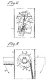
- Figure 1 is a side view, partly in section, illustrating that part of the lock relevant to the present invention;
- Figure 2 is a partial sectional view taken on the line II-II in Figure 1; and
- Figure 3 is a partial sectional view taken on the line III-III in Figure 1.
- The drawings illustrate part of a lock according to the invention which is intended to be fitted to the outside of a door for example, in which there is mounted a conventional lock case incorporating at least one lock bolt. The illustrated lock part relevant to the concept of the invention comprises a
housing 1 which is intended to be mounted on the outside of thedoor 2, shown only schematically in the drawings, centrally of the lock case (not shown in detail) fitted in the door and incorporating at least one lock bolt for locking said door. In the illustrated embodiment, theupper part 1a of thehousing 1 is adapted to enable it to receive amagnetic card 3, and incorporates the requisite electrical components and circuits for reading information registered on the card and for generating an electric lock- release signal upon receiving amagnetic card 3 intended therefor. The arrangement for generating this electrical lock-release signal may have any suitable form, and may comprise the arrangement described and illustrated in European Patent Application No. 84850102-9, for example. Other arrangements may be used for this purpose, however, for example a button array or the like with which a lockrelease code number can be inserted, to give rise to the aforesaid lock-release signal. - Rotatably mounted in the forward wall lb of the
housing 1 is a knob 4 or like device. Ashaft 5 associated with the lock case (not shown in detail) is rotatably journalled in therear wall 1c of thehousing 1 facing thedoor 2, such that the axis of rotation of the shaft is coaxial with the axis of rotation of the knob 4. Theshaft 5 associated with the lock case is arranged to retract the lock bolt to its door-release position upon rotation of theshaft 5 in a conventional manner. Asleeve 6 is suitably journalled for rotation in the wall Ic and extended through therearwati 1c of the housing, this sleeve being provided with, for example, a square hole into which theshaft 5 associated with the lock case projects, said shaft being similarly of square cross-section. - Arranged between the knob 4 and the
sleeve 6 is an electrically actuable coupling arrangement which normally takes a disengaged mode, such that no connection exists between the knob 4 and thesleeve 6, therewith rendering it impossible to retract the lock bolt with the aid of the knob 4, but which can be actuated by means of an electric lock-release signal in a manner to connect the knob 4 with thesleeve 6, therewith enabling thesleeve 6, and also theshaft 5, to be rotated by means of the knob 4, to release the lock. - In the illustrated embodiment of the-invention, the electrically actuable coupling arrangement includes a first coupling element in the form of a plate 7 which is non-rotatably mounted on the inner end of the knob 4 and which is provided around its periphery with at least one tooth or
shoulder 7a, and a second coupling element in the form of a bracket orholder 8 which is arranged on the inner end of thesleeve 6 and in which ahook 9 is pivotably mounted. The plate 7 is biased by aspring 10, which normally holds the plate 7 and therewith the knob 4 inthe position shown in full lines in Figure 3. Rotation of the plate 7 and the knob 4 in a clockwise direction, as seen in Figure 3, is limited by a stationary abutment peg 11, against which anabutment surface 12 on the plate 7 engages. Thepivotable hook 9 on thebracket 8 is spring-biased in a counter clockwise direction, as illustrated in Figure 1, and is normally held in the outwardly swung position illustrated in full lines in Figures 1 and 2. In this outwardly swung position, thehook 9 lies outside the path moved by the tooth orshoulder 7a on the plate 7 when the knob 4, is pressed down or turned, and hence the rotational movement of the knob 4 cannot be transmitted to thesleeve 6 and therewith theshaft 5 of the lock case. Consequently, it is impossible in this position to release the lock by turning or depressing the knob 4. Neither will force exerted on the knob 4 in an attempt to force the lock be transmitted to thejtock mechanism, and is thus unable to damage the same. If, on the other hand, thesprung hook 9 is swung to the inwardly swung position illustrated in chain lines in Figures 1 and 3, the hook will lie in the movement path of the tooth orshoulder 7a on the plate 7, and when the knob 4 is rotated or depressed in the direction shown byarrow 13 in Figure 3, thehook 9, and therewith thebracket 8, thesleeve 6 and theshaft 5 of the lock case, will be entrained by the rotary movement of the knob 4, in a manner to retract the lock bolt to its lock- release position, enabling the door to be opened. - This inward swinging of the
hook 9 so as to enable the lock to be released by means of the knob 4 in the aforedescribed manner is effected through the agency of an electric lock-release signal. In the illustrated embodiment of the invention this electric lock-release signal starts anelectric motor 14 which drives, overgear drive 15, ashaft 16 on which an eccentric 17 and acam plate 18 are mounted. Thecam plate 18 acts upon amicroswitch 22 in a manner such that when themotor 14 is started from the position illustrated in Figure 1, through the agency of an electric lock- release signal, theshaft 16 together with the eccentric 17 and thecam plate 18 are rotated through one half revolution, whereupon the rotary movement is stopped by action of themicroswitch 22. Subsequent to a given, predetermined time delay, which may be determined by means of electrical circuits in the electrical assembly mounted in thepart 1a of thehousing 1 themotor 14 is re-started and rotates theshaft 16, the eccentric 17 and thecam plate 18 through a further half revolution, to the position illustrated in full lines in Figure 1, in which position the motor is again stopped by action of themicroswitch 22. - The
pivotable hook 9 is connected to the eccentric 17 on theshaft 16 by means of a link mechanism incorporating twolink arms link arm 19, which in the illustrated embodiment has the form of a relatively rigid metal wire, is rigidly attached at one end to thehook 9 eccentrically in relation to the pivot axis of the hook. Theother link arm 20, which in the illustrated embodiment comprises a slightly springy metal wire, has the shape of a hairpin and is pivotally mounted on astationary peg 21, in a manner such that the two legs of the hairpin-shaped link arm 20 lie against respective opposite sides of the eccentric 17. The pivotal connecting point between the twolink arms sleeve 6. As will best be seen from Figures 1 and 3, the connecting joint has the form of a circularannular eye 20a on thelink arm 20 and aneye 19a on thelink arm 19, theeye 19a being freely movable around thecircular eye 20a on thelink arm 20. Theannular eye 20a on thelink arm 20 is located substantially concentrically in relation to the common axis of rotation of the knob 4 and thesleeve 6. It will be seen that when theshaft 16 and eccentric 17 are rotated through one half revolution by themotor 14, through the agency of an electric lock-release signal in the aforedescribed manner, thehook 9 will be swung by the action of thelink mechanism sleeve 6, and therewith theshaft 5 of the lock case, can be rotated so as to retract the lock bolt, by depressing or rotating the knob 4. When themotor 14 rotates theshaft 16 and the eccentric 17 through a further half revolution, subsequent to a given predetermined time delay, thelink mechanism hook 9, will return to the position shown infull lines in Figure 1, so as to disengage thesleeve 6, and therewith the lock-case shaft 5, from the knob 4. The lock bolt in the lock case is therewith returned to its outwardly projecting, door-locking position in a conventional manner, under the action of a spring means arranged in the lock case. This particular construction of the pivot between the twolink arms bracket 8, and therewith thehook 9 carried thereby, about the common rotational axis of thesleeve 6 and the knob 4. Because thelink arm 20 co-acting with the eccentric 17 is sprung, theelectric motor 14 is able to continue to rotate through one half revolution when manipulating the lock between a locking and releasing position in the aforedescribed manner, even though, for some reason or other, mechanical locking should occur between thehook 9 and the plate 7 in a manner to prevent thehook 9 from being swung in the manner intended. Due to the fact that themotor 14 will rotate in such cases through one half revolution and be automatically stopped by themicroswitch 22, overloading of and damage to the motor is avoided. - When the knob or corresponding device (not shown in detail in the drawings) located on the other side of the
door 2 is connected directly to theshaft 5 of the lock case, it will be seen that the door can be opened from the inside without requiring the presence of an electric lock-release signal. If, on the other hand, the door is to be opened both from the outside and from the inside of the door solely through the action of an electric lock-release signal, a coupling arrangement of the aforedescribed and illustrated kind actuable by said lock-release signal is also arranged on the inside of the door. - The lock illustrated in full lines in the drawing is constructed and mounted for a righthand door. In order to allow the lock to be used also for a lefthand hung door, the knob 4 can be mounted in the manner shown in chain lines in Figure 3, while at the same time reversing the plate 7 and mounting it on the knob in the position shown in chain lines in Figure 3. In conjunction herewith the
spring 10 is also reversed, so that it strives to rotate the plate 7, and therewith the knob 4, in a counter clock-wise direction in Figure 3. As will be seen from Figure 3, the plate 7 is also able to co-act with thehook 9 on thebracket 8 in this new position, in the same manner-as that aforedescribed. - It will be seen that a lock according to the invention can be constructed in various ways over and above that described by way of example in the aforegoing. For example, the electrically actuable coupling arrangement between the knob or like device and the lock-case shaft determining the position of the lock bolt can have,various mutually different forms. In this respect, the electrical operating means need not necessaíÍíy comprise an electric rotatable motor, but may have the form of solenoid or some other electrical operating means. A rotatable motor, however, has the advantage that it takes current only while it is rotating, and hence the total current consumption of the lock is very small.
Claims (7)
Priority Applications (1)
| Application Number | Priority Date | Filing Date | Title |
|---|---|---|---|
| AT85850242T ATE38699T1 (en) | 1984-08-01 | 1985-07-19 | ELECTRICALLY OPERATED LOCK. |
Applications Claiming Priority (2)
| Application Number | Priority Date | Filing Date | Title |
|---|---|---|---|
| SE8403947A SE442420B (en) | 1984-08-01 | 1984-08-01 | LAS |
| SE8403947 | 1984-08-01 |
Publications (2)
| Publication Number | Publication Date |
|---|---|
| EP0172796A1 EP0172796A1 (en) | 1986-02-26 |
| EP0172796B1 true EP0172796B1 (en) | 1988-11-17 |
Family
ID=20356641
Family Applications (1)
| Application Number | Title | Priority Date | Filing Date |
|---|---|---|---|
| EP85850242A Expired EP0172796B1 (en) | 1984-08-01 | 1985-07-19 | Electrically activated lock |
Country Status (5)
| Country | Link |
|---|---|
| US (1) | US4671087A (en) |
| EP (1) | EP0172796B1 (en) |
| AT (1) | ATE38699T1 (en) |
| DE (1) | DE3566287D1 (en) |
| SE (1) | SE442420B (en) |
Cited By (2)
| Publication number | Priority date | Publication date | Assignee | Title |
|---|---|---|---|---|
| EP2397627A2 (en) | 2010-06-16 | 2011-12-21 | DOM Sicherheitstechnik GmbH & Co. KG | Device for coupling and decoupling an external door handle |
| DE10319185B4 (en) * | 2003-04-29 | 2015-05-13 | Gantner Electronic Gmbh | Electromechanical hardware lock |
Families Citing this family (37)
| Publication number | Priority date | Publication date | Assignee | Title |
|---|---|---|---|---|
| FR2591265B1 (en) * | 1985-12-11 | 1988-03-25 | Llort Oscar | ELECTRICALLY CONTROLLED ARM LOCK USING AN ELECTROMAGNET |
| GB8622120D0 (en) * | 1986-09-13 | 1986-10-22 | Chubb & Sons Lock & Safe Co | Locking mechanisms |
| US4854143A (en) * | 1987-08-07 | 1989-08-08 | Intelock Corporation | Bolt assembly and method |
| FR2628471A1 (en) * | 1988-03-09 | 1989-09-15 | Werke Gestion Securit | Electronically operated door lock - includes transmitter in lock interrogating key circuit before releasing mechanism |
| GB8827906D0 (en) * | 1988-11-30 | 1989-01-05 | Yale Security Prod Ltd | Electromagnetically activated mechanisms |
| GB9013495D0 (en) * | 1990-06-16 | 1990-08-08 | P E D Limited | Solenoid latching system |
| US5018375A (en) * | 1990-09-18 | 1991-05-28 | Yale Security Inc. | Lockset having electric means for disabling and enabling the outer handle |
| FR2674278B1 (en) * | 1991-03-21 | 1995-10-06 | Vachette Sa | CONTROL DEVICE FOR A LOCK AND LOCK EQUIPPED WITH SUCH A DEVICE. |
| CA2071577A1 (en) * | 1991-06-21 | 1992-12-22 | Gerald L. Dawson | Electronic combination lock with high security features |
| JPH06229155A (en) * | 1992-01-13 | 1994-08-16 | C & M Technology Inc | Security lock mechanism |
| US5592838A (en) * | 1992-02-20 | 1997-01-14 | Mas-Hamilton Group | Anti-attack interlocks for a combination lock mechanism |
| FR2697568B1 (en) * | 1992-11-02 | 1995-02-03 | Souza Patrick De | Electric trigger lock. |
| FR2699376B1 (en) * | 1992-12-22 | 1995-03-17 | Samsonite Corp | Locking device for a closing mechanism for luggage. |
| US5421178A (en) * | 1993-01-19 | 1995-06-06 | Best Lock Corporation | Motorized lock actuator for cylindrical lockset |
| US5474348A (en) * | 1993-08-24 | 1995-12-12 | Best Lock Corporation | Motorized actuator for mortise lockset |
| US5511838A (en) * | 1994-02-14 | 1996-04-30 | General Motors Corporation | Remote latch release disabling device |
| DE29603652U1 (en) * | 1996-02-28 | 1997-06-26 | Hewi Heinrich Wilke Gmbh, 34454 Arolsen | Fitting for a lock |
| FR2747149B1 (en) * | 1996-04-05 | 1998-06-12 | Fontaine Sa | ELECTRICAL LOCK / UNLOCK CONTROL DEVICE HAVING ANTI-PANIC FUNCTION AND ANTI-PANIC LOCKS EQUIPPED WITH SUCH A DEVICE |
| NO313761B1 (en) * | 1996-06-13 | 2002-11-25 | Vingcard As | Device for locking, especially an electromagnetic locking unit |
| US5946955A (en) * | 1997-04-30 | 1999-09-07 | Stephen J. Suggs | Door latch/lock control |
| US5884515A (en) * | 1997-09-24 | 1999-03-23 | Ilco Unican Corp. | Electromagnetic clutch for electronic locks |
| FR2776696B1 (en) * | 1998-03-26 | 2000-11-24 | Frederic Imbert | INTELLIGENT SELF-CONTAINED SYSTEM FOR CONTROLLING THE OPENING OF A DOOR EQUIPPED WITH A STANDARD LOCK |
| AUPP400798A0 (en) * | 1998-06-11 | 1998-07-02 | Lockwood Security Products Pty Limited | Electrically controlled lock |
| US6101856A (en) * | 1998-12-14 | 2000-08-15 | Sargent Manufacturing Company | Free-wheeling lever handle lock mechanism |
| US6725693B2 (en) * | 2002-08-30 | 2004-04-27 | Jer Ming Yu | Door lock with a clutch having a cam-styled axle sleeve |
| TWI220910B (en) * | 2003-03-14 | 2004-09-11 | Ez Trend Technology Co Ltd | An electric handle |
| US7069755B2 (en) * | 2003-03-31 | 2006-07-04 | Lies William B | Deadbolt lock with electronic touch-key |
| US7155945B2 (en) * | 2003-10-24 | 2007-01-02 | Talpe Jr Joseph | Lock having a lockable handle shaft |
| KR20060046223A (en) * | 2004-05-27 | 2006-05-17 | 주식회사 유니패스 | Locking device with latch bolt and cylinder separated |
| KR20060106183A (en) * | 2005-04-06 | 2006-10-12 | 김갑식 | Lock device |
| DE102005041081A1 (en) * | 2005-08-30 | 2007-03-01 | D. la Porte Söhne GmbH | Actuation device for door or flap lock, has pusher staying in connection with locking device having remote-controlled electric motor, where locking device is designed as module-like and/or cartridge-like and inserted in handle body |
| US8635893B2 (en) | 2008-09-05 | 2014-01-28 | Lock II, L.L.C. | High security lock |
| CA2731448C (en) * | 2008-09-05 | 2019-01-08 | Lock II, L.L.C. | High security lock |
| US8093986B2 (en) * | 2009-01-20 | 2012-01-10 | Lock II, L.L.C. | Self-powered electronic lock |
| WO2010096034A1 (en) * | 2009-02-20 | 2010-08-26 | Utc Fire & Security Corporation | Low energy clutch for electronic door lock |
| US8677792B2 (en) * | 2009-02-25 | 2014-03-25 | Adams Rite Manufacturing Co. | Electronic door lock apparatus |
| CA2891799C (en) | 2012-12-19 | 2021-05-25 | Lock Ii, Llc | Device and methods for preventing unwanted access to a locked enclosure |
Family Cites Families (20)
| Publication number | Priority date | Publication date | Assignee | Title |
|---|---|---|---|---|
| US540025A (en) * | 1895-05-28 | Controlling mechanism for locks | ||
| US504462A (en) * | 1893-09-05 | Electric lock | ||
| US657853A (en) * | 1900-01-13 | 1900-09-11 | Carleton Electric Company | Electric lock. |
| US947706A (en) * | 1908-12-30 | 1910-01-25 | Adam Leidich | Locking device for automobile starting-cranks. |
| US942605A (en) * | 1909-03-10 | 1909-12-07 | Richeson C Walter | Adjustable door-knob. |
| US1888383A (en) * | 1931-05-14 | 1932-11-22 | Ralph L Holton | Lock |
| US1994104A (en) * | 1932-11-30 | 1935-03-12 | Kebert George | Lock |
| DE961789C (en) * | 1953-08-01 | 1957-04-11 | Robert Fischer | Device for locking the doors of motor vehicles using a locking mechanism electrically controlled by the ignition switch |
| US3655240A (en) * | 1970-07-20 | 1972-04-11 | Essex International Inc | Motor actuated seat back latch release mechanism |
| US3748878A (en) * | 1971-06-07 | 1973-07-31 | Eaton Corp | Door lock electrical control unit |
| SU495432A1 (en) * | 1972-01-03 | 1975-12-15 | Орловский Опытный Завод Научно-Исследовательского Института Автотранспорта | Vehicle door lock |
| CH578670A5 (en) * | 1974-01-07 | 1976-08-13 | Goal Kk | Electric cylinder type lock - has solenoid with locking piece to plunger point, and is guide groove supported |
| FR2300876A1 (en) * | 1975-02-13 | 1976-09-10 | Saunier Duval | ELECTRONIC SECURITY LOCK |
| US4411144A (en) * | 1976-04-16 | 1983-10-25 | Kadex, Inc. | Electronic lock system |
| US4177657A (en) * | 1976-04-16 | 1979-12-11 | Kadex, Inc. | Electronic lock system |
| US4073527A (en) * | 1977-01-12 | 1978-02-14 | Schlage Lock Company | Electrically controlled door lock |
| US4108482A (en) * | 1977-10-20 | 1978-08-22 | Norris Industries | Disengaging spindle locking mechanism |
| FR2437393A1 (en) * | 1978-09-29 | 1980-04-25 | Ugine Kuhlmann | PROCESS FOR THE PREPARATION OF ETHYLENIC CHLORHYDRIN |
| SE428226B (en) * | 1981-04-27 | 1983-06-13 | Bewator Ab | An electrically manoeuvrable device that can latch or release the turning of an axle |
| US4429556A (en) * | 1981-08-13 | 1984-02-07 | Brink Locking Systems, Inc. | Lock mechanism |
-
1984
- 1984-08-01 SE SE8403947A patent/SE442420B/en not_active IP Right Cessation
-
1985
- 1985-07-19 DE DE8585850242T patent/DE3566287D1/en not_active Expired
- 1985-07-19 AT AT85850242T patent/ATE38699T1/en active
- 1985-07-19 EP EP85850242A patent/EP0172796B1/en not_active Expired
- 1985-07-25 US US06/758,974 patent/US4671087A/en not_active Expired - Fee Related
Cited By (3)
| Publication number | Priority date | Publication date | Assignee | Title |
|---|---|---|---|---|
| DE10319185B4 (en) * | 2003-04-29 | 2015-05-13 | Gantner Electronic Gmbh | Electromechanical hardware lock |
| EP2397627A2 (en) | 2010-06-16 | 2011-12-21 | DOM Sicherheitstechnik GmbH & Co. KG | Device for coupling and decoupling an external door handle |
| DE102010017388A1 (en) | 2010-06-16 | 2012-01-12 | Dom Sicherheitstechnik Gmbh & Co Kg | Device for coupling and decoupling an exterior door handle |
Also Published As
| Publication number | Publication date |
|---|---|
| SE8403947D0 (en) | 1984-08-01 |
| ATE38699T1 (en) | 1988-12-15 |
| DE3566287D1 (en) | 1988-12-22 |
| EP0172796A1 (en) | 1986-02-26 |
| SE442420B (en) | 1985-12-23 |
| US4671087A (en) | 1987-06-09 |
Similar Documents
| Publication | Publication Date | Title |
|---|---|---|
| US4671087A (en) | Door lock including electrically actuable coupling arrangement | |
| US5148691A (en) | Electrically and mechanically activatable lock mechanism | |
| US4237711A (en) | Lock mechanism | |
| US4676083A (en) | Locking mechanism with actuator | |
| JP4602569B2 (en) | Gate latch | |
| US5784909A (en) | Control mechanism for tubular locks | |
| US3967479A (en) | Key lock | |
| US3750433A (en) | Mortise lock retract mechanism | |
| US5809812A (en) | Security device for electronic locks | |
| US4073518A (en) | Electrically and manually actuatable door locking structure | |
| CN109812134B (en) | Spring bolt actuating mechanism and have its tool to lock | |
| GB2227049A (en) | Power actuated unit for vehicle central locking system | |
| ES2043245T3 (en) | ELECTRONIC KEY LOCKS. | |
| KR930016631A (en) | Door lock handle for left pull door and right pull door | |
| US5056835A (en) | Latching mechanism for a closure with a disconnectable handle and a sliding catch | |
| JP2001500204A (en) | Lever lock device | |
| US3604229A (en) | Dead bolt and latch door lock | |
| US3304756A (en) | Lock position indicator | |
| HU222937B1 (en) | Electrical control device for locking and unlocking a lock with panic function and panic lock with said device | |
| US3447347A (en) | Pushbutton combination lock | |
| JPH0726809A (en) | Electric lock for sliding door | |
| US20030061849A1 (en) | Motor-driving lock | |
| CN216974435U (en) | Normally open device and door lock thereof | |
| JPS624988Y2 (en) | ||
| CA2297333A1 (en) | Pressure biased clutch mechanism for locks |
Legal Events
| Date | Code | Title | Description |
|---|---|---|---|
| PUAI | Public reference made under article 153(3) epc to a published international application that has entered the european phase |
Free format text: ORIGINAL CODE: 0009012 |
|
| AK | Designated contracting states |
Designated state(s): AT BE CH DE FR GB IT LI NL SE |
|
| 17P | Request for examination filed |
Effective date: 19860626 |
|
| 17Q | First examination report despatched |
Effective date: 19870625 |
|
| RAP3 | Party data changed (applicant data changed or rights of an application transferred) |
Owner name: BESAM SECURITY AKTIEBOLAG |
|
| GRAA | (expected) grant |
Free format text: ORIGINAL CODE: 0009210 |
|
| AK | Designated contracting states |
Kind code of ref document: B1 Designated state(s): AT BE CH DE FR GB IT LI NL SE |
|
| PG25 | Lapsed in a contracting state [announced via postgrant information from national office to epo] |
Ref country code: IT Free format text: LAPSE BECAUSE OF FAILURE TO SUBMIT A TRANSLATION OF THE DESCRIPTION OR TO PAY THE FEE WITHIN THE PRESCRIBED TIME-LIMIT;WARNING: LAPSES OF ITALIAN PATENTS WITH EFFECTIVE DATE BEFORE 2007 MAY HAVE OCCURRED AT ANY TIME BEFORE 2007. THE CORRECT EFFECTIVE DATE MAY BE DIFFERENT FROM THE ONE RECORDED. Effective date: 19881117 Ref country code: SE Effective date: 19881117 Ref country code: NL Effective date: 19881117 Ref country code: CH Effective date: 19881117 Ref country code: BE Effective date: 19881117 Ref country code: LI Effective date: 19881117 Ref country code: AT Effective date: 19881117 |
|
| REF | Corresponds to: |
Ref document number: 38699 Country of ref document: AT Date of ref document: 19881215 Kind code of ref document: T |
|
| REF | Corresponds to: |
Ref document number: 3566287 Country of ref document: DE Date of ref document: 19881222 |
|
| ET | Fr: translation filed | ||
| REG | Reference to a national code |
Ref country code: CH Ref legal event code: PL |
|
| NLV1 | Nl: lapsed or annulled due to failure to fulfill the requirements of art. 29p and 29m of the patents act | ||
| PLBE | No opposition filed within time limit |
Free format text: ORIGINAL CODE: 0009261 |
|
| STAA | Information on the status of an ep patent application or granted ep patent |
Free format text: STATUS: NO OPPOSITION FILED WITHIN TIME LIMIT |
|
| 26N | No opposition filed | ||
| PGFP | Annual fee paid to national office [announced via postgrant information from national office to epo] |
Ref country code: GB Payment date: 19900709 Year of fee payment: 6 |
|
| PGFP | Annual fee paid to national office [announced via postgrant information from national office to epo] |
Ref country code: FR Payment date: 19900717 Year of fee payment: 6 |
|
| PGFP | Annual fee paid to national office [announced via postgrant information from national office to epo] |
Ref country code: DE Payment date: 19900831 Year of fee payment: 6 |
|
| PG25 | Lapsed in a contracting state [announced via postgrant information from national office to epo] |
Ref country code: GB Effective date: 19910719 |
|
| GBPC | Gb: european patent ceased through non-payment of renewal fee | ||
| PG25 | Lapsed in a contracting state [announced via postgrant information from national office to epo] |
Ref country code: FR Effective date: 19920331 |
|
| PG25 | Lapsed in a contracting state [announced via postgrant information from national office to epo] |
Ref country code: DE Effective date: 19920401 |
|
| REG | Reference to a national code |
Ref country code: FR Ref legal event code: ST |