EP0172695B1 - Pickaback bridge spans for use with an inversion-launch bridgelayer - Google Patents
Pickaback bridge spans for use with an inversion-launch bridgelayer Download PDFInfo
- Publication number
- EP0172695B1 EP0172695B1 EP85305526A EP85305526A EP0172695B1 EP 0172695 B1 EP0172695 B1 EP 0172695B1 EP 85305526 A EP85305526 A EP 85305526A EP 85305526 A EP85305526 A EP 85305526A EP 0172695 B1 EP0172695 B1 EP 0172695B1
- Authority
- EP
- European Patent Office
- Prior art keywords
- span
- hook
- bridge
- face
- chord face
- Prior art date
- Legal status (The legal status is an assumption and is not a legal conclusion. Google has not performed a legal analysis and makes no representation as to the accuracy of the status listed.)
- Expired
Links
- 230000008878 coupling Effects 0.000 claims description 27
- 238000010168 coupling process Methods 0.000 claims description 27
- 238000005859 coupling reaction Methods 0.000 claims description 27
- 230000035939 shock Effects 0.000 claims description 3
- 238000000034 method Methods 0.000 claims description 2
- LWZFANDGMFTDAV-BURFUSLBSA-N [(2r)-2-[(2r,3r,4s)-3,4-dihydroxyoxolan-2-yl]-2-hydroxyethyl] dodecanoate Chemical compound CCCCCCCCCCCC(=O)OC[C@@H](O)[C@H]1OC[C@H](O)[C@H]1O LWZFANDGMFTDAV-BURFUSLBSA-N 0.000 description 9
- 235000011067 sorbitan monolaureate Nutrition 0.000 description 9
- 238000011084 recovery Methods 0.000 description 3
- 230000006835 compression Effects 0.000 description 1
- 238000007906 compression Methods 0.000 description 1
- 238000003780 insertion Methods 0.000 description 1
- 230000037431 insertion Effects 0.000 description 1
- 238000012986 modification Methods 0.000 description 1
- 230000004048 modification Effects 0.000 description 1
Images
Classifications
-
- E—FIXED CONSTRUCTIONS
- E01—CONSTRUCTION OF ROADS, RAILWAYS, OR BRIDGES
- E01D—CONSTRUCTION OF BRIDGES, ELEVATED ROADWAYS OR VIADUCTS; ASSEMBLY OF BRIDGES
- E01D15/00—Movable or portable bridges; Floating bridges
- E01D15/12—Portable or sectional bridges
- E01D15/127—Portable or sectional bridges combined with ground-supported vehicles for the transport, handling or placing of such bridges or of sections thereof
Definitions
- This invention relates to bridge spans suitable for carriage two at a time in pick-a-back fashion upon a bridgelayer and for launch singly therefrom, the bridgelayer being of conventional inversion-launch type, ie one in which a span is rotated upwards and over one of its ends.
- Such bridgelayers are commonly used in a scissors-launch mode, in which a first and second bridge span, hinged end to end and folded one on top of the other are conjointly launched by rotation of the hinge end upwards and over the other end of the first span, the second span being simultaneously unfolded from the first by a scissoring action at the hinge, thereby to extend into a bridge of double span length.
- the present invention seeks to provide pick-a-back bridge spans that can be transported in pairs and launched separately from an inversion-launch bridgelayer, do not require the actuation of lever and cable disengagement means in order to separate the bridge spans, and can be deployed without the exposure of personnel.
- a bridge span having a top chord face and an opposed parallel bottom chord face including two first coupling members and two second coupling members located adjacent the top chord face and bottom chord face respectively, each of the second coupling members of a first span being engageable with a first coupling member of an identical second span having its top chord face disposed contiguous with the bottoms chord face of the first span
- inversion-launching of two coupled spans causes rotation of the second span with respect to the first span to an extent limited by one pair of engaged coupling members the rotation causing disengagement of the other pair of coupling members, the said one pair of coupling members then being disengageable by relative longitudinal movement of the first span in relation to the second span.
- the first span is attached with its bottom chord face uppermost in conventional manner to the bridgelayer.
- the second span may then be stacked, also with its bottom chord face uppermost, superjacent the first span and their co-operative first and second coupling members engaged.
- the two spans can then be inverted conjointly by the bridgelayer until the bottom chord face of the second span engages the banks of a gap to be bridged, whereupon the said other coupling members can be disengaged, leaving the second span emplaced and the first span still attached to the bridgelayer for recovery and later deployment elsewhere.
- both the first and the second coupling members on each span permits either span to be used as the first or the second span.
- each first coupling member comprises a pin transversely protrusive from the span along a first axis parallel to the top chord face, each second coupling member being a hook pivotable about a second axis transverse to the span and parallel with the bottom chord face, each hook being engageable with a pin of the superjacent second span.
- the hook is configured to allow horizontal withdrawal of the hook from the pin when the second span has its bottom chord face engaged with the ground and its weight supported thereon, thereby permitting disengagement of the coupling members by the simple expedient of backing off the first span with the bridgelayer.
- first and the second coupling means are each provided in duplicate, symmetrically disposed about the centre line of the length of each span so as to permit launch and retrieval by inversion over either end of the span.
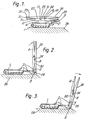
- Figure 1 depicts an inversion-launch bridgelayer 1 having a conventional arrangement of inversion jacks 2 and a launch pad 3, and carrying a first bridge span 4 attached for launch, which span has a bottom chord face 5, a parallel top chord face 6 and two tapering end-ramp top chord faces 7.
- a mirror-imaged pair of first coupling members comprised by hooks 8 and 9 each rotatable about respective axes 10 and 11 are located equidistant from the centre, of the span length, the axes being adjacent and parallel to the bottom chord face 5 with an orientation transverse to the span length.
- a second bridge span 20 having a bottom chord face 21, a parallel top chord face 22, two end-ramp top chord faces 23, and two second coupling members comprised by pins 24 and 25 disposed adjacent and parallel to the top chord face 22 so as to be respectively engagable by the hooks 8 and 9 of the first span 4.
- hook and pin nearest to the end over which the span is to be inverted are interconnected, i.e. the hook 8 and the pin 24 as drawn, the other hook 9 and pin 25 being provided for interconnection when the spans are loaded in the reverse direction upon the bridgelayer.
- Identical pairs of hooks 8 and 9 and pins 24 and 25 are additionally provided (but not shown) adjacent the bottom chord face 21 and the top chord face 6 of the two spans 20 and 4 respectively, so as to permit stacking of the spans in reverse order.
- a second parallel stack of spans 4 and 20 is carried by the bridgelayer 1, (notseen in side view) each lateral pair of spans being cross-connected to provide a twin-trackway span.
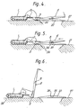
- the bridgelayer 1 In use the bridgelayer 1 is advanced to a bank 26 with the hook 8 and the pin 24 engaged for launch and the hook 9 disposed in transit position (to be discussed later with reference to Figure 7). The two spans are then conjointly inverted by the jacks 2 as shown in Figures 2 to 4 until the span 20 is supported on the bank 26 and the far bank 27, whereupon the bridgelayer 1 is backed away to withdraw the hook and the span 4from the pin 24 (see Figure 5). The span 4 can then be returned to the bridgelayer ( Figure 6) fortransitto another site.
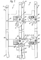
- FIG 7 illustrates detail of the central portion of the two spans 4 and 20 relatively disposed as shown in Figures 1 and 2.
- Each span is comprised by a top chord 40 and a bottom chord 41 which chords respectively define the aforesaid parallel top chord faces 6 and 22 and end-ramp top chord faces 7 and 23, and the bottom chord faces 5 and 21.
- the bottom chord 41 of the span 4 pivotally supports the aforesaid mirror-imaged two hooks 8 and 9 at stub axles 42 and 43 respectively, a similar pair of hooks 44 and 45 being shown attached to the bottom chords 41 of tbe span 20 at stub axles 46 and 47 respectively.
- the top chords 40 of the spans 20 and 4 respectively support the aforesaid pair of pins 24 and 25, and a similar pair of pins 48 and 49.
- Each hook 8, 9, 44 and 45 is comprised by a flat plate having a radiused first bearing edge 50 centered on the inter-span pivot axis 30, and an end capture, second bearing edge 51 perpendicular to the edge 50, and a notch 52 disposed in opposition to the first bearing edge 50.
- Each hook is further provided with two through holes 60 and 61 equidistant from the respective stub axle 42,43, 46 or 47, either one of the holes 60 and 61 being alignable with either one of two sockets 62 and 63 also equidistantly located at either side of the respective stub axle in the bottom chord 41 so as conjointly to permit insertion of a locking pin 64, thereby to secure the hook in any one of three positions, namely, a launch position as illustrated for the hook 8, a transit position as illustrated for the hook 9 and a stowage position as illustrated for both the hooks 44 and 45.
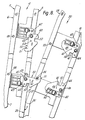
- the disposition of the locking pins 64 shown for all four hooks in Figure 7 is the disposition employed throughout the whole of the transit, launch and recovery sequence illustrated in Figures 1 to 6, the redundant hooks 44 and 45 being locked safely out of the way in the stowage position, active hook 9 being engagable with the pin 25 at the notch 52, and active hook 8 being engagable with the pin 24 at the first bearing edge 50 or at the second bearing edge 51 (see Figure 8).
- the two spans thereafter maintain this relative disposition throughout the remainder of the launch until the weight of the span 20 is supported upon the ground.
- the hook 8 may then be withdrawn from engagement with the pin 24 by backing off the span 4 with the bridgelayer 1 ( Figure 5).
- the span 4 is then returned to the bridgelayer 1 ( Figure 6) for use elsewhere. Retrieval of the span 20 is accomplished by a reverse procedure and may take place from either end.
- This embodiment of the invention is advantageous in requiring no modifications to the bridgelayer, no additional interface with the driver of the bridgelayer and no exposure of personnel throughout deployment and recovery.
Landscapes
- Engineering & Computer Science (AREA)
- Architecture (AREA)
- Civil Engineering (AREA)
- Structural Engineering (AREA)
- Bridges Or Land Bridges (AREA)
Description
- This invention relates to bridge spans suitable for carriage two at a time in pick-a-back fashion upon a bridgelayer and for launch singly therefrom, the bridgelayer being of conventional inversion-launch type, ie one in which a span is rotated upwards and over one of its ends. Such bridgelayers are commonly used in a scissors-launch mode, in which a first and second bridge span, hinged end to end and folded one on top of the other are conjointly launched by rotation of the hinge end upwards and over the other end of the first span, the second span being simultaneously unfolded from the first by a scissoring action at the hinge, thereby to extend into a bridge of double span length.
- When gaps in a terrain of interest are small enough to be bridged by a single span length, inversion-launch bridgelayers capable of carrying a double span for scissors launch are frequently used to carry and launch a single span only. This is clearly an inefficient use of resources when the bridgelayer is capable of transporting two separate spans one on top of the other. Patent specification DE 3,205,563 (Porsche) addresses the problem of individually launching one of two bridge spans from a bridgelayer. The Porsche bridgelayer is connected to the first bridge span to be launched with the second bridge span loaded on top of and connected to the first span, the two spans being interconnected by engagement means. Launching is effected by translation of the two spans over the gap to be bridged. As the first span is lowered into contact with the ground, levers are deflected which decouple the engagement means interconnecting the two spans. When the first span haa been disconnected from the bridgelayer and the second span connected to it, the second span can be reloaded onto the bridgelayer for subsequent deployment. "Sol- dat und Technik", Vol 17,.
No 7, 1974, pages 360-372 relates to the laying of bridges but does not address the problem of the sequential launching of the separate bridge spans from a single bridgelayer. - The present invention seeks to provide pick-a-back bridge spans that can be transported in pairs and launched separately from an inversion-launch bridgelayer, do not require the actuation of lever and cable disengagement means in order to separate the bridge spans, and can be deployed without the exposure of personnel.
- In accordance with the present invention a bridge span having a top chord face and an opposed parallel bottom chord face including two first coupling members and two second coupling members located adjacent the top chord face and bottom chord face respectively, each of the second coupling members of a first span being engageable with a first coupling member of an identical second span having its top chord face disposed contiguous with the bottoms chord face of the first span is characterised in that inversion-launching of two coupled spans causes rotation of the second span with respect to the first span to an extent limited by one pair of engaged coupling members the rotation causing disengagement of the other pair of coupling members, the said one pair of coupling members then being disengageable by relative longitudinal movement of the first span in relation to the second span.
- When two of the said bridge spans are to be carried pick-a-back and separately launched by an inversion-launch bridgelayer, the first span is attached with its bottom chord face uppermost in conventional manner to the bridgelayer. The second span may then be stacked, also with its bottom chord face uppermost, superjacent the first span and their co-operative first and second coupling members engaged. The two spans can then be inverted conjointly by the bridgelayer until the bottom chord face of the second span engages the banks of a gap to be bridged, whereupon the said other coupling members can be disengaged, leaving the second span emplaced and the first span still attached to the bridgelayer for recovery and later deployment elsewhere.
- The provision of both the first and the second coupling members on each span permits either span to be used as the first or the second span.
- Preferably each first coupling member comprises a pin transversely protrusive from the span along a first axis parallel to the top chord face, each second coupling member being a hook pivotable about a second axis transverse to the span and parallel with the bottom chord face, each hook being engageable with a pin of the superjacent second span.
- Conveniently, the hook is configured to allow horizontal withdrawal of the hook from the pin when the second span has its bottom chord face engaged with the ground and its weight supported thereon, thereby permitting disengagement of the coupling members by the simple expedient of backing off the first span with the bridgelayer.
- Preferably the first and the second coupling means are each provided in duplicate, symmetrically disposed about the centre line of the length of each span so as to permit launch and retrieval by inversion over either end of the span.
- An embodiment of the invention will now be described by way of example only, with reference to the accompanying drawings of which
- Figures 1 to 6 are diagrammatic side views of a bridgelayer carrying two bridge spans pick-a-back, sequentially illustrating launch of the top one of the spans, and
- Figures 7 and 8 are detailed views of a coupling member arrangement suitable for the same two spans, and drawn in the relative span dispositions of Figure 2 and Figure 3 respectively.
- Figure 1 depicts an inversion-launch bridgelayer 1 having a conventional arrangement of inversion jacks 2 and a
launch pad 3, and carrying a first bridge span 4 attached for launch, which span has abottom chord face 5, a paralleltop chord face 6 and two tapering end-ramptop chord faces 7. A mirror-imaged pair of first coupling members comprised byhooks bottom chord face 5 with an orientation transverse to the span length. - Superimposed on the span 4 is a
second bridge span 20 having abottom chord face 21, a paralleltop chord face 22, two end-ramp top chord faces 23, and two second coupling members comprised bypins top chord face 22 so as to be respectively engagable by thehooks - For launch purposes, only the hook and pin nearest to the end over which the span is to be inverted are interconnected, i.e. the
hook 8 and thepin 24 as drawn, theother hook 9 andpin 25 being provided for interconnection when the spans are loaded in the reverse direction upon the bridgelayer. Identical pairs ofhooks pins bottom chord face 21 and thetop chord face 6 of the twospans 20 and 4 respectively, so as to permit stacking of the spans in reverse order. - A second parallel stack of
spans 4 and 20 is carried by the bridgelayer 1, (notseen in side view) each lateral pair of spans being cross-connected to provide a twin-trackway span. - In use the bridgelayer 1 is advanced to a
bank 26 with thehook 8 and thepin 24 engaged for launch and thehook 9 disposed in transit position (to be discussed later with reference to Figure 7). The two spans are then conjointly inverted by the jacks 2 as shown in Figures 2 to 4 until thespan 20 is supported on thebank 26 and the farbank 27, whereupon the bridgelayer 1 is backed away to withdraw the hook and the span 4from the pin 24 (see Figure 5). The span 4 can then be returned to the bridgelayer (Figure 6) fortransitto another site. - It will be seen from Figure 3 that once the conjoint spans have been rotated beyond the vertical, the
span 20 pivots against the span 4 about an inter-span pivot axis comprised by abearing edge 30 defined by the transverse line of intersection of thetop chord face 22 and the end-ramptop chord face 23, until theface 23 of thespan 20 engages thebottom chord face 5 of tbe span 4, thereby permitting bothspans 4 and 20 to pivot against thelaunch pad 3 for the remainder of the launch. The detailed arrangements of thehooks pins - Figure 7 illustrates detail of the central portion of the two
spans 4 and 20 relatively disposed as shown in Figures 1 and 2. Each span is comprised by atop chord 40 and abottom chord 41 which chords respectively define the aforesaid paralleltop chord faces - The
bottom chord 41 of the span 4 pivotally supports the aforesaid mirror-imaged twohooks stub axles hooks bottom chords 41 oftbe span 20 atstub axles top chords 40 of thespans 20 and 4 respectively support the aforesaid pair ofpins pins - Each
hook edge 50 centered on theinter-span pivot axis 30, and an end capture, second bearingedge 51 perpendicular to theedge 50, and anotch 52 disposed in opposition to the first bearingedge 50. Each hook is further provided with two throughholes respective stub axle holes sockets bottom chord 41 so as conjointly to permit insertion of alocking pin 64, thereby to secure the hook in any one of three positions, namely, a launch position as illustrated for thehook 8, a transit position as illustrated for thehook 9 and a stowage position as illustrated for both thehooks - The disposition of the
locking pins 64 shown for all four hooks in Figure 7 is the disposition employed throughout the whole of the transit, launch and recovery sequence illustrated in Figures 1 to 6, theredundant hooks active hook 9 being engagable with thepin 25 at thenotch 52, andactive hook 8 being engagable with thepin 24 at the first bearingedge 50 or at the second bearing edge 51 (see Figure 8). - The specific engagements of the
hooks hook 9 preventing relative longitudinal movement of the two spans, and thehook 8 bearing the load of thespan 20 via thepin 24 once inversion has commenced. As soon as the conjoint spans have been rotated beyond the vertical, as shown in Figures 3 and 8, thespan 20 pivots about thebearing edge 30 until its end-ramptop chord face 23 engages with thebottom chord face 5 of the span 4, thepin 25 disengaging from thenotch 52 of thehook 9 and thepin 24 sliding outwardly along the first bearingedge 50 of thehook 8 to come to rest against the end-capture, second bearing edge 51 (see Figure 8). The shock of engagement between thefaces pin 24, is absorbed by a stack ofdisc springs 65 compressible between thehook 8 and the span 4, thehole 60 in thehook 8 being of sufficently larger diameter than thelocking pin 64 to allow freedom for this compression. - The two spans thereafter maintain this relative disposition throughout the remainder of the launch until the weight of the
span 20 is supported upon the ground. Thehook 8 may then be withdrawn from engagement with thepin 24 by backing off the span 4 with the bridgelayer 1 (Figure 5). - The span 4 is then returned to the bridgelayer 1 (Figure 6) for use elsewhere. Retrieval of the
span 20 is accomplished by a reverse procedure and may take place from either end. - This embodiment of the invention is advantageous in requiring no modifications to the bridgelayer, no additional interface with the driver of the bridgelayer and no exposure of personnel throughout deployment and recovery.
Claims (9)
Applications Claiming Priority (2)
| Application Number | Priority Date | Filing Date | Title |
|---|---|---|---|
| GB848421616A GB8421616D0 (en) | 1984-08-24 | 1984-08-24 | Pickaback bridge spans |
| GB8421616 | 1984-08-24 |
Publications (3)
| Publication Number | Publication Date |
|---|---|
| EP0172695A2 EP0172695A2 (en) | 1986-02-26 |
| EP0172695A3 EP0172695A3 (en) | 1987-04-15 |
| EP0172695B1 true EP0172695B1 (en) | 1990-02-07 |
Family
ID=10565834
Family Applications (1)
| Application Number | Title | Priority Date | Filing Date |
|---|---|---|---|
| EP85305526A Expired EP0172695B1 (en) | 1984-08-24 | 1985-08-02 | Pickaback bridge spans for use with an inversion-launch bridgelayer |
Country Status (4)
| Country | Link |
|---|---|
| US (1) | US4649587A (en) |
| EP (1) | EP0172695B1 (en) |
| DE (1) | DE3575963D1 (en) |
| GB (1) | GB8421616D0 (en) |
Cited By (3)
| Publication number | Priority date | Publication date | Assignee | Title |
|---|---|---|---|---|
| EP1584748A2 (en) | 2004-04-07 | 2005-10-12 | Rheinmetall Landsysteme GmbH | Bridge laying arrangement |
| EP1584749A2 (en) | 2004-04-07 | 2005-10-12 | Rheinmetall Landsysteme GmbH | Bridge-laying unit |
| DE102007001778B3 (en) * | 2007-01-05 | 2008-05-29 | Rheinmetall Landsysteme Gmbh | Bridge laying vehicle, has moving module shifted in displacing position at nose-lateral end of base vehicle, support arranged nose-laterally at base vehicle, where moving module is supported front laterally at support in position |
Families Citing this family (8)
| Publication number | Priority date | Publication date | Assignee | Title |
|---|---|---|---|---|
| DE3604621A1 (en) * | 1986-02-14 | 1987-08-20 | Salzgitter Ag | TRANSPORT VEHICLE FOR BRIDGE PARTS |
| IT1226581B (en) * | 1988-08-02 | 1991-01-24 | Reiter & Crippa Ind S P A | BRIDGE, RAMP AND SIMILAR OF SELF-ASSEMBLING TYPE |
| FR2649426B1 (en) * | 1989-07-06 | 1992-03-20 | Mediterranee Const Navales Ind | BRIDGE SYSTEM FOR VEHICLES TO CROSS BRACES |
| GR1001108B (en) * | 1991-07-03 | 1993-04-28 | Peugeot Talbot Espana S A | Transport vehicle |
| DE102004049969B8 (en) * | 2004-10-14 | 2006-03-23 | Military Mobile Bridges Gmbh | Modular scissor bridge and installation device and method for laying collapsible bridges |
| DE102008007715A1 (en) * | 2008-02-06 | 2009-09-10 | Krauss-Maffei Wegmann Gmbh & Co. Kg | Boom of a bridge laying vehicle and method for moving a boom in a vehicle transport position |
| GB0907749D0 (en) * | 2009-05-06 | 2009-07-22 | Pearson Eng Ltd | Bridge deploying apparatus and bridge transporting vehicle incorporating such apparatus |
| US11001397B2 (en) * | 2019-09-13 | 2021-05-11 | Larry Utt | System and method for a modular ramp |
Family Cites Families (3)
| Publication number | Priority date | Publication date | Assignee | Title |
|---|---|---|---|---|
| US4411036A (en) * | 1980-11-27 | 1983-10-25 | The Secretary Of State For Defence In Her Britannic Majesty's Government Of The United Kingdom Of Great Britain And Northern Ireland | Transportable bridge |
| DE3205563A1 (en) * | 1982-02-17 | 1983-08-25 | Dr.Ing.H.C. F. Porsche Ag, 7000 Stuttgart | Bridge-laying appliance |
| US4510637A (en) * | 1983-03-14 | 1985-04-16 | Lucjan Zlotnicki | Bridge launcher |
-
1984
- 1984-08-24 GB GB848421616A patent/GB8421616D0/en active Pending
-
1985
- 1985-08-02 EP EP85305526A patent/EP0172695B1/en not_active Expired
- 1985-08-02 DE DE8585305526T patent/DE3575963D1/en not_active Expired - Lifetime
- 1985-08-07 US US06/763,259 patent/US4649587A/en not_active Expired - Lifetime
Cited By (6)
| Publication number | Priority date | Publication date | Assignee | Title |
|---|---|---|---|---|
| EP1584748A2 (en) | 2004-04-07 | 2005-10-12 | Rheinmetall Landsysteme GmbH | Bridge laying arrangement |
| EP1584749A2 (en) | 2004-04-07 | 2005-10-12 | Rheinmetall Landsysteme GmbH | Bridge-laying unit |
| DE102004016974A1 (en) * | 2004-04-07 | 2005-11-03 | Rheinmetall Landsysteme Gmbh | Bridge-laying unit |
| DE102004016983A1 (en) * | 2004-04-07 | 2005-11-17 | Rheinmetall Landsysteme Gmbh | Bridge laying device |
| DE102004016983B4 (en) * | 2004-04-07 | 2006-01-19 | Rheinmetall Landsysteme Gmbh | Bridge laying device |
| DE102007001778B3 (en) * | 2007-01-05 | 2008-05-29 | Rheinmetall Landsysteme Gmbh | Bridge laying vehicle, has moving module shifted in displacing position at nose-lateral end of base vehicle, support arranged nose-laterally at base vehicle, where moving module is supported front laterally at support in position |
Also Published As
| Publication number | Publication date |
|---|---|
| GB8421616D0 (en) | 1984-09-26 |
| EP0172695A3 (en) | 1987-04-15 |
| DE3575963D1 (en) | 1990-03-15 |
| EP0172695A2 (en) | 1986-02-26 |
| US4649587A (en) | 1987-03-17 |
Similar Documents
| Publication | Publication Date | Title |
|---|---|---|
| EP0172695B1 (en) | Pickaback bridge spans for use with an inversion-launch bridgelayer | |
| US6284967B1 (en) | Solar generator with foldable panels especially for a spacecraft | |
| US4252504A (en) | Helicopter blade folding system | |
| KR101895081B1 (en) | Semi-levered landing gear and associated method | |
| US5682005A (en) | Missile container support rack | |
| US4392623A (en) | Fused connection adapted to fail under different overloads acting in different directions | |
| US5419657A (en) | Method and apparatus for transferring a structure from a jack-up rig to a fixed platform | |
| US4635311A (en) | Military tactical bridge system, method and foldable modules | |
| US20010037538A1 (en) | Automotive, self-locking and damping articulated joint and articulation equipped with same | |
| JP6623004B2 (en) | Deployable mast with spontaneous autonomous deployment and satellite with at least one mast of this kind | |
| EP0433356B1 (en) | Folding transportable bridge | |
| JP2006517487A (en) | Solar panel hinged assembly and spacecraft | |
| US20160289904A1 (en) | Road-bridge module and bridge construction method | |
| US5117525A (en) | Take-apart drive-over bridge with cantilevers between its drive-overs | |
| JP2012526213A (en) | Improved temporary bridge | |
| JP2012526213A5 (en) | ||
| US20100112876A1 (en) | Amphibious vehicle for breaching a water-filled opening | |
| US4411036A (en) | Transportable bridge | |
| EP0185071B1 (en) | Bridge transporting and launching trailer and method | |
| US4747566A (en) | Apparatus for partially unfolding solar collectors | |
| US4587526A (en) | Latching mechanism for deployable/re-stowable columns useful in satellite construction | |
| US5267424A (en) | Module for an articulated stowable and deployable mast | |
| CN113336080A (en) | Hoisting device and hoisting method for carrier rocket | |
| US4962556A (en) | Lightweight, collapsible bridge module, and system with deployment and retrieval trailer | |
| GB2088447A (en) | Transportable bridge |
Legal Events
| Date | Code | Title | Description |
|---|---|---|---|
| PUAI | Public reference made under article 153(3) epc to a published international application that has entered the european phase |
Free format text: ORIGINAL CODE: 0009012 |
|
| AK | Designated contracting states |
Designated state(s): DE FR GB |
|
| PUAL | Search report despatched |
Free format text: ORIGINAL CODE: 0009013 |
|
| AK | Designated contracting states |
Kind code of ref document: A3 Designated state(s): DE FR GB |
|
| 17P | Request for examination filed |
Effective date: 19871005 |
|
| 17Q | First examination report despatched |
Effective date: 19890213 |
|
| GRAA | (expected) grant |
Free format text: ORIGINAL CODE: 0009210 |
|
| AK | Designated contracting states |
Kind code of ref document: B1 Designated state(s): DE FR GB |
|
| ET | Fr: translation filed | ||
| REF | Corresponds to: |
Ref document number: 3575963 Country of ref document: DE Date of ref document: 19900315 |
|
| PLBE | No opposition filed within time limit |
Free format text: ORIGINAL CODE: 0009261 |
|
| STAA | Information on the status of an ep patent application or granted ep patent |
Free format text: STATUS: NO OPPOSITION FILED WITHIN TIME LIMIT |
|
| 26N | No opposition filed | ||
| REG | Reference to a national code |
Ref country code: GB Ref legal event code: 732E |
|
| REG | Reference to a national code |
Ref country code: GB Ref legal event code: IF02 |
|
| REG | Reference to a national code |
Ref country code: FR Ref legal event code: TP |
|
| PGFP | Annual fee paid to national office [announced via postgrant information from national office to epo] |
Ref country code: FR Payment date: 20040708 Year of fee payment: 20 |
|
| PGFP | Annual fee paid to national office [announced via postgrant information from national office to epo] |
Ref country code: GB Payment date: 20040712 Year of fee payment: 20 |
|
| PGFP | Annual fee paid to national office [announced via postgrant information from national office to epo] |
Ref country code: DE Payment date: 20040716 Year of fee payment: 20 |
|
| PG25 | Lapsed in a contracting state [announced via postgrant information from national office to epo] |
Ref country code: GB Free format text: LAPSE BECAUSE OF EXPIRATION OF PROTECTION Effective date: 20050801 |
|
| REG | Reference to a national code |
Ref country code: GB Ref legal event code: PE20 |