EP0171247A2 - Control valve for vehicle power steering systems - Google Patents
Control valve for vehicle power steering systems Download PDFInfo
- Publication number
- EP0171247A2 EP0171247A2 EP85305390A EP85305390A EP0171247A2 EP 0171247 A2 EP0171247 A2 EP 0171247A2 EP 85305390 A EP85305390 A EP 85305390A EP 85305390 A EP85305390 A EP 85305390A EP 0171247 A2 EP0171247 A2 EP 0171247A2
- Authority
- EP
- European Patent Office
- Prior art keywords
- valve
- sleeve member
- valve core
- sleeve
- control valve
- Prior art date
- Legal status (The legal status is an assumption and is not a legal conclusion. Google has not performed a legal analysis and makes no representation as to the accuracy of the status listed.)
- Granted
Links
Images


Classifications
-
- B—PERFORMING OPERATIONS; TRANSPORTING
- B62—LAND VEHICLES FOR TRAVELLING OTHERWISE THAN ON RAILS
- B62D—MOTOR VEHICLES; TRAILERS
- B62D5/00—Power-assisted or power-driven steering
- B62D5/06—Power-assisted or power-driven steering fluid, i.e. using a pressurised fluid for most or all the force required for steering a vehicle
- B62D5/08—Power-assisted or power-driven steering fluid, i.e. using a pressurised fluid for most or all the force required for steering a vehicle characterised by type of steering valve used
- B62D5/083—Rotary valves
-
- Y—GENERAL TAGGING OF NEW TECHNOLOGICAL DEVELOPMENTS; GENERAL TAGGING OF CROSS-SECTIONAL TECHNOLOGIES SPANNING OVER SEVERAL SECTIONS OF THE IPC; TECHNICAL SUBJECTS COVERED BY FORMER USPC CROSS-REFERENCE ART COLLECTIONS [XRACs] AND DIGESTS
- Y10—TECHNICAL SUBJECTS COVERED BY FORMER USPC
- Y10T—TECHNICAL SUBJECTS COVERED BY FORMER US CLASSIFICATION
- Y10T137/00—Fluid handling
- Y10T137/8593—Systems
- Y10T137/86493—Multi-way valve unit
- Y10T137/86549—Selective reciprocation or rotation
-
- Y—GENERAL TAGGING OF NEW TECHNOLOGICAL DEVELOPMENTS; GENERAL TAGGING OF CROSS-SECTIONAL TECHNOLOGIES SPANNING OVER SEVERAL SECTIONS OF THE IPC; TECHNICAL SUBJECTS COVERED BY FORMER USPC CROSS-REFERENCE ART COLLECTIONS [XRACs] AND DIGESTS
- Y10—TECHNICAL SUBJECTS COVERED BY FORMER USPC
- Y10T—TECHNICAL SUBJECTS COVERED BY FORMER US CLASSIFICATION
- Y10T137/00—Fluid handling
- Y10T137/8593—Systems
- Y10T137/86493—Multi-way valve unit
- Y10T137/86718—Dividing into parallel flow paths with recombining
- Y10T137/86743—Rotary
- Y10T137/86751—Plug
Definitions
- This invention relates to control valves for power assisted steering systems for vehicles, and in particular to control valves for use in systems in which it is deemed desirable to have.the degree of power assistance change with vehicle speed or some other variable related to the mode of operation of the vehicle.
- a power assisted steering system can be characterized as operating under three driving conditions. Firstly during straight ahead driving at medium to high speeds, the power requirements on the steering system are extremely low and the degree of power assistance provided by the steering gear should be correspondingly minimized to permit the feedback of road "feel" from the tyres to the driver. Secondly during medium and high speed passing and cornering maneouvres, a progressive increase in the level of power assistance with driver input torque is desirable. Nevertheless moderate driver input torques should still be maintained in order that the driver can feel adequately the dynamic state of the vehicle. Thirdly, and lastly, during low speed or parking maneouvres, the power requirements on the steering system may be large and the fidelity of the steering system in terms of transmitting road feel is of little importance. Under these circumstances it is generally desirable to offer large degrees of power assistance, thereby minimizing the input torque required to be furnished by the driver.
- a system which provides for better modulation of power assistance with vehicle speed is that disclosed in U.S. Patent 4,438,827 and can be seen to employ a hydraulic reaction type valve.
- the characteristics provided by this system are described in Automotive Engineering, Volume 90, Number 4, April 1982 which shows that the assistance pressure provided by the valve varies in a linear manner when plotted against driver input torque and that the slope of this line is made to vary continuously and smoothly with vehicle speed.
- Each assistance pressure line so defined starts only after some threshold value of input torque is reached, and terminates at some other point where a further increase in input torque would serve no useful function.
- the system is however very complicated and increases the rotational friction of the valve assembly as compared with valves not incorporating the speed sensitive feature.
- the present invention is based on the widely used torsion-bar-centred rotary valve as first disclosed in U.S. Patent 3,022,772 wherein only three principal valve elements are required: a sleeve member incorporating longitudinal grooves in its bore, a valve core relatively rotatable therein also having longitudinal grooves, and a torsion bar.
- a sleeve member incorporating longitudinal grooves in its bore
- a valve core relatively rotatable therein also having longitudinal grooves
- a torsion bar a torsion bar.
- an infinite range of assistance pressure lines similar to those above described in Automotive Engineering, Volume 90, Number 4, April 1982 may be provided but in a simple and low cost rotary valve construction.
- the object of the specific groove edge configuration is to provide an orifice area curve (Figure 6 of that specification) having three principal features: an initial rapid rate of reduction of orifice area for the first part of valve deflection from the centred position, an exponential type further decrease of area up to about 2 degrees, and a final rapid close-off of area.
- a linear-assistance pressure region having a rate of 250 psi/degree is provided ( Figure 5 of that specification).
- a similar linear assistance pressure relationship is provided at some intermediate mode of operation of the valve.
- the valve also provides that the slope of this line can be smoothly and continuously changed from a much lower value of say 0.6 MPa/degree for high speed driving, up to say 20 MPa/degree for parking, the latter resulting in substantially lower steering wheel input torques. The compromise in the valve performance of most power steering gears is thus avoided.
- the essential feature of the present invention lies in the imparting of an axial movement to the sleeve member along the valve core as a function of, for example, vehicle speed. Relative rotation between the sleeve member and the valve core is utilized as in normal valve operation. The changed characteristics of the valve assembly result from a progressive masking of a section of the groove edges of the valve core.
- the orifice area curve provided by the groove edges of a valve core made according to this invention remain substantially that shown in U.S. Patent 3,591,136, although there are some essential differences.
- the "logarithmic scroll” lld is removed from the elongated edges of the valve groove so that these edges now become approximately parallel to the valve core axis.
- the "logarithmic scroll” feature which provides the exponential section of the area curve, is now incorporated in the cross-section of the pocket shown in Figure 3a of that specification.
- the elongated edges are preferably no longer sharp, as viewed in section but are slightly relieved or contoured along at least part of their length.
- the sleeve member When the sleeve member is caused to'move along the valve core it progressively masks the pocket and so proportionately scales down that section of the orifice area curve comprising the "logarithmic scroll" feature and also the final rapid close-off.
- the angle through which the valve elements must be relatively rotated to approach close-off thus changes from a relatively large angle, where the pocket is unmasked, to a much smaller angle when it is fully masked by travel of the sleeve member.
- the angle through which the torsion bar must be twisted is large in the former instance and much smaller in the latter.
- the sleeve member is caused to take up a position which the pocket is substantially unmasked when the vehicle speed is high and to move progressively along the valve core with decreasing vehicle speed until the pocket is fully masked and hence steering efforts are very low, when parking.
- the sleeve is moved along the valve core by a spring secured thereto which acts on the end face of the sleeve member.
- Exhaust oil escaping from the valve elements is caused to act on the annular area of the sleeve member at the end opposite the spring, and by modulating the escape pressure through a suitable valve (which may be located remotely from the steering gear), the sleeve member may be accurately positioned along its travel as a function of a vehicle speed signal.
- a suitable valve which may be located remotely from the steering gear
- the sleeve member may be accurately positioned along its travel as a function of a vehicle speed signal.
- This arrangement has the additional advantage that the orifices within the valve operate against an increasing back pressure when the vehicle is moving slowly, so tending to suppress valve noises which, as is well known, occur in these instances.
- the axial movement of the sleeve member may be effected by either direct mechanical or electro-mechanical means.
- Various signals may be used other than, or in combination with, vehicle speed, for example vehicle lateral acceleration or angular turn of the steering wheel.
- the sleeve member may be positioned via a driver operated control so that a wide range of valve assistance pressure characteristics can be selected manually.
- valve housing 1 is provided with pump inlet and return connections 2 and 3 respectively and right and left hand cylinder connections 4 and 5.
- Steering gear housing 6, to which valve housing 1 is attached, contains the mechanical steering elements, for example, pinion 7, journalled by ball race 8 and provided with seal 9.
- valve core/input shaft 10 sleeve member 11 journalled thereon
- torsion bar 12 This torsion bar is secured by a pin to the valve core at one end and similarly to pinion 7-at the other. It also provides a journal for valve core input shaft 10 by way of a bush as at 14.
- Sleeve member 11 has an annular extension having therein a slot 15 engaging pin 16 extending radially from pinion 7.
- Valve core 10 and sleeve member 11 incorporate in their mating surfaces a plurality of longitudinally extending, blind ended grooves 18 and 18a respectively.
- Sleeve 11 is also provided on its outer periphery with a series of axially spaced circumferential grooves 17 separated by seals, each latter groove being connected by a plurality of radial holes 19 and 19a to the bore of the sleeve.
- Radial holes 20 in valve core 10 connect one or more grooves 18 to the centre hole in the valve whence return oil can flow via ports 21 and 21a to pump return conection 3.
- volute spring 22 which is axially restrained on valve core 10 by groove 23 presses on the end face 24 of sleeve 11 so urging it into contact with the end face 25 of pinion 7.
- Sleeve 11 can be caused to move axially along valve core 10 to the right not withstanding the progressively increasing opposition of volute spring 22.
- the force necessary to so move the sleeve is provided by the difference of oil pressures acting on the annular areas at each end of the sleeve defined by the outer diameter of valve core 10 and internal diameter of housing 1.
- valve 26 can be progressively closed by applying a variable voltage to solenoid 28 so causing the progressive displacement of sleeve 11 to the right in accordance with the variable voltage signal.
- valves operate to direct oil to right and left cylinder ports 4 and 5
- valve groove edges 29 of valve core grooves 18 to improve the modulation of the valve is also a common practice.
- the techniques of featuring the valve groove edges set out in U.S. Patent 3,591,136 are particularly pertinent to the present invention in several respects.
- the featuring is asymetric along the length, with a short pocket 30 configuration at one end and an elongated relatively plain section 31 over the remainder of the length as illustrated in Figure 3.
- Two longitudinal grooves 18a of sleeve member 11 are seen to partially overlap one groove 18 of the valve core.
- the termination of sleeve grooves 18a are illustrated chain dotted as at 32 in the normal position of the sleeve member 11, and in the fully axially displaced position of the latter at 32d.
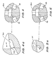
- Figure 4 shows a section of the groove edges as at CC of Figure 3 with an enlarged view of the short pocket section 30 shown in Figure 4a.
- Figure 5 shows a section of the groove edges as at DD of Figure 3 with an enlarged view of the elongated groove edge 31 shown in Figure 5a.
- the orifice areas provided by the two sections of each of the featured grooves are substantially determined by the product of the length of the groove and the effective width which is the shortest distance between the edges of sleeve grooves 18a and of the adjacent edges of valve groove 18, being distances 33 and 34 for the long and short sections respectively. These distances change with relative rotation of sleeve and valve illustrated by the arrows in the respective enlarged views.
- Figure 6 shows a graph with an X axis representing the relative rotation of the sleeve and valve-core edges from a centred position shown as 0 (zero) degrees to say a maximum operating travel of about 4 degrees, and with a Y axis representing individual orifice areas in square millimetres.
- the area curve 37 which terminates on the X axis at point 38, represents the area provided by elongated groove edges 31 as they close from the O degrees or centred position of the valve.
- Area curve 36 which is here plotted below the X axis for convenience, shows the orifice areas provided by the short pocket 30.
- the total area of the orifice at any angle is therefore the sum of the areas expressed by the area curves 36 and 37 and will appear as shown by dotted line 39.
- area curve 39 will be a mirror image about the X axis of area curve 36.
- the area ordinate of curve 39 decreases approximately exponentially with increased relative valve rotation.
- the ratio of area ordinate 40 at 2 degrees to area ordinate 41 at 3 degrees is approximately expressed by the relationship: where alpha is some threshold angle. This characteristic is similar to that provided by the "logarithmic scroll" groove edges of U.S. Patent 3,591,136.
- Line 36 shows the area provided when the sleeve occupies the position shown in Figure 1 and lines 36a, 36b, 36c and 36d show the progressively lesser areas as the sleeve progressively moves to positions 32a, 32b, 32c and 32d of Figure 3.
- FIG. 7 The characteristics of operation of a valve of the type just described are shown in Figure 7.
- the X axis again shows the valve angle but also, at a different scale, the input torque applied by the driver to the steering wheel.
- the two functions are directly related by the stiffness of the torsion bar 12, as is well known. In the case illustrated, 1 degree torsion bar deflection occurs for 2 Nm applied torque.
- assistance pressure lines 43, 43a, 43b, 4-3c and 43d are, over much of their length, substantially straight lines which, extended to the X axis, intersect at the threshold angle alpha.
- This elongated relief also serves to break the flow of oil at high pressure (as when parking) into an elongated but thin jet, a technique well known in the art of steering valve design used to reduce valve noises such as hiss during parking. When this technique is used in simple valves it often enforces a compromise of the valve performance. However, in a valve made according to the present invention this elongated relief determines valve performance only at low vehicle speeds or parking maneouvres where short pocket 30 is masked off.
- damper ring As taught in U.S. Patent specification 3,022,772
- This has the disadvantage of increasing valve hysteresis and therefore reduces road feel which is particularly undesireable at high speeds.
- damper ring 44 is housed in a circumferential groove 35 in valve core 10a and is fed with oil from sleeve groove 18a by a communicating groove 45 only when the sleeve is displaced to its extreme right position as occurs during parking.
- the set linear assistance pressure lines of varying slope which is provided by the preferred embodiment may be replaced by a set of different characteristics each of which is entirely different one to the other.
- the heart of the concept lies in the provision of a family of assistance pressure curves which change progressively from low assistance pressure and high steering efforts at high speeds to high assistance pressure and low steering efforts at low speeds.
- the change from one mode to another occurs without steps or discontinuities, and no compromise in valve responsiveness occurs in the critical low effort zone near the centre region of valve operation.
- the maximum turning rate of the steering gear is not affected, and the frictional losses are minimal.
- the movement of the sleeve axially may be achieved by the solenoid-operated valve described, but, alternatively may be directly mechanically or electromechanically driven.
- a miniature rotary actuator may be located on valve housing 1. This rotary actuator would be provided with a spindle extending inside the valve housing and have teeth thereon which engage a circular rack cut in the periphery of the sleeve member.
Abstract
Description
- This invention relates to control valves for power assisted steering systems for vehicles, and in particular to control valves for use in systems in which it is deemed desirable to have.the degree of power assistance change with vehicle speed or some other variable related to the mode of operation of the vehicle.
- A power assisted steering system can be characterized as operating under three driving conditions. Firstly during straight ahead driving at medium to high speeds, the power requirements on the steering system are extremely low and the degree of power assistance provided by the steering gear should be correspondingly minimized to permit the feedback of road "feel" from the tyres to the driver. Secondly during medium and high speed passing and cornering maneouvres, a progressive increase in the level of power assistance with driver input torque is desirable. Nevertheless moderate driver input torques should still be maintained in order that the driver can feel adequately the dynamic state of the vehicle. Thirdly, and lastly, during low speed or parking maneouvres, the power requirements on the steering system may be large and the fidelity of the steering system in terms of transmitting road feel is of little importance. Under these circumstances it is generally desirable to offer large degrees of power assistance, thereby minimizing the input torque required to be furnished by the driver.
- The demands for optimum valve characteristics during the above three driving conditions conflict. Attempts have been made in the past to avoid the conflicting demands of the first and third driving conditions, namely the need to achieve a low level of assistance for high to medium speed on-center driving while having high levels of assistance for low speed and parking maneouvres, by exploiting the fact that, for most valves, the degree of assistance varies with the flow of oil. For example, in one such widely used system, the power steering pump is caused to reduce the flow of oil as vehicle speed increases. However this adversely affects valve performance in the second driving condition above, namely medium to high speed passing and cornering maneouvres, where progressive valve response is impaired due to the low oil flow. Also, in the event that such a steering maneouvre requires rapid turning of the steering wheel, the lower pump flow may be inadequate, rendering the power assistance momentarily inoperative.
- The most satisfactory method of matching valve performance in all three of the abovementioned conditions is modulating the valve characteristic with vehicle speed. One such speed sensitive valve system designed with this aim in mind is described by F.J. Adams (see S.A.E. Paper 830998, June 6, 1983). This provides a system whereby the valve is held in an inoperative mode by a ball detent arrangement, the effectiveness of which increases with vehicle speed. The ball detent is activated by a separate source of oil under pressure which is communicated via additional grooves and seals to the rotatable valve elements in which the ball detent is housed. This increases the valve friction which is undesirable.
- A system which provides for better modulation of power assistance with vehicle speed is that disclosed in U.S. Patent 4,438,827 and can be seen to employ a hydraulic reaction type valve. The characteristics provided by this system are described in Automotive Engineering, Volume 90,
Number 4, April 1982 which shows that the assistance pressure provided by the valve varies in a linear manner when plotted against driver input torque and that the slope of this line is made to vary continuously and smoothly with vehicle speed. Each assistance pressure line so defined starts only after some threshold value of input torque is reached, and terminates at some other point where a further increase in input torque would serve no useful function. The system is however very complicated and increases the rotational friction of the valve assembly as compared with valves not incorporating the speed sensitive feature. - The present invention is based on the widely used torsion-bar-centred rotary valve as first disclosed in U.S. Patent 3,022,772 wherein only three principal valve elements are required: a sleeve member incorporating longitudinal grooves in its bore, a valve core relatively rotatable therein also having longitudinal grooves, and a torsion bar. According to the present invention, an infinite range of assistance pressure lines similar to those above described in Automotive Engineering, Volume 90,
Number 4, April 1982 may be provided but in a simple and low cost rotary valve construction. - The manner by which a simple three element rotary valve may be made to generate the performance characteristics of hydraulic reaction valves is set out in U.S. Patent 3,591,136. In the latter patent the valve core incorporates grooves having edges featured in a very specific geometrical configuration (Figure 7 of that specification) which includes a "logarithmic scroll" (lld), that provides an exponential area change and therefore a linear increase of assistance pressure with relative rotation of the valve elements. At one end of the groove a pocket (llg) is provided.
- The object of the specific groove edge configuration is to provide an orifice area curve (Figure 6 of that specification) having three principal features: an initial rapid rate of reduction of orifice area for the first part of valve deflection from the centred position, an exponential type further decrease of area up to about 2 degrees, and a final rapid close-off of area. A linear-assistance pressure region having a rate of 250 psi/degree is provided (Figure 5 of that specification).
- In a preferred form of the present invention a similar linear assistance pressure relationship is provided at some intermediate mode of operation of the valve. However, the valve also provides that the slope of this line can be smoothly and continuously changed from a much lower value of say 0.6 MPa/degree for high speed driving, up to say 20 MPa/degree for parking, the latter resulting in substantially lower steering wheel input torques. The compromise in the valve performance of most power steering gears is thus avoided.
- The essential feature of the present invention lies in the imparting of an axial movement to the sleeve member along the valve core as a function of, for example, vehicle speed. Relative rotation between the sleeve member and the valve core is utilized as in normal valve operation. The changed characteristics of the valve assembly result from a progressive masking of a section of the groove edges of the valve core.
- In preferred forms of the invention the orifice area curve provided by the groove edges of a valve core made according to this invention remain substantially that shown in U.S. Patent 3,591,136, although there are some essential differences. Firstly the "logarithmic scroll" lld is removed from the elongated edges of the valve groove so that these edges now become approximately parallel to the valve core axis. The "logarithmic scroll" feature, which provides the exponential section of the area curve, is now incorporated in the cross-section of the pocket shown in Figure 3a of that specification. The elongated edges (now approximately straight) are preferably no longer sharp, as viewed in section but are slightly relieved or contoured along at least part of their length.
- When the sleeve member is caused to'move along the valve core it progressively masks the pocket and so proportionately scales down that section of the orifice area curve comprising the "logarithmic scroll" feature and also the final rapid close-off. The angle through which the valve elements must be relatively rotated to approach close-off thus changes from a relatively large angle, where the pocket is unmasked, to a much smaller angle when it is fully masked by travel of the sleeve member. As a result, the angle through which the torsion bar must be twisted (and hence the effort applied by the driver to the steering wheel rim) is large in the former instance and much smaller in the latter. Hence the sleeve member is caused to take up a position which the pocket is substantially unmasked when the vehicle speed is high and to move progressively along the valve core with decreasing vehicle speed until the pocket is fully masked and hence steering efforts are very low, when parking.
- In one form of the invention, the sleeve is moved along the valve core by a spring secured thereto which acts on the end face of the sleeve member. Exhaust oil escaping from the valve elements is caused to act on the annular area of the sleeve member at the end opposite the spring, and by modulating the escape pressure through a suitable valve (which may be located remotely from the steering gear), the sleeve member may be accurately positioned along its travel as a function of a vehicle speed signal. This arrangement has the additional advantage that the orifices within the valve operate against an increasing back pressure when the vehicle is moving slowly, so tending to suppress valve noises which, as is well known, occur in these instances. Alternatively the axial movement of the sleeve member may be effected by either direct mechanical or electro-mechanical means.
- Various signals may be used other than, or in combination with, vehicle speed, for example vehicle lateral acceleration or angular turn of the steering wheel. Alternatively the sleeve member may be positioned via a driver operated control so that a wide range of valve assistance pressure characteristics can be selected manually.
- One preferred embodiment of the invention is hereinafter described by way of example, with reference to the accompanying drawings.
- Figure 1 is a section through the valve of a steering system made according to the invention;
- Figure 2 is a part-section through AA of Figure 1;
- Figure 3 is a part-view in direction BB of Figure 2;
- Figure 4 is a section through CC of Figure 3;
- Figure 4a is an enlarged version of a portion of Figure 4;
- Figure 5 is a section through DD of Figure 3;
- Figure 5a is an enlarged version of a portion of Figure 5;
- Figure 6 is a graph showing a plot of the orifice area versus relative rotation of the valve elements;
- Figure 7 is a graph showing a plot of the power-assistance pressure versus relative rotation of the valve elements, and also versus the steering input torque applied by the driver to the steering wheel;
- Figure 8 is a scrap view in section of part of Figure 1 showing an alternative version of the valve.
- Referring to Figure 1, valve housing 1 is provided with pump inlet and
return connections hand cylinder connections -
Steering gear housing 6, to which valve housing 1 is attached, contains the mechanical steering elements, for example, pinion 7, journalled byball race 8 and provided with seal 9. - The three main valve elements comprise valve core/
input shaft 10,sleeve member 11 journalled thereon, andtorsion bar 12. This torsion bar is secured by a pin to the valve core at one end and similarly to pinion 7-at the other. It also provides a journal for valvecore input shaft 10 by way of a bush as at 14. -
Sleeve member 11 has an annular extension having therein aslot 15 engagingpin 16 extending radially from pinion 7. -
Valve core 10 andsleeve member 11 incorporate in their mating surfaces a plurality of longitudinally extending, blind endedgrooves Sleeve 11 is also provided on its outer periphery with a series of axially spacedcircumferential grooves 17 separated by seals, each latter groove being connected by a plurality ofradial holes valve core 10 connect one ormore grooves 18 to the centre hole in the valve whence return oil can flow viaports 21 and 21a to pumpreturn conection 3. - In the normal operating condition of the valve illustrated in Figure 1
volute spring 22, which is axially restrained onvalve core 10 bygroove 23 presses on theend face 24 ofsleeve 11 so urging it into contact with theend face 25 of pinion 7.Sleeve 11 can be caused to move axially alongvalve core 10 to the right not withstanding the progressively increasing opposition ofvolute spring 22. The force necessary to so move the sleeve is provided by the difference of oil pressures acting on the annular areas at each end of the sleeve defined by the outer diameter ofvalve core 10 and internal diameter of housing 1. - These pressures are equal when
valve 26 is fully open as illustrated in Figure 1, by reason of the fact that drilledpassages 27 vent the right hand annular area of the sleeve to pumpreturn connection 3.Valve 26 can be progressively closed by applying a variable voltage to solenoid 28 so causing the progressive displacement ofsleeve 11 to the right in accordance with the variable voltage signal. - It will be seen that the radially drilled holes of inlet and
cylinder connections sleeve 11 to slide axially to the right a limited distance without interruption to the flow of oil.Slot 15 also insures that pinion 7 always positively drivessleeve 11 viapin 16. - In Figure 2 it will be seen that, in the neutral position of the valve illustrated, the
longitudinal grooves radial inlet ports 19 and radial return holes 20 in the valve core. - The manner in which the valve operates to direct oil to right and left
cylinder ports valve core grooves 18 to improve the modulation of the valve is also a common practice. - However, the techniques of featuring the valve groove edges set out in U.S. Patent 3,591,136 are particularly pertinent to the present invention in several respects. For example, in contrast to the usual practice, the featuring is asymetric along the length, with a
short pocket 30 configuration at one end and an elongated relativelyplain section 31 over the remainder of the length as illustrated in Figure 3. Twolongitudinal grooves 18a ofsleeve member 11 are seen to partially overlap onegroove 18 of the valve core. The termination ofsleeve grooves 18a are illustrated chain dotted as at 32 in the normal position of thesleeve member 11, and in the fully axially displaced position of the latter at 32d. - Figure 4 shows a section of the groove edges as at CC of Figure 3 with an enlarged view of the
short pocket section 30 shown in Figure 4a. Figure 5 shows a section of the groove edges as at DD of Figure 3 with an enlarged view of theelongated groove edge 31 shown in Figure 5a. - The orifice areas provided by the two sections of each of the featured grooves are substantially determined by the product of the length of the groove and the effective width which is the shortest distance between the edges of
sleeve grooves 18a and of the adjacent edges ofvalve groove 18, beingdistances - Figure 6 shows a graph with an X axis representing the relative rotation of the sleeve and valve-core edges from a centred position shown as 0 (zero) degrees to say a maximum operating travel of about 4 degrees, and with a Y axis representing individual orifice areas in square millimetres.
- The
area curve 37, which terminates on the X axis atpoint 38, represents the area provided by elongated groove edges 31 as they close from the O degrees or centred position of the valve. Area curve 36, which is here plotted below the X axis for convenience, shows the orifice areas provided by theshort pocket 30. - The total area of the orifice at any angle is therefore the sum of the areas expressed by the area curves 36 and 37 and will appear as shown by dotted
line 39. To the right ofpoint 38 wherecurve 37 has reached zero,area curve 39 will be a mirror image about the X axis of area curve 36. In this region the area ordinate ofcurve 39 decreases approximately exponentially with increased relative valve rotation. Thus the ratio of area ordinate 40 at 2 degrees to area ordinate 41 at 3 degrees is approximately expressed by the relationship:
where alpha is some threshold angle. This characteristic is similar to that provided by the "logarithmic scroll" groove edges of U.S. Patent 3,591,136. - Because of the laws which apply to such orifices, as expressed by the approximate equation P = K/A2, it follows that the pressure change between
angles 2 alpha and 3 alpha will increase in proportion to the valve angle above the threshold angle alpha. In this equation P is the pressure restriction provided by an orifice, A is the orifice area in square millimetres, and K is some constant related to the flow of oil. - Line 36 shows the area provided when the sleeve occupies the position shown in Figure 1 and
lines positions - Now the area provided by
elongated edges 31 as represented byarea curve 37 is unaffected by the axial movement of the sleeve. It follows that thesum area curve 39 diminishes in vertical ordinate and eventually becomes coincident with line 37 (although this progressive change is not illustrated in Figure 6) and that the angle at which area close-off occurs indicated bypoint 42 at about 4 degrees progressively reduces to the angle indicated bypoint 42d at about 1 degree. It will be noted that points 42 and 42d correspond to where a very small orifice area remains rather than zero area as this small area is that associated with maximum pump pressure. - The characteristics of operation of a valve of the type just described are shown in Figure 7. Here the X axis again shows the valve angle but also, at a different scale, the input torque applied by the driver to the steering wheel. The two functions are directly related by the stiffness of the
torsion bar 12, as is well known. In the case illustrated, 1 degree torsion bar deflection occurs for 2 Nm applied torque. - As will be anticipated from the foregoing description,
assistance pressure lines - Small deviations may occur which do not affect the basic principle underlying the invention.
- The function of the slight relief or contour provided on the elongated groove edge 31 (Figures 5 and 5a) which results in the "flare out" of
area curve 37 as it approaches the X axis atpoint 38 in Figure 6 will now be described. It is well known in steering gears as in other servomechanisms that too fast a rate of cut-off within a control valve can result in instability or "chatter" of the device being controlled. The situation is improved if the final rate of cut-off is reduced, which is accomplished in the valve just described by the groove edge being relieved. This elongated relief also serves to break the flow of oil at high pressure (as when parking) into an elongated but thin jet, a technique well known in the art of steering valve design used to reduce valve noises such as hiss during parking. When this technique is used in simple valves it often enforces a compromise of the valve performance. However, in a valve made according to the present invention this elongated relief determines valve performance only at low vehicle speeds or parking maneouvres whereshort pocket 30 is masked off. - Another method used to avoid instability is to incorporate a damper ring (as taught in U.S. Patent specification 3,022,772) which tends to lock the valve elements together when operating at high pressures. This, however, has the disadvantage of increasing valve hysteresis and therefore reduces road feel which is particularly undesireable at high speeds. According to this invention however such a damper ring may be employed as illustrated in Figure 8 in such a manner that it is activated only during parking. Thus
damper ring 44 is housed in acircumferential groove 35 in valve core 10a and is fed with oil fromsleeve groove 18a by a communicatinggroove 45 only when the sleeve is displaced to its extreme right position as occurs during parking. - Many variations in the construction or operation of the valve just described are possible without detracting from main benefits provided.
- For example the set linear assistance pressure lines of varying slope which is provided by the preferred embodiment may be replaced by a set of different characteristics each of which is entirely different one to the other. The heart of the concept lies in the provision of a family of assistance pressure curves which change progressively from low assistance pressure and high steering efforts at high speeds to high assistance pressure and low steering efforts at low speeds. The change from one mode to another occurs without steps or discontinuities, and no compromise in valve responsiveness occurs in the critical low effort zone near the centre region of valve operation. The maximum turning rate of the steering gear is not affected, and the frictional losses are minimal.
- Although the foregoing description implies that all groove edges are featured in the same manner (for example as shown in Figures 3, 4 and 5) it will be evident that the same overall operation of the valve will result if the various features are arranged on different sets of edges. For example the "area curves" of Figure 6 may alternatively be achieved by arranging only
long edges 31 on some grooves, and onlyshort pockets 30 on other grooves. Also it is possible that the groove edges of the valve core be made plain, and the edges of the sleeve member made to incorporate features similar to those described for the valve core. Obviously many other arrangements of the groove edges are possible without changing the operating principle of the valve. - The movement of the sleeve axially may be achieved by the solenoid-operated valve described, but, alternatively may be directly mechanically or electromechanically driven. For example, a miniature rotary actuator may be located on valve housing 1. This rotary actuator would be provided with a spindle extending inside the valve housing and have teeth thereon which engage a circular rack cut in the periphery of the sleeve member.
Claims (10)
- L. A hydraulic control valve for a power assisted steering system for a vehicle, the valve comprising a sleeve member (11) having a bore in the surface of which is a first set of longitudinally extending grooves (18a) separated by lands, a valve core (10) fitting closely within the bore of the sleeve member (11) and relatively rotatable therein, a second set of longitudinally extending grooves (18), also separated by lands, on the surface of the valve core (10), each groove (18a) of the first set lying opposite to a land of the second set, the width of some at least of the grooves (18 and 18a) or lands varying along their lengths, an axially extending torsion bar (12) connecting the valve core (10) to the sleeve member (11), means to conduct hydraulic fluid under pressure into and out of said grooves (2,3,4,5), relative rotation between the valve core (10) and the sleeve member (11) acting to vary the effective width and therefore the area of orifices defined by adjacent edges of opposing grooves and lands, and so to control the restriction to flow of hydraulic fluid within the valve and thus the power assistance provided to the system, characterised in that the sleeve member (11) and the valve core (10) are relatively movable axially to change the length and thus further change the area of said orifices available for the flow of hydraulic fluid and thereby alter the degree of assistance provided.
- 2. A hydraulic control valve as claimed in Claim 1 wherein the valve core (10) is fixed against axial movement and the sleeve member (11) is axially movable thereon.
- 3. A hydraulic control valve as claimed in Claim 1 or Claim 2 having means responsive to a variable related to the mode of operation of the vehicle acting to displace the sleeve axially in relation to the core a distance that is a function of said variable.
- 4. A hydraulic control valve as claimed in Claim 3 wherein the said variable is vehicle speed.
- 5. A hydraulic control valve as claimed in Claim 3 or Claim 4 wherein the said means responsive to said variable includes means to apply hydraulic fluid under pressure (3, 26)to move the sleeve member axially from an initial position against the force of a resilient member (22) acting to urge the sleeve member towards said initial position.
- 6. A hydraulic control valve as claimed in any one of the preceding claims in which at least some of said orifices have a part (30) along their lengths that, on relative rotation of the valve core and sleeve member is of greater effective width and a part that is of lesser effective width (31), relative axial movement of the sleeve member (11) and the valve core (10) acting to mask at least a portion of the part of greater effective width (30).
- 7. A hydraulic control valve as claimed in Claim 6 wherein the effective width of the part (30)of greater width varies in an exponential fashion with relative rotation of the valve core and sleeve member over a part of said relative rotation.
- 8. A hydraulic control valve as claimed in Claim 7 wherein the edge of a land bounding a part (31) of an orifice of lesser width is relieved in such a manner as to break the flow of hydraulic fluid at high pressure into a thin elongated jet as said relative rotation progresses.
- 9. A hydraulic control valve as claimed in any one of the preceding claims including a damper ring (44) accommodated in a groove in the valve core and having an outer surface in contact with an internal annular surface of said sleeve member when maximum relative axial movement between the valve core and the sleeve member has occurred, and means (45) to direct hydraulic fluid under pressure to actuate said damper ring under that condition.
- 10. A hydraulic control valve as claimed in any one of the preceding claims wherein relative axial movement of the sleeve member and the valve core alter the degree of assistance in such a manner that a minimum of assistance is provided when the rehicle is travelling at hiqh speed and a maximum of assistance when the vehicle is turning at low speed.
Applications Claiming Priority (2)
| Application Number | Priority Date | Filing Date | Title |
|---|---|---|---|
| AU6458/84 | 1984-08-08 | ||
| AUPG645884 | 1984-08-08 |
Publications (3)
| Publication Number | Publication Date |
|---|---|
| EP0171247A2 true EP0171247A2 (en) | 1986-02-12 |
| EP0171247A3 EP0171247A3 (en) | 1987-06-24 |
| EP0171247B1 EP0171247B1 (en) | 1990-09-26 |
Family
ID=3770716
Family Applications (1)
| Application Number | Title | Priority Date | Filing Date |
|---|---|---|---|
| EP85305390A Expired - Lifetime EP0171247B1 (en) | 1984-08-08 | 1985-07-29 | Control valve for vehicle power steering systems |
Country Status (9)
| Country | Link |
|---|---|
| US (1) | US4561516A (en) |
| EP (1) | EP0171247B1 (en) |
| JP (1) | JPH0629035B2 (en) |
| KR (1) | KR920005427B1 (en) |
| AU (1) | AU568946B2 (en) |
| DE (1) | DE3579869D1 (en) |
| ES (1) | ES8609095A1 (en) |
| IN (1) | IN164302B (en) |
| ZA (1) | ZA855776B (en) |
Cited By (4)
| Publication number | Priority date | Publication date | Assignee | Title |
|---|---|---|---|---|
| EP0453994A2 (en) * | 1990-04-23 | 1991-10-30 | Eaton Corporation | Steering controller with integral parallel control |
| EP0542285A2 (en) * | 1991-11-15 | 1993-05-19 | Eaton Corporation | Fluid controller having rotary/axial valving and spring arrangement therefor |
| EP0567859A2 (en) * | 1992-05-01 | 1993-11-03 | Eaton Corporation | Fluid controller having variable ancillary control functions |
| CN1064612C (en) * | 1995-05-05 | 2001-04-18 | 毕晓普驾驶有限公司 | Rotary valve for power steering gear |
Families Citing this family (50)
| Publication number | Priority date | Publication date | Assignee | Title |
|---|---|---|---|---|
| JPS62502396A (en) * | 1985-04-06 | 1987-09-17 | ツア−ンラトフアブリク フリ−トリツヒシヤフエン アクチエンゲゼルシヤフト | rotating slide valve |
| US4861407A (en) * | 1985-06-18 | 1989-08-29 | The Dow Chemical Company | Method for adhesive bonding articles via pretreatment with energy beams |
| US5107752A (en) * | 1986-09-19 | 1992-04-28 | Zahnradfabrik Friedrichshafen, Ag | Rotary gate valve for hydraulic servo-assisted steering systems |
| US5086687A (en) * | 1986-09-19 | 1992-02-11 | Zahnradfabrik Friedrichshafen, Ag. | Rotary slide valve for hydraulic auxiliary power steering |
| JPH0657533B2 (en) * | 1986-09-30 | 1994-08-03 | 日産自動車株式会社 | Power steering hydraulic control device |
| JPS63166657A (en) * | 1986-12-27 | 1988-07-09 | Nissan Motor Co Ltd | Hydraulic controller for power steering |
| JPS63166658A (en) * | 1986-12-27 | 1988-07-09 | Nissan Motor Co Ltd | Hydraulic controller for power steering |
| JP2543511B2 (en) * | 1986-12-27 | 1996-10-16 | 日産自動車株式会社 | Power steering hydraulic control device |
| JPH0815866B2 (en) * | 1986-12-27 | 1996-02-21 | 日産自動車株式会社 | Power steering hydraulic control device |
| JP2503218B2 (en) * | 1986-12-27 | 1996-06-05 | 日産自動車株式会社 | Power steering hydraulic control device |
| JP2532081B2 (en) * | 1987-01-30 | 1996-09-11 | 日産自動車株式会社 | Power steering hydraulic control device |
| JP2529679B2 (en) * | 1987-01-30 | 1996-08-28 | 日産自動車株式会社 | Power steering hydraulic control device |
| US4846296A (en) * | 1987-01-30 | 1989-07-11 | Nissan Motor Co., Ltd. | Hydraulic fluid pressure control system for use with power assist steering |
| JP2532079B2 (en) * | 1987-01-30 | 1996-09-11 | 日産自動車株式会社 | Rotary control valve for power steering |
| EP0295796A1 (en) * | 1987-06-15 | 1988-12-21 | A.E. Bishop & Associates Pty. Limited | A rotary hydraulic valve |
| AU599236B2 (en) * | 1987-06-15 | 1990-07-12 | A.E. Bishop & Associates Pty Limited | Power steering valve |
| FR2616855A1 (en) * | 1987-06-18 | 1988-12-23 | Bendix France | ROTARY HYDRAULIC DISPENSER FOR SERVOMECANISM |
| JPH0818571B2 (en) * | 1987-06-29 | 1996-02-28 | 日産自動車株式会社 | Power steering hydraulic control device |
| US4819545A (en) * | 1987-07-28 | 1989-04-11 | Trw Inc. | Power steering system |
| US4924910A (en) * | 1988-04-12 | 1990-05-15 | Koyo Seiko Co., Ltd. | Hydraulic pressure control valve |
| US4858712A (en) * | 1988-08-29 | 1989-08-22 | Trw Inc. | Speed responsive power steering system |
| JPH0829707B2 (en) * | 1988-09-17 | 1996-03-27 | ツァーンラートファブリーク、フリードリッヒスハーフェン、アクチエンゲゼルシャフト | In particular, rotary valves for automobile power steering systems |
| US4958493A (en) * | 1988-10-06 | 1990-09-25 | Eaton Corporation | Open-center steering control unit with flow amplification |
| USRE34746E (en) * | 1988-10-06 | 1994-10-04 | Eaton Corporation | Open-center steering control unit with flow amplification |
| US5038878A (en) * | 1988-10-28 | 1991-08-13 | Nissan Motor Co., Ltd. | Variable assist power steering apparatus |
| EP0375137B1 (en) * | 1988-12-22 | 1993-07-07 | General Motors Corporation | Electromagnetic control apparatus for varying the driver steering effort of a hydraulic power steering apparatus |
| JP2565393B2 (en) * | 1989-02-10 | 1996-12-18 | 三菱自動車工業株式会社 | Steering gear ratio variable device |
| JPH0742916Y2 (en) * | 1989-09-20 | 1995-10-04 | 自動車機器株式会社 | Rotary valve for power steering |
| US5249503A (en) * | 1990-01-05 | 1993-10-05 | William J. Weinstock | Variable ratio reaction valve |
| US5131430A (en) * | 1991-12-04 | 1992-07-21 | A.E. Bishop & Associates Pty., Limited | Valves |
| US5273072A (en) * | 1992-02-24 | 1993-12-28 | Techco Corporation | Flow passages for control valves |
| US5269215A (en) * | 1992-02-25 | 1993-12-14 | Techco Corporation | Control valves having parasitic leakage orifices |
| WO1993017245A1 (en) * | 1992-02-25 | 1993-09-02 | Techco Corporation | Control valves having parasitic leakage orifices |
| US5287792A (en) * | 1992-10-27 | 1994-02-22 | Trw Inc. | Hydraulic power steering gear with noise attenuation |
| US5346175A (en) * | 1992-12-31 | 1994-09-13 | Kelsey-Hayes Company | Variable assist steering control valve |
| US5357845A (en) * | 1993-06-24 | 1994-10-25 | Trw Inc. | Power steering system |
| AU699334B2 (en) * | 1995-05-05 | 1998-12-03 | Bishop Steering Technology Limited | Rotary valve for power steering gear |
| DE19542200C2 (en) * | 1995-11-13 | 2000-04-27 | Daimler Chrysler Ag | Servo valve |
| US6052900A (en) * | 1998-06-22 | 2000-04-25 | Trw Inc. | Method of assembling a power steering control valve |
| DE19833438A1 (en) | 1998-07-24 | 2000-01-27 | Zahnradfabrik Friedrichshafen | Rotary slide valve for powered steering systems of motor vehicles has arrangement allowing return of fluid from longitudinal control slot of radially inner valve element to return connection through needle bearing |
| DE19853142A1 (en) * | 1998-11-18 | 2000-05-25 | Zahnradfabrik Friedrichshafen | Method for mounting a rotary slide valve for power steering systems, in particular for motor vehicles |
| US6499507B1 (en) | 2000-09-12 | 2002-12-31 | Ford Global Technologies, Inc. | Rotary valve |
| ES2277100T3 (en) * | 2002-05-03 | 2007-07-01 | Trw Automotive U.S. Llc | ASSISTED ADDRESS CONTROL VALVE. |
| JP4561297B2 (en) * | 2004-10-13 | 2010-10-13 | 株式会社ジェイテクト | Hydraulic power steering device |
| DE102005017908A1 (en) * | 2005-04-18 | 2006-11-09 | Thyssenkrupp Presta Steertec Gmbh | Hydraulic servo steering system for motor vehicles has control unit adjusted in such way that additional torque produced by pressurizing with hydraulic pressure of respective feedback arrangement opposes spring restoring moment |
| DE102005062039A1 (en) * | 2005-12-22 | 2007-06-28 | Thyssenkrupp Presta Steertec Gmbh | Rotary slide valve with control longitudinal grooves having conically arranged control edges and methods for producing the Steuerlängsnuten |
| CN100528662C (en) * | 2007-06-01 | 2009-08-19 | 长春华隆汽车科技发展有限公司 | Rotary valve for automobile power steering gear |
| DE102007028529B4 (en) * | 2007-06-18 | 2010-06-24 | Tedrive Holding B.V. | Slide valve for a hydraulic power steering |
| US8590570B2 (en) * | 2008-06-02 | 2013-11-26 | Eaton Corporation | Two step valve actuator |
| US10272690B2 (en) | 2015-01-30 | 2019-04-30 | Hewlett-Packard Development Company, L.P. | Selection valves of fluid supply systems |
Citations (6)
| Publication number | Priority date | Publication date | Assignee | Title |
|---|---|---|---|---|
| US3022772A (en) * | 1957-10-02 | 1962-02-27 | Gen Motors Corp | Rotary power steering valve with torsion bar centering |
| US3368457A (en) * | 1964-08-19 | 1968-02-13 | Chrysler Corp | Hydraulic control arrangement |
| DE2009891A1 (en) * | 1969-02-26 | 1970-09-03 | Bishop, Arthur Ernest, Barrington, 111. (V.St.A.) | Control slide for a power steering, in particular for motor vehicles, and a method for producing such slide |
| FR2374198A1 (en) * | 1976-12-17 | 1978-07-13 | Honda Motor Co Ltd | ASSISTED STEERING DEVICE FOR VEHICLES |
| EP0020032A1 (en) * | 1979-05-25 | 1980-12-10 | CAM GEARS Limited | Hydraulic power assisted steering system |
| GB2099770A (en) * | 1981-06-05 | 1982-12-15 | Zahnradfabrik Friedrichshafen | Power-steering mechanism |
Family Cites Families (6)
| Publication number | Priority date | Publication date | Assignee | Title |
|---|---|---|---|---|
| US560803A (en) * | 1896-05-26 | Steam-engine valve | ||
| US2865219A (en) * | 1957-01-04 | 1958-12-23 | Alfred W Allen | Means for transmitting power equally to a driven shaft at symmetrically displaced points in the diametrical plane of said shaft |
| US3587646A (en) * | 1967-07-06 | 1971-06-28 | Cam Gears Ltd | Fluid control valve with radially drilled parts |
| US3591139A (en) * | 1968-03-20 | 1971-07-06 | Arthur E Bishop | Method and apparatus for making valve sleeves |
| JPS59134064A (en) * | 1983-01-24 | 1984-08-01 | Nissan Motor Co Ltd | Rotary operating valve system for power steering |
| JPS60199766A (en) * | 1984-03-23 | 1985-10-09 | Toyoda Mach Works Ltd | Rotary type control valve of power steering apparatus |
-
1984
- 1984-08-08 AU AU45332/85A patent/AU568946B2/en not_active Expired
- 1984-08-31 US US06/646,241 patent/US4561516A/en not_active Expired - Lifetime
-
1985
- 1985-07-29 DE DE8585305390T patent/DE3579869D1/en not_active Expired - Lifetime
- 1985-07-29 EP EP85305390A patent/EP0171247B1/en not_active Expired - Lifetime
- 1985-07-31 ZA ZA855776A patent/ZA855776B/en unknown
- 1985-08-05 JP JP60171264A patent/JPH0629035B2/en not_active Expired - Fee Related
- 1985-08-07 IN IN582/CAL/85A patent/IN164302B/en unknown
- 1985-08-08 KR KR1019850005734A patent/KR920005427B1/en not_active IP Right Cessation
- 1985-08-08 ES ES85546001A patent/ES8609095A1/en not_active Expired
Patent Citations (6)
| Publication number | Priority date | Publication date | Assignee | Title |
|---|---|---|---|---|
| US3022772A (en) * | 1957-10-02 | 1962-02-27 | Gen Motors Corp | Rotary power steering valve with torsion bar centering |
| US3368457A (en) * | 1964-08-19 | 1968-02-13 | Chrysler Corp | Hydraulic control arrangement |
| DE2009891A1 (en) * | 1969-02-26 | 1970-09-03 | Bishop, Arthur Ernest, Barrington, 111. (V.St.A.) | Control slide for a power steering, in particular for motor vehicles, and a method for producing such slide |
| FR2374198A1 (en) * | 1976-12-17 | 1978-07-13 | Honda Motor Co Ltd | ASSISTED STEERING DEVICE FOR VEHICLES |
| EP0020032A1 (en) * | 1979-05-25 | 1980-12-10 | CAM GEARS Limited | Hydraulic power assisted steering system |
| GB2099770A (en) * | 1981-06-05 | 1982-12-15 | Zahnradfabrik Friedrichshafen | Power-steering mechanism |
Cited By (7)
| Publication number | Priority date | Publication date | Assignee | Title |
|---|---|---|---|---|
| EP0453994A2 (en) * | 1990-04-23 | 1991-10-30 | Eaton Corporation | Steering controller with integral parallel control |
| EP0453994B1 (en) * | 1990-04-23 | 1996-09-25 | Eaton Corporation | Steering controller with integral parallel control |
| EP0542285A2 (en) * | 1991-11-15 | 1993-05-19 | Eaton Corporation | Fluid controller having rotary/axial valving and spring arrangement therefor |
| EP0542285B1 (en) * | 1991-11-15 | 1998-01-14 | Eaton Corporation | Fluid controller having rotary/axial valving and spring arrangement therefor |
| EP0567859A2 (en) * | 1992-05-01 | 1993-11-03 | Eaton Corporation | Fluid controller having variable ancillary control functions |
| EP0567859B1 (en) * | 1992-05-01 | 1997-06-25 | Eaton Corporation | Fluid controller having variable ancillary control functions |
| CN1064612C (en) * | 1995-05-05 | 2001-04-18 | 毕晓普驾驶有限公司 | Rotary valve for power steering gear |
Also Published As
| Publication number | Publication date |
|---|---|
| KR920005427B1 (en) | 1992-07-03 |
| IN164302B (en) | 1989-02-11 |
| ZA855776B (en) | 1986-03-26 |
| DE3579869D1 (en) | 1990-10-31 |
| AU568946B2 (en) | 1988-01-14 |
| KR860001739A (en) | 1986-03-22 |
| AU4533285A (en) | 1986-02-13 |
| JPS6146762A (en) | 1986-03-07 |
| ES8609095A1 (en) | 1986-07-16 |
| EP0171247B1 (en) | 1990-09-26 |
| JPH0629035B2 (en) | 1994-04-20 |
| ES546001A0 (en) | 1986-07-16 |
| US4561516A (en) | 1985-12-31 |
| EP0171247A3 (en) | 1987-06-24 |
Similar Documents
| Publication | Publication Date | Title |
|---|---|---|
| US4561516A (en) | Control valve for vehicle power steering systems | |
| US4331211A (en) | Hydraulic steering system with reaction to the actuator | |
| US4034825A (en) | Power assisted vehicle steering | |
| US4570736A (en) | Dual flow variable assist power steering gear mechanism | |
| US4570735A (en) | Dual rotary valve for variable assist power steering gear for automotive vehicles | |
| US4924910A (en) | Hydraulic pressure control valve | |
| US5194053A (en) | Rotational speed differential responsive type control coupling with variable transfer torque control means | |
| US4860846A (en) | Vehicle speed responsive variable assist power steering system | |
| US4958695A (en) | Variable assist power steering system | |
| EP0062360B1 (en) | Fluid-operated control apparatus for power-assisted steering system of automotive vehicle | |
| US5392875A (en) | Hydraulic reaction variable assist power steering system | |
| US5267588A (en) | Rotary valve | |
| US4858712A (en) | Speed responsive power steering system | |
| US4275798A (en) | Power steering apparatus | |
| US4862985A (en) | Variable assist power steering system with varying power assist with vehicle speed | |
| US4865147A (en) | Hydraulic fluid circuit for variable assist power steering system | |
| US4678052A (en) | Power steering apparatus | |
| JP2738663B2 (en) | Power steering device for automobile | |
| US5819777A (en) | Flow control device | |
| US4844118A (en) | Rotary hydraulic distributor for a servo mechanism | |
| US5307895A (en) | Hydraulic reaction variable assist power steering control hydraulic "detent" | |
| US4557344A (en) | Servosteering, especially for motor vehicles | |
| US5259474A (en) | Steering force control apparatus for power steering system | |
| US5152359A (en) | Reaction pressure control mechanism of power steering apparatus | |
| JPH02500015A (en) | Rotary slide valve of hydraulic power steering device |
Legal Events
| Date | Code | Title | Description |
|---|---|---|---|
| PUAI | Public reference made under article 153(3) epc to a published international application that has entered the european phase |
Free format text: ORIGINAL CODE: 0009012 |
|
| AK | Designated contracting states |
Designated state(s): DE FR GB IT SE |
|
| PUAL | Search report despatched |
Free format text: ORIGINAL CODE: 0009013 |
|
| AK | Designated contracting states |
Kind code of ref document: A3 Designated state(s): DE FR GB IT SE |
|
| 17P | Request for examination filed |
Effective date: 19871214 |
|
| 17Q | First examination report despatched |
Effective date: 19880907 |
|
| GRAA | (expected) grant |
Free format text: ORIGINAL CODE: 0009210 |
|
| AK | Designated contracting states |
Kind code of ref document: B1 Designated state(s): DE FR GB IT SE |
|
| ITF | It: translation for a ep patent filed |
Owner name: JACOBACCI & PERANI S.P.A. |
|
| REF | Corresponds to: |
Ref document number: 3579869 Country of ref document: DE Date of ref document: 19901031 |
|
| ET | Fr: translation filed | ||
| PLBE | No opposition filed within time limit |
Free format text: ORIGINAL CODE: 0009261 |
|
| STAA | Information on the status of an ep patent application or granted ep patent |
Free format text: STATUS: NO OPPOSITION FILED WITHIN TIME LIMIT |
|
| 26N | No opposition filed | ||
| ITTA | It: last paid annual fee | ||
| PGFP | Annual fee paid to national office [announced via postgrant information from national office to epo] |
Ref country code: SE Payment date: 19940731 Year of fee payment: 10 |
|
| EAL | Se: european patent in force in sweden |
Ref document number: 85305390.8 |
|
| PG25 | Lapsed in a contracting state [announced via postgrant information from national office to epo] |
Ref country code: SE Effective date: 19950730 |
|
| EUG | Se: european patent has lapsed |
Ref document number: 85305390.8 |
|
| REG | Reference to a national code |
Ref country code: GB Ref legal event code: IF02 |
|
| PGFP | Annual fee paid to national office [announced via postgrant information from national office to epo] |
Ref country code: FR Payment date: 20040623 Year of fee payment: 20 |
|
| PGFP | Annual fee paid to national office [announced via postgrant information from national office to epo] |
Ref country code: GB Payment date: 20040630 Year of fee payment: 20 |
|
| PGFP | Annual fee paid to national office [announced via postgrant information from national office to epo] |
Ref country code: DE Payment date: 20040903 Year of fee payment: 20 |
|
| PG25 | Lapsed in a contracting state [announced via postgrant information from national office to epo] |
Ref country code: GB Free format text: LAPSE BECAUSE OF EXPIRATION OF PROTECTION Effective date: 20050728 |
|
| REG | Reference to a national code |
Ref country code: GB Ref legal event code: PE20 |