EP0170643B1 - Crimp seal pleated filter assembly - Google Patents
Crimp seal pleated filter assembly Download PDFInfo
- Publication number
- EP0170643B1 EP0170643B1 EP85850250A EP85850250A EP0170643B1 EP 0170643 B1 EP0170643 B1 EP 0170643B1 EP 85850250 A EP85850250 A EP 85850250A EP 85850250 A EP85850250 A EP 85850250A EP 0170643 B1 EP0170643 B1 EP 0170643B1
- Authority
- EP
- European Patent Office
- Prior art keywords
- housing
- housing portion
- pleated filter
- filter
- filter assembly
- Prior art date
- Legal status (The legal status is an assumption and is not a legal conclusion. Google has not performed a legal analysis and makes no representation as to the accuracy of the status listed.)
- Expired - Lifetime
Links
- 238000002347 injection Methods 0.000 claims description 2
- 239000007924 injection Substances 0.000 claims description 2
- 229920001169 thermoplastic Polymers 0.000 claims description 2
- 239000004416 thermosoftening plastic Substances 0.000 claims description 2
- 239000000835 fiber Substances 0.000 abstract description 9
- 238000007789 sealing Methods 0.000 abstract description 6
- 238000001914 filtration Methods 0.000 description 13
- 239000000853 adhesive Substances 0.000 description 8
- 230000001070 adhesive effect Effects 0.000 description 8
- 239000013618 particulate matter Substances 0.000 description 4
- 230000000712 assembly Effects 0.000 description 3
- 238000000429 assembly Methods 0.000 description 3
- 238000005538 encapsulation Methods 0.000 description 3
- 238000000034 method Methods 0.000 description 3
- 239000000463 material Substances 0.000 description 2
- 230000002093 peripheral effect Effects 0.000 description 2
- 239000000243 solution Substances 0.000 description 2
- 238000003466 welding Methods 0.000 description 2
- 230000006835 compression Effects 0.000 description 1
- 238000007906 compression Methods 0.000 description 1
- 230000002708 enhancing effect Effects 0.000 description 1
- 230000007774 longterm Effects 0.000 description 1
- 239000000696 magnetic material Substances 0.000 description 1
- 230000014759 maintenance of location Effects 0.000 description 1
- 230000000717 retained effect Effects 0.000 description 1
- 238000000926 separation method Methods 0.000 description 1
Images

Classifications
-
- B—PERFORMING OPERATIONS; TRANSPORTING
- B01—PHYSICAL OR CHEMICAL PROCESSES OR APPARATUS IN GENERAL
- B01D—SEPARATION
- B01D46/00—Filters or filtering processes specially modified for separating dispersed particles from gases or vapours
- B01D46/52—Particle separators, e.g. dust precipitators, using filters embodying folded corrugated or wound sheet material
- B01D46/521—Particle separators, e.g. dust precipitators, using filters embodying folded corrugated or wound sheet material using folded, pleated material
- B01D46/523—Particle separators, e.g. dust precipitators, using filters embodying folded corrugated or wound sheet material using folded, pleated material with means for maintaining spacing between the pleats or folds
-
- B—PERFORMING OPERATIONS; TRANSPORTING
- B01—PHYSICAL OR CHEMICAL PROCESSES OR APPARATUS IN GENERAL
- B01D—SEPARATION
- B01D46/00—Filters or filtering processes specially modified for separating dispersed particles from gases or vapours
- B01D46/10—Particle separators, e.g. dust precipitators, using filter plates, sheets or pads having plane surfaces
Definitions
- the present invention relates to a crimp seal pleated filter assembly, particularly for a small disk drive. More particularly, the invention relates to a crimp seal pleated filter assembly as defined in the precharacterising part of claim 1 US-A-2 135 863 and US-A-4 133 661 disclose crimp seal pleated filter media assemblies which comprise a base, a filter medium and a frame. In the filter assembly of US-A-2 135 863 a filtering sheet is clamped and held by wedge acting teeth or ribs that are adapted to be nested between wedge acting ribs on frames one of which is forced into the other.
- the present invention is intended for use in environments where extremely high degree of filtration is required in a relatively small space. These two requirements tend to conflict and therefore special techniques are required to produce the desired result.
- Hard disk drives have an inflexible platter coated with magnetic material which is spun very rapidly.
- a magnetic read/write head "flies” only a few microns above the disk on an air cushion. If particulate matter were to become lodged between the disk and the head, the disk drive would be destroyed.
- a second problem existing in prior art devices is the loss of filter capacity resulting from the inability to maintain spacing between the pleats.
- Existing filter assemblies do not accommodate the accordion type folds of the filter in a manner that maintains uniform distance between adjacent pleats resulting in distortion and significant filter capacity being lost.
- the present invention overcomes these problems of fiber flaking and improper pleat spacing while maintaining and maximizing the amount of loading capacity of the filter. Furthermore, this goal is accomplished by a simple and inexpensive assembly structure.
- the crimp seal pleated filter assembly of the invention has the characterizing features of claim 1.
- the present invention is particularly adventageous in that no adhesive or ultra-sonic welding is required to seal and encapsulate the filter in the housing.
- the outer ends of the filter are crimp sealed between interlocking projections on the sides of the base and frame. Additionally, side blades along the front and back of the base cooperate with the front wall and back wall of the frame to seal and encapsulate the outboard flaps of the end pleats of the filter.
- Crimp sealing the filter in the present invention results in a number of advantages. First, the available filter area is maximized because adhesives which can accumulate on and between the filter pleats are eliminated. Second, maximum filter capacity is maintained for the life of the filter because the filter housing prevents distortion of the initial pleat alignment.
- Another advantage of the present invention is that flaking or chafing of the fibers from the filter media is reduced.
- the reduction of flaking or chafing of fibers results from encapsulating the outboard flaps of the end pleats of the filter media between the side blades of the base and the front and back walls of the frame.
- the base includes a cross wall located midway between the sides of the base.
- the cross wall includes a plurality of recesses which accommodate individual filter pleats.
- the recesses of the cross wall are aligned with the interlocking projections of the base and frame and provide support for the filter element within the housing.
- the cross wall also maintains the separation of the pleats thus enhancing the retention of maximum filter capacity.
- the preferred embodiment of the present invention has three components; a generally rectangular shaped base 20, a generally rectangular shaped frame 40 and a filter element 60. When assembled, the base 20 and frame 40 crimp seal and encapsulate the filter media 60. It will be appreciated that although the preferred embodiment includes generally rectangular-shaped components, the components of the assembly could have any generally four-sided shape, including a parallelogram.
- the base 20 of the present invention 10 has a generally rectangular shape and includes a front 22 a back 24 and a pair of sides 23.
- Each side 23 includes a plurality of projections 30 with generally pointed outer ends 32 along the interior surface 23a of the side 23. These projections 30 extend outwardly and perpendicular to the sides 23. In the preferred embodiment, these projections 30 have downwardly diverging "V" shapes.
- Side blades 26 having interior 26a and exterior 26b surfaces are located along the entire length of the interior surfaces 22a, 22b of the front 22 and back 24 of the base 20. The exterior surfaces 20b of the side blades 26 have inwardly beveled portions 28 near the outer edges 29 of the blades 26.
- the filter media 60 which is sealed and encapsulated between the base 20 and the frame 40 includes two sets of edges 62, 64 and is accordion-folded to create a plurality of pleats 66 which are laterally aligned with one of the sets of edges 64.
- the folding of the filter media 60 results in the ends pleats 67 having outboard end flaps 68 at each of the edges 64.
- the other set of edges 62 form the outer ends of the filter 60. It will be appreciated that accordion folding the filter media 60 to create a plurality of pleats 66 results in maximizing the available filtering surface.
- the frame 40 is generally rectangular in shape and has a front wall 42, a back wall 44 and a pair of side walls 43. Each wall has an interior surface 42a, 43a and 44a and an exterior surface 42b, 43b and 44b.
- each side wall 43 includes a plurality of projections 50 having generally pointed outer ends 52 extending outwardly along and adjacent to the interior surfaces 43a of each side wall 43.
- the projections 50 have upwardly diverging "V" shapes.
- An inwardly directed flange 45 is located adjacent to and perpendicular to the interior surfaces 42a and 44a of the front wall 42 and back wall 44.
- the flange 45 is contiguous with the projections 50 along the end of the projections 50 opposite the generally pointed ends 52.
- the frame 40 overlaps the base 20 and interlockingly cooperates with the base to crimp seal and encapsulate the filter 60. More specifically, the side walls 43 overlap the sides 23 of the base 20 and the projects 50 of the frame interlockingly cooperate with the projections 30 of the base 20.
- the pleats 66 of the filter 60 are aligned with the projections 30 so that the outer ends 62 are crimp sealed between the interlocking projections 30, 50. Additionally, the outer ends 62 are encapsulated by the interior surfaces 23a of its base 20 and the interior surfaces 43a of the side walls 43.
- Figure 6 is a cross-sectional view along line 6-6 in Figure 3 which illustrates the crimp seal and encapsulated outer ends 62 of filter 60. In Figure 6 the interlocking relationship between the projections 30, 50 in the assembled unit 10 is shown.
- the front wall 42 and the back wall 44 of the frame 40 overlap the side blades 26 of the base 20, thereby, crimp sealing the ends pleats 67 and encapsulating the outboard flaps 68 between the exterior surfaces 26b of the side blades 26 and the interior surfaces 42a, 44a of the front wall 42 and back wall 44.
- the end pleats 67 are crimp sealed between the outer edges 29 of the side blades 26 and an inwardly directed flange 45 along and adjacent to the interior surfaces 42a and 44a of the front wall 42, and the back wall 44.
- the flange 45 is contiguous with the non-pointed end of the projections 50 adjacent to and along the interior surface 43a of the side walls 43.
- the outboard end flaps 68 are encapsulated between the interior surfaces of the front wall 42a and back wall 42b and the exterior surfaces 26b of the side blades 26.
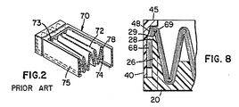
- Crimp sealing and encapsulation of the end pleats 67 is illustrated in Figure 8.
- the compression point 69 of the crimp seal squeezing the filter media occurs between the flanges 45 and the outer edges 29 of the side blades 26.
- inwardly beveled portions 28 of the interior surfaces of the front wall 42a and back wall 44a are aligned with the inwardly beveled portions 28 near the outer edges 29 of the exterior surfaces 26b of the side blades 26.
- the beveled surfaces 28,48 assert additional sealing pressure on the outboard flaps 68 without squeezing the outboard flaps between the encapsulating surfaces 42a, 44a and 26b, this eliminates deformation of the assembled unit 10.
- a cross wall 34 with a plurality of recesses 36 is located midway between the sides 23 of the base 20.
- Figure 7 is a cross-sectional view along the line 7-7 in Figure 3 which shows how the recesses 36 of the cross wall 34 accommodate the pleats 66 of the filter 60 in the assembled unit.
- the cross wall member 34 provides support to the filter media 60. Additionally, the cross wall 34 maintains the spacing between adjacent pleats 66. Maintaining the spacing of the pleats 66 assures that maximum filtering capacity is retained throughout the life of the filter unit 10. It will be appreciated that its cross wall member could be associated with the frame rather than the base and that multiple cross walls may be utilized.
- Figures 1 and 2 illustrate a prior art small disk drive filter assembly 70.
- Current methods of assembly such as adhesives or ultra-sonic welding do not necessarily incapsulate the exposed cut edge of its filter material leaving the filter media prone to chafing and flaking.
- the clear advantages of the crimp seal and encapsulation features of the present invention 10 can be clearly seen when compared to the prior art shown.
- Figure 1 shows how commonly used sealing techniques relying on adhesives can result in adhesive 73 being deposited on and between the pleats of the filter 72 thereby causing a loss of valuable filtering surface.
- outboard end flaps 78 are secured to the housing 75 by an ultra-sonic weld 74 as seen in Figure 7, chafing or flaking of fibers from the filter 72 at the point of the weld 74 can occur.
- encapsulation of the outboard end flaps 68 between the exterior surfaces 26b of the side blades 26 and the interior surfaces 42a and 44a of the front wall 42 and back wall 44 of the frame 40 isolates the outboard flaps 68 from the filtering environment, thereby, minimizing flaking or chafing of media fibers within the disk drive unit.
- Figure 1 further illustrates the potential loss of filtering capacity from distortion of adjacent pleats within the assembly. As discussed previously, this problem is eliminated in the present invention by the uniform pleat spacing established and maintained by the interlocking projections 30, 50 and cross wall 34.
- the base 20 and frame 40 are injection molded from thermo-plastic and can be ultra-sonically welded together.
- the base 20 and frame 40 can be constructed from materials that can be snap locking or adhesively bonded.
- the present invention securely crimp seals and encapsulates a pleated filter in a manner which provides maximum filtering capacity and long term reliability.
- the potential of flaking or chafing of fibers from the exposed cut edges of the filter media which may damage the disk drive unit have been minimized.
- loss of filter capacity from excessive adhesive and distortion of initial pleat spacing have been eliminated.
- the present invention provides a simple and effective solution to the problems which occur with filters presently used in small disk drive units.
Landscapes
- Chemical & Material Sciences (AREA)
- Chemical Kinetics & Catalysis (AREA)
- Filtering Of Dispersed Particles In Gases (AREA)
- Infusion, Injection, And Reservoir Apparatuses (AREA)
- Separation Using Semi-Permeable Membranes (AREA)
- Lubrication Details And Ventilation Of Internal Combustion Engines (AREA)
Abstract
Description
- The present invention relates to a crimp seal pleated filter assembly, particularly for a small disk drive. More particularly, the invention relates to a crimp seal pleated filter assembly as defined in the precharacterising part of claim 1
US-A-2 135 863 and US-A-4 133 661 disclose crimp seal pleated filter media assemblies which comprise a base, a filter medium and a frame. In the filter assembly of US-A-2 135 863 a filtering sheet is clamped and held by wedge acting teeth or ribs that are adapted to be nested between wedge acting ribs on frames one of which is forced into the other. - A similar arrangement is disclosed in US-A-4 133 661 according to which a filtering sheet is forced into a series uniformly spaced plates and is confined between oppositely disposed sets of interdigitated rib segments in a housing comprising two identical housing halves.
- The present invention is intended for use in environments where extremely high degree of filtration is required in a relatively small space. These two requirements tend to conflict and therefore special techniques are required to produce the desired result.
- In the computer field for example, there is a need to provide filtration within the sealed enclosures of hard or "Winchester" disk drives. Hard disk drives have an inflexible platter coated with magnetic material which is spun very rapidly. A magnetic read/write head "flies" only a few microns above the disk on an air cushion. If particulate matter were to become lodged between the disk and the head, the disk drive would be destroyed. On the other hand, there is no space for large and sophisticated filtration equipment within the drive since it is a requirement to make the drives as small as possible.
- An attempt is made to seal the drive units in a clean environment however particulate matter will always exist or be created by matter breaking away from mechanical structures within the drive and therefore filtration is essential. Ordinary filtration however would create more of a problem than a solution since the filter media itself, at it peripheral edges, is a huge source of particulate matter. The fibers in the media itself are much too large to be allowed to float freely within the enclosure. Therefore, it is essential that the filter not only be capable of trapping existing particulate matter but not contribute to that problem by flaking fibers from its edges.
- In the prior art, adhesives have been used to seal the peripheral edges of filter media. This is counter-productive however since the filter assemblies are so small that adhesive seriously reduces the loading capacity of the filter. Remembering that the drive units are sealed for life, there is no opportunity to replace the filter when it is fully loaded.
- A second problem existing in prior art devices is the loss of filter capacity resulting from the inability to maintain spacing between the pleats. Existing filter assemblies do not accommodate the accordion type folds of the filter in a manner that maintains uniform distance between adjacent pleats resulting in distortion and significant filter capacity being lost.
- The present invention overcomes these problems of fiber flaking and improper pleat spacing while maintaining and maximizing the amount of loading capacity of the filter. Furthermore, this goal is accomplished by a simple and inexpensive assembly structure.
- The crimp seal pleated filter assembly of the invention has the characterizing features of claim 1.
- The present invention is particularly adventageous in that no adhesive or ultra-sonic welding is required to seal and encapsulate the filter in the housing. When assembled, the outer ends of the filter are crimp sealed between interlocking projections on the sides of the base and frame. Additionally, side blades along the front and back of the base cooperate with the front wall and back wall of the frame to seal and encapsulate the outboard flaps of the end pleats of the filter.
- Crimp sealing the filter in the present invention results in a number of advantages. First, the available filter area is maximized because adhesives which can accumulate on and between the filter pleats are eliminated. Second, maximum filter capacity is maintained for the life of the filter because the filter housing prevents distortion of the initial pleat alignment.
- Another advantage of the present invention is that flaking or chafing of the fibers from the filter media is reduced. The reduction of flaking or chafing of fibers results from encapsulating the outboard flaps of the end pleats of the filter media between the side blades of the base and the front and back walls of the frame.
- In the preferred embodiment, the base includes a cross wall located midway between the sides of the base. The cross wall includes a plurality of recesses which accommodate individual filter pleats. The recesses of the cross wall are aligned with the interlocking projections of the base and frame and provide support for the filter element within the housing. The cross wall also maintains the separation of the pleats thus enhancing the retention of maximum filter capacity.
- These and various other advantages and features of novelty which characterize the invention are pointed out with particularity in the claims annexed hereto and forming a part hereof. However, for a better understanding of the invention, its advantages, and objects obtained by its use, reference should be had to the drawings which form a further part hereof, and to the accompanying descriptive matter, in which there is illustrated and described a preferred embodiment of the invention.
- In the drawings, in which like reference numerals indicate corresponding parts throughout the several views:
- FIGURE 1 is a perspective view of a prior art filter assembly;
- FIGURE 2 is a cutaway perspective view of a prior art filter assembly;
- FIGURE 3 is a perspective view of a preferred embodiment of the present invention with a partial side break away;
- FIGURE 4 is a bottom perspective view of the preferred embodiment;
- FIGURE 5 is an exploded perspective view of the components of the preferred embodiment of the present invention;
- FIGURE 6 is a cross-sectional view of the present invention along the line 6-6 in Figure 3;
- FIGURE 7 is a cross-sectional view of the present invention along the line 7-7 in Figure 3; and
- FIGURE 8 is an enlarged partial end view with break away side walls.
- Referring now to the drawings, there is shown in Figures 3 - 5 a preferred embodiment of the present invention generally referred to by the reference numeral 10. As is illustrated, the preferred embodiment of the present invention has three components; a generally rectangular
shaped base 20, a generally rectangularshaped frame 40 and afilter element 60. When assembled, thebase 20 andframe 40 crimp seal and encapsulate thefilter media 60. It will be appreciated that although the preferred embodiment includes generally rectangular-shaped components, the components of the assembly could have any generally four-sided shape, including a parallelogram. - The
base 20 of the present invention 10 has a generally rectangular shape and includes a front 22 aback 24 and a pair ofsides 23. Eachside 23 includes a plurality ofprojections 30 with generally pointed outer ends 32 along theinterior surface 23a of theside 23. Theseprojections 30 extend outwardly and perpendicular to thesides 23. In the preferred embodiment, theseprojections 30 have downwardly diverging "V" shapes.Side blades 26 having interior 26a and exterior 26b surfaces are located along the entire length of theinterior surfaces 22a, 22b of the front 22 andback 24 of thebase 20. The exterior surfaces 20b of theside blades 26 have inwardly beveledportions 28 near theouter edges 29 of theblades 26. - The
filter media 60 which is sealed and encapsulated between thebase 20 and theframe 40 includes two sets ofedges pleats 66 which are laterally aligned with one of the sets ofedges 64. The folding of thefilter media 60 results in theends pleats 67 havingoutboard end flaps 68 at each of theedges 64. The other set ofedges 62 form the outer ends of thefilter 60. It will be appreciated that accordion folding thefilter media 60 to create a plurality ofpleats 66 results in maximizing the available filtering surface. - The
frame 40 is generally rectangular in shape and has afront wall 42, aback wall 44 and a pair of side walls 43. Each wall has aninterior surface 42a, 43a and 44a and anexterior surface - In the preferred embodiment, each side wall 43 includes a plurality of
projections 50 having generally pointedouter ends 52 extending outwardly along and adjacent to theinterior surfaces 43a of each side wall 43. In the preferred embodiment, theprojections 50 have upwardly diverging "V" shapes. - An inwardly directed
flange 45 is located adjacent to and perpendicular to the interior surfaces 42a and 44a of thefront wall 42 andback wall 44. Theflange 45 is contiguous with theprojections 50 along the end of theprojections 50 opposite the generally pointed ends 52. - When the invention 10 is assembled, the
frame 40 overlaps thebase 20 and interlockingly cooperates with the base to crimp seal and encapsulate thefilter 60. More specifically, the side walls 43 overlap thesides 23 of thebase 20 and theprojects 50 of the frame interlockingly cooperate with theprojections 30 of thebase 20. Thepleats 66 of thefilter 60 are aligned with theprojections 30 so that the outer ends 62 are crimp sealed between the interlockingprojections interior surfaces 23a of itsbase 20 and theinterior surfaces 43a of the side walls 43. - Figure 6 is a cross-sectional view along line 6-6 in Figure 3 which illustrates the crimp seal and encapsulated outer ends 62 of
filter 60. In Figure 6 the interlocking relationship between theprojections - When the
base 20 andframe 40 are assembled thefront wall 42 and theback wall 44 of theframe 40 overlap theside blades 26 of thebase 20, thereby, crimp sealing the ends pleats 67 and encapsulating theoutboard flaps 68 between theexterior surfaces 26b of theside blades 26 and the interior surfaces 42a, 44a of thefront wall 42 andback wall 44. - In the preferred embodiment 10 the end pleats 67 are crimp sealed between the
outer edges 29 of theside blades 26 and an inwardly directedflange 45 along and adjacent to the interior surfaces 42a and 44a of thefront wall 42, and theback wall 44. Theflange 45 is contiguous with the non-pointed end of theprojections 50 adjacent to and along theinterior surface 43a of the side walls 43. The outboard end flaps 68 are encapsulated between the interior surfaces of the front wall 42a andback wall 42b and theexterior surfaces 26b of theside blades 26. - Crimp sealing and encapsulation of the end pleats 67 is illustrated in Figure 8. In Figure 8 the
compression point 69 of the crimp seal squeezing the filter media occurs between theflanges 45 and theouter edges 29 of theside blades 26. It will be appreciated in the preferred embodiment that inwardly beveledportions 28 of the interior surfaces of the front wall 42a and back wall 44a are aligned with the inwardlybeveled portions 28 near theouter edges 29 of theexterior surfaces 26b of theside blades 26. The beveled surfaces 28,48 assert additional sealing pressure on theoutboard flaps 68 without squeezing the outboard flaps between the encapsulatingsurfaces 42a, 44a and 26b, this eliminates deformation of the assembled unit 10. - In the preferred embodiment, a
cross wall 34 with a plurality ofrecesses 36 is located midway between thesides 23 of thebase 20. Figure 7 is a cross-sectional view along the line 7-7 in Figure 3 which shows how therecesses 36 of thecross wall 34 accommodate thepleats 66 of thefilter 60 in the assembled unit. Thecross wall member 34 provides support to thefilter media 60. Additionally, thecross wall 34 maintains the spacing betweenadjacent pleats 66. Maintaining the spacing of thepleats 66 assures that maximum filtering capacity is retained throughout the life of the filter unit 10. It will be appreciated that its cross wall member could be associated with the frame rather than the base and that multiple cross walls may be utilized. - Figures 1 and 2 illustrate a prior art small disk
drive filter assembly 70. Current methods of assembly such as adhesives or ultra-sonic welding do not necessarily incapsulate the exposed cut edge of its filter material leaving the filter media prone to chafing and flaking. The clear advantages of the crimp seal and encapsulation features of the present invention 10 can be clearly seen when compared to the prior art shown. Figure 1 shows how commonly used sealing techniques relying on adhesives can result in adhesive 73 being deposited on and between the pleats of thefilter 72 thereby causing a loss of valuable filtering surface. - Additionally, when the outboard end flaps 78 are secured to the
housing 75 by anultra-sonic weld 74 as seen in Figure 7, chafing or flaking of fibers from thefilter 72 at the point of theweld 74 can occur. In contrast to this, encapsulation of the outboard end flaps 68 between theexterior surfaces 26b of theside blades 26 and the interior surfaces 42a and 44a of thefront wall 42 andback wall 44 of theframe 40 isolates theoutboard flaps 68 from the filtering environment, thereby, minimizing flaking or chafing of media fibers within the disk drive unit. - Figure 1 further illustrates the potential loss of filtering capacity from distortion of adjacent pleats within the assembly. As discussed previously, this problem is eliminated in the present invention by the uniform pleat spacing established and maintained by the interlocking
projections wall 34. - In the preferred embodiment the
base 20 andframe 40 are injection molded from thermo-plastic and can be ultra-sonically welded together. Alternatively, thebase 20 andframe 40 can be constructed from materials that can be snap locking or adhesively bonded. - The present invention securely crimp seals and encapsulates a pleated filter in a manner which provides maximum filtering capacity and long term reliability. The potential of flaking or chafing of fibers from the exposed cut edges of the filter media which may damage the disk drive unit have been minimized. Also, loss of filter capacity from excessive adhesive and distortion of initial pleat spacing have been eliminated. The present invention provides a simple and effective solution to the problems which occur with filters presently used in small disk drive units.
Claims (6)
- A crimp seal pleated filter assembly, particularly for a disc drive, comprising a four-sided, open housing having first and second opposing portions (20, 40), each portion of said housing having a front (22, 42), back (24, 44), and a pair of sides (23, 43), each front, back, and side having an interior surface facing the interior of the housing, and an exterior surface facing the exterior of the housing, the sides (23, 43) of said housing portions further having projections (30, 50), the projections on each housing portion projecting from the associated housing portion towards the other housing portion, tapering towards the projecting end thereof to interlockingly engage the tapered projections on said other housing; and a pleated filter medium (60) peripherally secured between said housing portions having a plurality of pleats (66), including end pleats (68), and a pair of opposed edges (62) extending transverse to the direction of the pleats, the opposed edges (62) of said filter medium being crimp sealed between the projections (30, 50) on the sides (23, 43) of said housing portions; characterized by the front (22) and back (24) of said first housing portion (20) each having a blade (26) extending along the entire length thereof perpendicularly to the sides of said first housing portion, the front and back of said second housing portion (40) each having inwardly directed flanges (45) extending along the entire length thereof and perpendicularly to the sides of said second housing portion; and the end pleats (68) of said pleated filter medium encapsulated between the blades (26) and the front (42) and back (44) of said other housing portion (40) being crimp sealed between the edges of the blades (26) and the flanges (45).
- A crimp seal pleated filter assembly in accordance with claim 1 wherein the exterior surface of each blade (26) is beveled at the outer edges (29) of the blade, and the interior surfaces of the front and back walls (42, 44) and flanges (45) of said first housing portion (20) are correspondingly beveled (at 48).
- A crimp seal pleated filter assembly in accordance with claim 1 or 2 wherein the housing portions (20, 40) have been injection molded from thermo-plastic.
- A crimp seal pleated filter assembly in accordance with claim 3 wherein the housing portions (20, 40) are ultra-sonically welded together.
- A crimp seal pleated filter assembly in accordance with claim 3 wherein the housing portions (20, 40) are snap-locking.
- A crimp seal pleated filter assembly in accordance with any of claims 1 to 5 wherein said first housing portion (20) includes a cross wall (34) extending between the blades (26) at a point between the side walls (23) of said first housing portion (20), said cross wall having a plurality of recesses (36) formed therein to space apart and support said pleates (66).
Priority Applications (1)
| Application Number | Priority Date | Filing Date | Title |
|---|---|---|---|
| AT85850250T ATE69966T1 (en) | 1984-08-01 | 1985-07-31 | CRIMP SEAL FOR PLEATED FILTER ASSEMBLY. |
Applications Claiming Priority (2)
| Application Number | Priority Date | Filing Date | Title |
|---|---|---|---|
| US636578 | 1984-08-01 | ||
| US06/636,578 US4617122A (en) | 1984-08-01 | 1984-08-01 | Crimp seal pleated filter assembly |
Publications (3)
| Publication Number | Publication Date |
|---|---|
| EP0170643A2 EP0170643A2 (en) | 1986-02-05 |
| EP0170643A3 EP0170643A3 (en) | 1987-09-16 |
| EP0170643B1 true EP0170643B1 (en) | 1991-12-04 |
Family
ID=24552488
Family Applications (1)
| Application Number | Title | Priority Date | Filing Date |
|---|---|---|---|
| EP85850250A Expired - Lifetime EP0170643B1 (en) | 1984-08-01 | 1985-07-31 | Crimp seal pleated filter assembly |
Country Status (6)
| Country | Link |
|---|---|
| US (1) | US4617122A (en) |
| EP (1) | EP0170643B1 (en) |
| JP (1) | JPS61107918A (en) |
| AT (1) | ATE69966T1 (en) |
| CA (1) | CA1259041A (en) |
| DE (1) | DE3584800D1 (en) |
Families Citing this family (148)
| Publication number | Priority date | Publication date | Assignee | Title |
|---|---|---|---|---|
| US4793051A (en) * | 1986-05-13 | 1988-12-27 | Donaldson Company, Inc. | Method for construction of crimp seal pleated filter assembly |
| US4736518A (en) * | 1986-05-13 | 1988-04-12 | Donaldson Company, Inc. | Method and apparatus for construction of crimp seal pleated filter assembly |
| JPS6335416U (en) * | 1986-08-22 | 1988-03-07 | ||
| JPH0520406Y2 (en) * | 1986-09-04 | 1993-05-27 | ||
| SE455378B (en) * | 1986-11-17 | 1988-07-11 | Flodins Filter Ab | PROCEDURE FOR MANUFACTURING FILTERS |
| JPH0414103Y2 (en) * | 1987-12-22 | 1992-03-31 | ||
| JPH0414102Y2 (en) * | 1987-12-22 | 1992-03-31 | ||
| US4953308A (en) * | 1989-02-06 | 1990-09-04 | Vector Corporation | Filter system for a fluid bed granulator/dryer |
| DE3936858A1 (en) * | 1989-11-06 | 1991-05-08 | Thermoplast Technik Ges Fuer K | Corrugated pollen and dust filter sheet adhesively bonded - to rectangular frame with projecting peripheral support tines for corrugations |
| DE4039286C2 (en) * | 1990-12-08 | 2000-11-23 | Mahle Filtersysteme Gmbh | Plate-shaped filter insert for gas filters in particular |
| DE4133175A1 (en) * | 1991-10-07 | 1993-04-08 | Thermoplast Technik Ges Fuer K | METHOD FOR PRODUCING A FILTER CASSETTE, FILTER CASSETTE PRODUCED BY THIS METHOD AND FILTER WITH SUCH A FILTER CASSETTE |
| US20020141910A1 (en) * | 1992-01-07 | 2002-10-03 | Adiletta Joseph G. | Regenerable diesel exhaust filter |
| DE4206738A1 (en) * | 1992-03-04 | 1993-09-09 | Minnesota Mining & Mfg | FILTER ELEMENT FOR FILTERING FLUIDS, IN PARTICULAR FOR FILTERING AIR |
| SE502310C2 (en) * | 1992-11-09 | 1995-10-02 | Mikroklimat Sweden Ab | Air Filter elements |
| US5958236A (en) * | 1993-01-13 | 1999-09-28 | Derrick Manufacturing Corporation | Undulating screen for vibratory screening machine and method of fabrication thereof |
| US6000556A (en) * | 1993-01-13 | 1999-12-14 | Derrick Manufacturing Corporation | Screen assembly for vibratory screening machine |
| EP0680385B1 (en) * | 1993-01-13 | 1999-09-15 | Derrick Manufacturing Corporation | Undulating screen for vibratory screening machine and method of fabrication thereof |
| US5417858A (en) * | 1993-01-13 | 1995-05-23 | Derrick Manufacturing Corporation | Screen assembly for vibrating screening machine |
| US6722504B2 (en) | 1993-04-30 | 2004-04-20 | Varco I/P, Inc. | Vibratory separators and screens |
| US6290068B1 (en) * | 1993-04-30 | 2001-09-18 | Tuboscope I/P, Inc. | Shaker screens and methods of use |
| US6283302B1 (en) | 1993-08-12 | 2001-09-04 | Tuboscope I/P, Inc. | Unibody screen structure |
| USD425531S (en) * | 1999-03-29 | 2000-05-23 | Tuboscope I/P, Inc. | Screen |
| US6371302B1 (en) | 1993-04-30 | 2002-04-16 | Tuboscope I/P, Inc. | Vibratory separator screens |
| US6401934B1 (en) | 1993-04-30 | 2002-06-11 | Tuboscope I/P, Inc. | Ramped screen & vibratory separator system |
| US5598930A (en) * | 1995-07-20 | 1997-02-04 | Advanced Wirecloth, Inc. | Shale shaker screen |
| US5971159A (en) | 1993-04-30 | 1999-10-26 | Tuboscope I/P, Inc. | Screen assembly for a vibratory separator |
| US6454099B1 (en) | 1993-04-30 | 2002-09-24 | Varco I/P, Inc | Vibrator separator screens |
| US6443310B1 (en) | 1993-04-30 | 2002-09-03 | Varco I/P, Inc. | Seal screen structure |
| US6325216B1 (en) | 1993-04-30 | 2001-12-04 | Tuboscope I/P, Inc. | Screen apparatus for vibratory separator |
| US6450345B1 (en) | 1993-04-30 | 2002-09-17 | Varco I/P, Inc. | Glue pattern screens and methods of production |
| US6565698B1 (en) | 1993-04-30 | 2003-05-20 | Varco I/P, Inc. | Method for making vibratory separator screens |
| US6267247B1 (en) | 1993-04-30 | 2001-07-31 | Tuboscope I/P, Inc. | Vibratory separator screen |
| US6152307A (en) | 1993-04-30 | 2000-11-28 | Tuboscope I/P, Inc. | Vibratory separator screens |
| US6269953B1 (en) | 1993-04-30 | 2001-08-07 | Tuboscope I/P, Inc. | Vibratory separator screen assemblies |
| US6607080B2 (en) | 1993-04-30 | 2003-08-19 | Varco I/P, Inc. | Screen assembly for vibratory separators |
| US6629610B1 (en) | 1993-04-30 | 2003-10-07 | Tuboscope I/P, Inc. | Screen with ramps for vibratory separator system |
| US5376270A (en) * | 1993-06-24 | 1994-12-27 | Porous Media Corporation | Box filter |
| US5679122A (en) * | 1993-08-14 | 1997-10-21 | Minnesota Mining & Manufacturing Company | Filter for the filtration of a fluid flow |
| DE4327368A1 (en) * | 1993-08-14 | 1995-02-16 | Minnesota Mining & Mfg | Filters for filtering a fluid flow |
| US5512172A (en) * | 1994-06-10 | 1996-04-30 | Racal Filter Technologies, Ltd. | Method for sealing the edge of a filter medium to a filter assembly and the filter assembly produced thereby |
| DE19524677A1 (en) * | 1994-07-07 | 1996-01-11 | Nippon Denso Co | Air-conditioning filter insert of simple construction having strengthened end-section |
| DE4430333C2 (en) * | 1994-08-29 | 2000-02-17 | Mann & Hummel Filter | filter |
| US5593755A (en) * | 1995-03-07 | 1997-01-14 | Free-Flow Packaging Corporation | Accordion-folded paper sheet packing material and method |
| WO1996035499A1 (en) | 1995-05-12 | 1996-11-14 | Donaldson Company, Inc. | Filter device |
| KR19990023033A (en) * | 1995-06-20 | 1999-03-25 | 노르만 시이 린넬/기에르츠 제임스 알 | How to make filters and filters |
| US5676778A (en) * | 1995-09-05 | 1997-10-14 | The Racal Corporation Canada Inc. | Method of manufacturing a filter assembly and the filter assembly produced thereby |
| US5531892A (en) * | 1995-09-15 | 1996-07-02 | Minnesota Mining And Manufacturing Company | Zigzag filter media and frame having triangular pleat stabilizing elements |
| US5921399A (en) * | 1996-06-07 | 1999-07-13 | Derrick Corporation | Gumbo separator |
| CA2210950A1 (en) * | 1996-07-31 | 1998-01-31 | Richard J. Osendorf | Air filter element; assembly; and method |
| US5743927A (en) * | 1996-07-31 | 1998-04-28 | Donaldson Company, Inc. | Air filter element; assembly; and, method |
| USD405519S (en) | 1996-10-25 | 1999-02-09 | Donaldson Company | Filter element frame member |
| AU132065S (en) | 1996-10-25 | 1997-11-17 | Honeywell Inc | Pleat spacer for air filter |
| US5750021A (en) * | 1996-11-26 | 1998-05-12 | Liang; Chung-Ho | Oil supply and return tube structure for oil tanks in cars and ships |
| DE19704465A1 (en) * | 1997-02-06 | 1998-08-13 | Sartorius Gmbh | Filtration units for fluids with pleated filter element |
| DE19711280A1 (en) * | 1997-03-18 | 1998-09-24 | Freudenberg Carl Fa | Cassette filter with frame |
| US5944197A (en) * | 1997-04-24 | 1999-08-31 | Southwestern Wire Cloth, Inc. | Rectangular opening woven screen mesh for filtering solid particles |
| DE19736290B4 (en) * | 1997-08-21 | 2007-03-29 | Carl Freudenberg Kg | Method for producing a filter arrangement |
| GB9812309D0 (en) * | 1998-06-09 | 1998-08-05 | Smiths Industries Plc | Fluid-treatment devices |
| CA2335772A1 (en) * | 1998-06-26 | 2000-01-06 | Pall Corporation | Internal combustion engine exhaust filters |
| DE19844874A1 (en) * | 1998-09-30 | 2000-04-06 | Knecht Filterwerke Gmbh | Plate filter element for an air filter |
| US6932883B2 (en) | 1998-10-30 | 2005-08-23 | Varco I/P, Inc. | Screens for vibratory separators |
| US6736270B2 (en) | 1998-10-30 | 2004-05-18 | Varco I/P, Inc. | Glued screens for shale shakers |
| US6669985B2 (en) | 1998-10-30 | 2003-12-30 | Varco I/P, Inc. | Methods for making glued shale shaker screens |
| US6245130B1 (en) | 1999-06-29 | 2001-06-12 | Philip D. Maybee | Filter system |
| US8449638B2 (en) | 1999-11-05 | 2013-05-28 | Donaldson Company, Inc. | Filter element, air cleaner, and methods |
| US6348084B1 (en) | 1999-11-05 | 2002-02-19 | Donaldson Company, Inc. | Filter element, air cleaner, and methods |
| US20040007508A1 (en) | 1999-12-04 | 2004-01-15 | Schulte David L. | Screen assembly for vibratory separator |
| DE20113026U1 (en) * | 2000-08-18 | 2002-01-31 | Helsa-Werke Helmut Sandler GmbH & Co. KG, 95482 Gefrees | Filter device with a predetermined flow direction |
| US6610126B2 (en) | 2001-06-06 | 2003-08-26 | Donaldson Company, Inc. | Filter element having sealing members and methods |
| DE10131422C2 (en) * | 2001-06-29 | 2003-05-08 | Sandler Helmut Helsa Werke | Filter element with a pleated filter pack |
| DE10138880B4 (en) * | 2001-07-13 | 2004-09-02 | Helsa-Werke Helmut Sandler Gmbh & Co. Kg | Flexible filter |
| US6740136B2 (en) * | 2001-10-12 | 2004-05-25 | 3M Innovative Properties Company | Interconnected filter frame and filter framing method |
| US6874458B2 (en) | 2001-12-28 | 2005-04-05 | Kohler Co. | Balance system for single cylinder engine |
| US6966940B2 (en) | 2002-04-04 | 2005-11-22 | Donaldson Company, Inc. | Air filter cartridge |
| KR100956706B1 (en) | 2002-05-09 | 2010-05-06 | 도날드슨 컴파니, 인코포레이티드 | Air filter with pull root filter media |
| US6860916B2 (en) * | 2002-06-14 | 2005-03-01 | 3M Innovative Properties Company | Filter assembly |
| US6740137B2 (en) * | 2002-06-14 | 2004-05-25 | 3M Innovative Properties Company | Collapsible pleated filter element |
| US6955702B2 (en) * | 2002-06-14 | 2005-10-18 | 3M Innovative Properties Company | Filter frame |
| US6739304B2 (en) | 2002-06-28 | 2004-05-25 | Kohler Co. | Cross-flow cylinder head |
| US6732701B2 (en) | 2002-07-01 | 2004-05-11 | Kohler Co. | Oil circuit for twin cam internal combustion engine |
| US6684846B1 (en) | 2002-07-18 | 2004-02-03 | Kohler Co. | Crankshaft oil circuit |
| US6837206B2 (en) | 2002-07-11 | 2005-01-04 | Kohler Co. | Crankcase cover with oil passages |
| USD474266S1 (en) | 2002-07-18 | 2003-05-06 | Kohler Co. | Air filter |
| US6978751B2 (en) | 2002-07-18 | 2005-12-27 | Kohler Co. | Cam follower arm for an internal combustion engine |
| US6742488B2 (en) | 2002-07-18 | 2004-06-01 | Kohler Co. | Component for governing air flow in and around cylinder head port |
| US6837207B2 (en) | 2002-07-18 | 2005-01-04 | Kohler Co. | Inverted crankcase with attachments for an internal combustion engine |
| US6752846B2 (en) | 2002-07-18 | 2004-06-22 | Kohler Co. | Panel type air filter element with integral baffle |
| DE10235122B3 (en) * | 2002-08-01 | 2004-01-08 | Helsa-Werke Helmut Sandler Gmbh & Co. Kg | Flexible filter |
| US6986799B2 (en) * | 2002-08-21 | 2006-01-17 | Romanow Enterprises, Inc. | Recyclable air filter |
| JP3809865B2 (en) * | 2002-12-26 | 2006-08-16 | ヤマトヨ産業株式会社 | Air cleaning filter device |
| CA2519812C (en) * | 2003-03-24 | 2009-01-13 | Jms Co., Ltd. | Blood filter device and method of producing the same |
| US7004989B2 (en) * | 2003-08-22 | 2006-02-28 | Camfil Farr, Inc. | Filter assembly with compressed media edge seal |
| US7591868B2 (en) * | 2003-10-07 | 2009-09-22 | Donaldson Company, Inc. | Filter for electronic enclosure |
| CN1890013B (en) | 2003-11-12 | 2010-10-27 | 唐纳森公司 | Air filter with a sliding frame for a filter element |
| US7070641B1 (en) | 2003-12-03 | 2006-07-04 | Fleetguard, Inc. | Carbon media filter element |
| US7169202B2 (en) * | 2003-12-24 | 2007-01-30 | 3M Innovative Properties Company | Filter assembly |
| US7166142B2 (en) * | 2003-12-31 | 2007-01-23 | Donaldson Company, Inc. | Filter constructions containing breather and recirculation filter elements |
| US7125433B2 (en) | 2003-12-31 | 2006-10-24 | Donaldson Company, Inc. | Dual diffusion channel filter |
| EP2679293A1 (en) | 2004-03-24 | 2014-01-01 | Donaldson Company, Inc. | Air Cleaner |
| US7258789B2 (en) | 2004-04-20 | 2007-08-21 | Spx Corporation | Non-planar media transmission filter apparatus and method with tray |
| US7261814B2 (en) * | 2004-04-20 | 2007-08-28 | Spx Corporation | Non-planar media transmission filter apparatus and method |
| US7905936B2 (en) | 2004-04-30 | 2011-03-15 | Donaldson Company, Inc. | Filter arrangements; housing; assemblies; and, methods |
| BRPI0510467B8 (en) | 2004-04-30 | 2016-10-11 | Donaldson Co Inc | Air filter cartridge arrangement removably installed in an air cleaning housing during use and air filter assembly. |
| US8048188B2 (en) | 2004-06-18 | 2011-11-01 | Donaldson Company, Inc. | Air cleaner arrangements; serviceable filter cartridge; and, methods |
| US7252696B2 (en) * | 2004-09-02 | 2007-08-07 | Carrier Corporation | Fan coil media cabinet |
| US7247183B2 (en) * | 2004-09-29 | 2007-07-24 | Fleetguard, Inc. | Panel filter with gasket seal |
| US7828870B1 (en) | 2004-11-24 | 2010-11-09 | Cummins Filtration Ip, Inc. | Filter assembly with cost effective seal |
| US7413588B2 (en) * | 2004-11-24 | 2008-08-19 | Fleetguard, Inc. | High efficiency, low restriction, cost effective filter |
| JP2006205133A (en) * | 2005-01-31 | 2006-08-10 | Toyo Roki Mfg Co Ltd | Filter element |
| WO2006093960A2 (en) * | 2005-02-28 | 2006-09-08 | Donaldson Company, Inc. | Filter arrangement and methods |
| US20060272507A1 (en) * | 2005-04-04 | 2006-12-07 | Johnson Christopher M | Adsorbent Carbon Breather with Scrim for Improved Flow |
| US20070056444A1 (en) * | 2005-07-12 | 2007-03-15 | Garikipati Vijay K | Electronic Enclosure Filter Containing Fluted Media |
| US20070103811A1 (en) * | 2005-09-09 | 2007-05-10 | Olszewski Jason R | Filtration arrangment for electronic enclosure |
| EP2051791B1 (en) | 2006-08-14 | 2014-10-08 | Evoqua Water Technologies LLC | High flow disc filter |
| DE102006043729A1 (en) * | 2006-09-13 | 2008-03-27 | Mann + Hummel Gmbh | Filter or adsorber element with enclosed adsorption particles and a process for its preparation |
| US7785384B2 (en) | 2007-01-09 | 2010-08-31 | Honeywell International Inc. | Pleated diesel particulate filter assembly |
| CN101743051B (en) | 2007-07-13 | 2015-09-09 | 唐纳森公司 | Contamination Control Filters with Fill Port |
| US8118175B2 (en) | 2007-07-18 | 2012-02-21 | Siemens Industry, Inc. | Venting device for a disc filter |
| US8801929B2 (en) | 2007-07-18 | 2014-08-12 | Evoqua Water Technologies Llc | Trash tolerant filter support for a disc filter |
| US8061530B2 (en) | 2009-04-09 | 2011-11-22 | Cummins Filtration Ip, Inc. | Filtration sealing system |
| WO2010130698A1 (en) * | 2009-05-14 | 2010-11-18 | Mann+Hummel Gmbh | Method for producing an in particular rectangular flat filter element for fluids, filter element, and filter device having a filter element |
| US8197571B2 (en) * | 2009-05-29 | 2012-06-12 | Aaf-Mcquay Inc. | Air filter with improved structural support |
| CN102264452B (en) | 2009-10-02 | 2016-02-24 | 唐纳森公司 | There is the filter element of central plate, dust arrester and method |
| DE102009056759A1 (en) * | 2009-12-04 | 2011-06-09 | Carl Freudenberg Kg | Filter arrangement with overlapping swords |
| DE102010023973A1 (en) * | 2010-06-16 | 2011-12-15 | Mahle International Gmbh | filter cartridge |
| KR101262789B1 (en) * | 2011-07-06 | 2013-05-09 | (주) 골프존 | Penetration type screen for screen golf |
| WO2014111162A1 (en) * | 2013-01-18 | 2014-07-24 | Tripleair Technology B.V. | Housing for a pleated filter and method for manufacturing thereof |
| JP2015016435A (en) * | 2013-07-11 | 2015-01-29 | キヤノン株式会社 | Filter assembly |
| KR101564759B1 (en) * | 2014-02-04 | 2015-11-02 | 한국과학기술연구원 | Separation Membrame for Membrane Distillation |
| KR101524225B1 (en) * | 2014-02-04 | 2015-05-29 | 한국과학기술연구원 | Membrane Distillation Module |
| EP3151943B8 (en) | 2014-06-05 | 2021-03-31 | Evoqua Water Technologies LLC | Filtering panel and method of making the same |
| CN108367214B (en) | 2015-12-11 | 2021-04-16 | 康明斯过滤Ip公司 | Filter with variable cross section axial seal |
| CN114288725B (en) | 2016-03-18 | 2023-06-13 | 康明斯过滤Ip公司 | Interlocking stable filter assembly |
| US11141687B2 (en) | 2016-05-02 | 2021-10-12 | Cummins Filtration Ip, Inc. | Filter with interlocking housing interface |
| EA037761B1 (en) | 2016-08-12 | 2021-05-19 | Эвокуа Уотер Текнолоджиз Ллк | Disc filter pre-screen dual media disc filter |
| DE112018000527T5 (en) | 2017-01-25 | 2019-10-10 | Cummins Filtration Ip, Inc. | ADVANCED THREADED ADAPTER FOR THREADLESS COAT |
| US11724220B2 (en) | 2017-02-21 | 2023-08-15 | Cummins Filtration Ip, Inc. | Undulated interlocking housing-endplate interface geometry |
| US11235275B2 (en) | 2017-03-16 | 2022-02-01 | Cummins Filtration Ip, Inc. | Filtration sealing system |
| WO2018191147A1 (en) | 2017-04-11 | 2018-10-18 | Cummins Filtration Ip, Inc. | Panel filter element |
| US10569201B2 (en) | 2017-06-15 | 2020-02-25 | Jordacon Enterprises Llc | Filter device and method |
| USD914187S1 (en) | 2017-10-06 | 2021-03-23 | Kohler Co. | Air cleaner filter |
| AR113747A1 (en) * | 2017-10-06 | 2020-06-10 | Candu Energy Inc | METHOD AND APPARATUS FOR FILTERING FLUIDS IN NUCLEAR ENERGY GENERATION |
| WO2020021418A1 (en) | 2018-07-23 | 2020-01-30 | Cummins Filtration Sarl | Radial seal for spin-on filter |
| US11745132B2 (en) | 2019-11-20 | 2023-09-05 | PaintMaxx LLC | Filter and filter assembly for paint overspray capture |
| CN115103714A (en) | 2020-02-11 | 2022-09-23 | 康明斯滤清系统公司 | Advanced fuel filtration system with interlocking cartridge seal design |
| US11745131B2 (en) * | 2020-06-29 | 2023-09-05 | Omachron Intellectual Property Inc. | Filter assembly |
| US11992796B2 (en) * | 2020-07-09 | 2024-05-28 | Baldwin Filters, Inc. | Filter frame with foldable sealing flap |
| US20230191306A1 (en) * | 2021-12-22 | 2023-06-22 | Sdi Diagnostics, Inc. | Breathing tube filter and filter assembly |
Family Cites Families (24)
| Publication number | Priority date | Publication date | Assignee | Title |
|---|---|---|---|---|
| US1104159A (en) * | 1913-05-26 | 1914-07-21 | William S Witter | Spark-plug. |
| US1171952A (en) * | 1915-07-09 | 1916-02-15 | Higgin Mfg Co | Knockdown window-screen. |
| US1832281A (en) * | 1929-08-15 | 1931-11-17 | Davies Charles | Ventilator |
| US2058669A (en) * | 1932-10-26 | 1936-10-27 | Staynew Filter Corp | Air filter |
| US1987860A (en) * | 1934-02-08 | 1935-01-15 | Orange Screen Company | Window screen |
| US2130107A (en) * | 1936-02-06 | 1938-09-13 | Herbert J Somers | Filter |
| US2071806A (en) * | 1936-04-06 | 1937-02-23 | Universal Air Filter Corp | Air filter for ventilating systems or apparatus |
| US2135863A (en) * | 1937-07-09 | 1938-11-08 | Warren S Moore | Air filter |
| US2709489A (en) * | 1953-03-16 | 1955-05-31 | B & G Mfg Company | Window screens |
| US3142550A (en) * | 1962-06-01 | 1964-07-28 | Fibercraft Products Inc | Plastic filter frame |
| US3695012A (en) * | 1970-04-23 | 1972-10-03 | Donaldson Co Inc | Filter assembly with pleated filter element |
| DE2020246A1 (en) * | 1970-04-25 | 1971-11-11 | Jrb Ingenieurgesellschaft Rein | Gas filter |
| US3712033A (en) * | 1971-06-01 | 1973-01-23 | Donaldson Co Inc | Air cleaner with hinged side walls |
| DE2135813B2 (en) * | 1971-07-17 | 1975-07-10 | Draegerwerk Ag, 2400 Luebeck | HEPA filter insert for breathing apparatus made from a folded filter sheet |
| BE788210A (en) * | 1971-09-16 | 1973-02-28 | Pall Corp | FILTER BOX |
| IT977658B (en) * | 1972-02-03 | 1974-09-20 | Knecht Filterwerke Gmbh | DISC-SHAPED FILTER CARTRIDGE FOR COMBUSTION ENGINES |
| US3793813A (en) * | 1972-05-19 | 1974-02-26 | American Air Filter Co | Pleated filter assembly |
| DE2327605A1 (en) * | 1973-05-30 | 1975-01-02 | A W Schirp Kg | FILTER CELL FRAME |
| US4165287A (en) * | 1977-04-04 | 1979-08-21 | Cobe Laboratories, Inc. | Potting pleated membrane |
| US4133661A (en) * | 1977-11-25 | 1979-01-09 | General Motors Corporation | Air filter assembly |
| US4187182A (en) * | 1978-07-21 | 1980-02-05 | Pall Corporation | Box filter |
| JPS5662113U (en) * | 1979-10-17 | 1981-05-26 | ||
| US4386948A (en) * | 1979-12-20 | 1983-06-07 | American Hospital Supply Corporation | Filter drive |
| JPS5835302U (en) * | 1981-09-02 | 1983-03-08 | 株式会社吉野工業所 | compact container |
-
1984
- 1984-08-01 US US06/636,578 patent/US4617122A/en not_active Expired - Lifetime
-
1985
- 1985-07-31 DE DE8585850250T patent/DE3584800D1/en not_active Expired - Fee Related
- 1985-07-31 CA CA000487831A patent/CA1259041A/en not_active Expired
- 1985-07-31 AT AT85850250T patent/ATE69966T1/en not_active IP Right Cessation
- 1985-07-31 EP EP85850250A patent/EP0170643B1/en not_active Expired - Lifetime
- 1985-08-01 JP JP60168654A patent/JPS61107918A/en active Granted
Also Published As
| Publication number | Publication date |
|---|---|
| US4617122A (en) | 1986-10-14 |
| ATE69966T1 (en) | 1991-12-15 |
| EP0170643A2 (en) | 1986-02-05 |
| JPH0350569B2 (en) | 1991-08-02 |
| CA1259041A (en) | 1989-09-05 |
| EP0170643A3 (en) | 1987-09-16 |
| DE3584800D1 (en) | 1992-01-16 |
| JPS61107918A (en) | 1986-05-26 |
Similar Documents
| Publication | Publication Date | Title |
|---|---|---|
| US4617122A (en) | Crimp seal pleated filter assembly | |
| US6740136B2 (en) | Interconnected filter frame and filter framing method | |
| CA1308366C (en) | Hepa air filter for high temperature environments and method of fabrication | |
| US4728426A (en) | Filter pack | |
| EP1214963A2 (en) | Multi-panel filter | |
| CA1074712A (en) | Self cleaning fluid sealed air filter | |
| US4547950A (en) | Method of spacing the folds of a folded filter media | |
| EP2237850B1 (en) | High flow v-bank filter | |
| CA2097274C (en) | Extended surface pocket type air filter | |
| EP1166843A1 (en) | Fluid filter | |
| KR960006980A (en) | filter | |
| CA2301452A1 (en) | Pleated filter media with strip spacers and method of making | |
| CN111135651A (en) | Filter element, cassette filter and filter insert having a reverse fold arrangement | |
| EP0250801A1 (en) | Convoluted panel filter cartridge | |
| JPH0779937B2 (en) | Air filters and modules for air filters | |
| DE69020591T2 (en) | Magnetic disk unit. | |
| US3222850A (en) | Filter | |
| US5995323A (en) | Circulation filter mounting structure in disk drive | |
| JPH0470921B2 (en) | ||
| CA1081138A (en) | Assymetrical mechanical filter | |
| US4795481A (en) | Air filter with high dust-holding capacity | |
| GB2375494A (en) | Filter assembly | |
| JP2790857B2 (en) | Filter for air purifier | |
| GB2294468A (en) | Electrically conductive composite polymeric material | |
| SU1736560A1 (en) | Edge filter |
Legal Events
| Date | Code | Title | Description |
|---|---|---|---|
| PUAI | Public reference made under article 153(3) epc to a published international application that has entered the european phase |
Free format text: ORIGINAL CODE: 0009012 |
|
| AK | Designated contracting states |
Designated state(s): AT BE CH DE FR GB IT LI LU NL SE |
|
| PUAL | Search report despatched |
Free format text: ORIGINAL CODE: 0009013 |
|
| AK | Designated contracting states |
Kind code of ref document: A3 Designated state(s): AT BE CH DE FR GB IT LI LU NL SE |
|
| 17P | Request for examination filed |
Effective date: 19871107 |
|
| 17Q | First examination report despatched |
Effective date: 19880318 |
|
| GRAA | (expected) grant |
Free format text: ORIGINAL CODE: 0009210 |
|
| AK | Designated contracting states |
Kind code of ref document: B1 Designated state(s): AT BE CH DE FR GB IT LI LU NL SE |
|
| PG25 | Lapsed in a contracting state [announced via postgrant information from national office to epo] |
Ref country code: SE Effective date: 19911204 Ref country code: NL Effective date: 19911204 Ref country code: LI Effective date: 19911204 Ref country code: CH Effective date: 19911204 Ref country code: BE Effective date: 19911204 Ref country code: AT Effective date: 19911204 |
|
| REF | Corresponds to: |
Ref document number: 69966 Country of ref document: AT Date of ref document: 19911215 Kind code of ref document: T |
|
| ITF | It: translation for a ep patent filed | ||
| ET | Fr: translation filed | ||
| REF | Corresponds to: |
Ref document number: 3584800 Country of ref document: DE Date of ref document: 19920116 |
|
| REG | Reference to a national code |
Ref country code: CH Ref legal event code: PL |
|
| NLV1 | Nl: lapsed or annulled due to failure to fulfill the requirements of art. 29p and 29m of the patents act | ||
| PG25 | Lapsed in a contracting state [announced via postgrant information from national office to epo] |
Ref country code: LU Free format text: LAPSE BECAUSE OF NON-PAYMENT OF DUE FEES Effective date: 19920731 |
|
| PLBE | No opposition filed within time limit |
Free format text: ORIGINAL CODE: 0009261 |
|
| STAA | Information on the status of an ep patent application or granted ep patent |
Free format text: STATUS: NO OPPOSITION FILED WITHIN TIME LIMIT |
|
| 26N | No opposition filed | ||
| PGFP | Annual fee paid to national office [announced via postgrant information from national office to epo] |
Ref country code: FR Payment date: 19980618 Year of fee payment: 14 |
|
| PG25 | Lapsed in a contracting state [announced via postgrant information from national office to epo] |
Ref country code: FR Free format text: THE PATENT HAS BEEN ANNULLED BY A DECISION OF A NATIONAL AUTHORITY Effective date: 19990731 |
|
| REG | Reference to a national code |
Ref country code: FR Ref legal event code: ST |
|
| PGFP | Annual fee paid to national office [announced via postgrant information from national office to epo] |
Ref country code: GB Payment date: 20001228 Year of fee payment: 16 |
|
| PGFP | Annual fee paid to national office [announced via postgrant information from national office to epo] |
Ref country code: DE Payment date: 20001229 Year of fee payment: 16 |
|
| PG25 | Lapsed in a contracting state [announced via postgrant information from national office to epo] |
Ref country code: GB Free format text: LAPSE BECAUSE OF NON-PAYMENT OF DUE FEES Effective date: 20010731 |
|
| GBPC | Gb: european patent ceased through non-payment of renewal fee |
Effective date: 20010731 |
|
| PG25 | Lapsed in a contracting state [announced via postgrant information from national office to epo] |
Ref country code: DE Free format text: LAPSE BECAUSE OF NON-PAYMENT OF DUE FEES Effective date: 20020501 |