EP0170403A1 - Anti-friction and non-oscillating spool for belt driven cartridge - Google Patents
Anti-friction and non-oscillating spool for belt driven cartridge Download PDFInfo
- Publication number
- EP0170403A1 EP0170403A1 EP85304569A EP85304569A EP0170403A1 EP 0170403 A1 EP0170403 A1 EP 0170403A1 EP 85304569 A EP85304569 A EP 85304569A EP 85304569 A EP85304569 A EP 85304569A EP 0170403 A1 EP0170403 A1 EP 0170403A1
- Authority
- EP
- European Patent Office
- Prior art keywords
- pin
- spool
- tape
- flanges
- tape spool
- Prior art date
- Legal status (The legal status is an assumption and is not a legal conclusion. Google has not performed a legal analysis and makes no representation as to the accuracy of the status listed.)
- Granted
Links
- 238000004804 winding Methods 0.000 claims abstract description 8
- 239000000463 material Substances 0.000 claims description 9
- DHKHKXVYLBGOIT-UHFFFAOYSA-N 1,1-Diethoxyethane Chemical compound CCOC(C)OCC DHKHKXVYLBGOIT-UHFFFAOYSA-N 0.000 claims description 4
- 238000005299 abrasion Methods 0.000 claims description 4
- 239000011354 acetal resin Substances 0.000 claims description 4
- 239000002184 metal Substances 0.000 claims description 4
- 229910052751 metal Inorganic materials 0.000 claims description 4
- 239000004417 polycarbonate Substances 0.000 claims description 4
- 229920000515 polycarbonate Polymers 0.000 claims description 4
- 229920006324 polyoxymethylene Polymers 0.000 claims description 4
- 229920000642 polymer Polymers 0.000 claims description 2
- 230000010355 oscillation Effects 0.000 abstract description 4
- 239000000853 adhesive Substances 0.000 description 2
- 230000001070 adhesive effect Effects 0.000 description 2
- 230000004907 flux Effects 0.000 description 2
- 230000005484 gravity Effects 0.000 description 2
- 238000012986 modification Methods 0.000 description 2
- 230000004048 modification Effects 0.000 description 2
- 239000004033 plastic Substances 0.000 description 2
- 229920003023 plastic Polymers 0.000 description 2
- 230000002441 reversible effect Effects 0.000 description 2
- 238000003466 welding Methods 0.000 description 2
- 230000001133 acceleration Effects 0.000 description 1
- XECAHXYUAAWDEL-UHFFFAOYSA-N acrylonitrile butadiene styrene Chemical compound C=CC=C.C=CC#N.C=CC1=CC=CC=C1 XECAHXYUAAWDEL-UHFFFAOYSA-N 0.000 description 1
- 229920000122 acrylonitrile butadiene styrene Polymers 0.000 description 1
- 239000004676 acrylonitrile butadiene styrene Substances 0.000 description 1
- 229910052782 aluminium Inorganic materials 0.000 description 1
- XAGFODPZIPBFFR-UHFFFAOYSA-N aluminium Chemical compound [Al] XAGFODPZIPBFFR-UHFFFAOYSA-N 0.000 description 1
- 230000008878 coupling Effects 0.000 description 1
- 238000010168 coupling process Methods 0.000 description 1
- 238000005859 coupling reaction Methods 0.000 description 1
- 230000000254 damaging effect Effects 0.000 description 1
- 230000001627 detrimental effect Effects 0.000 description 1
- 238000010438 heat treatment Methods 0.000 description 1
- 229920005669 high impact polystyrene Polymers 0.000 description 1
- 239000004797 high-impact polystyrene Substances 0.000 description 1
- 238000003780 insertion Methods 0.000 description 1
- 230000037431 insertion Effects 0.000 description 1
- 238000004519 manufacturing process Methods 0.000 description 1
- 238000000034 method Methods 0.000 description 1
Images
Classifications
-
- G—PHYSICS
- G11—INFORMATION STORAGE
- G11B—INFORMATION STORAGE BASED ON RELATIVE MOVEMENT BETWEEN RECORD CARRIER AND TRANSDUCER
- G11B23/00—Record carriers not specific to the method of recording or reproducing; Accessories, e.g. containers, specially adapted for co-operation with the recording or reproducing apparatus ; Intermediate mediums; Apparatus or processes specially adapted for their manufacture
- G11B23/02—Containers; Storing means both adapted to cooperate with the recording or reproducing means
- G11B23/04—Magazines; Cassettes for webs or filaments
- G11B23/08—Magazines; Cassettes for webs or filaments for housing webs or filaments having two distinct ends
- G11B23/087—Magazines; Cassettes for webs or filaments for housing webs or filaments having two distinct ends using two different reels or cores
- G11B23/08707—Details
- G11B23/08728—Reels or cores; positioning of the reels in the cassette
-
- G—PHYSICS
- G11—INFORMATION STORAGE
- G11B—INFORMATION STORAGE BASED ON RELATIVE MOVEMENT BETWEEN RECORD CARRIER AND TRANSDUCER
- G11B23/00—Record carriers not specific to the method of recording or reproducing; Accessories, e.g. containers, specially adapted for co-operation with the recording or reproducing apparatus ; Intermediate mediums; Apparatus or processes specially adapted for their manufacture
- G11B23/02—Containers; Storing means both adapted to cooperate with the recording or reproducing means
- G11B23/037—Single reels or spools
Definitions
- the present invention concerns an improved tape spool for a two-spool tape cartridge in which a flexible, elastic drive belt contacts the tape on the tape spools and whereby movement of the belt causes movement of the tape between the spools.
- the belt driven tape cartridge of U.S. patent no. 3,692,255, issued to Von Behren and assigned to the assignee of the present invention has been very successfully utilized to interface with computers where rapid acceleration and deceleration of the tape are required.
- a magnetic recording tape is convolutely wound on two tape spools and is bidirectionally driven between the spools by an endless flexible belt in frictional contact with the tape on both spools.
- the present invention discloses a tape spool for use in a data cartridge which includes an anti-friction bearing and means for retaining the spool at a predetermined axial position with respect to the cartridge.
- the tape spool is adapted for mounting on and rotation around a cylindrical pin extending a predetermined distance from one of the cartridge walls, and includes two flanges interconnected by a hub providing a cylindrical tape winding surface, a bore extending through the hub and one of the flanges and closely but freely fitting the pin, a bearing protrusion, which may be hemispherical, extending from the other of the flanges into the bore, wherein the extension of the pin from the cartridge wall is greater than the length of the hub bore to the bearing protrusion so that the spool is suspended above the cartridge wall for free rotation about the pin. Frictional contact between the cartridge and the spool is limited to the hemispherical protrusion of the flange and the end of the pin, and thus is very low.
- the improved tape spool of the invention may also include a wear-button protrusion extending from the other of the flanges opposite and coaxial with the hub bore which may be contacted by a spring connected to an inner wall of the cartridge, which spring resiliently biases the spool into contact with the pin and resists axial movement of the spool.
- a wear-button protrusion extending from the other of the flanges opposite and coaxial with the hub bore which may be contacted by a spring connected to an inner wall of the cartridge, which spring resiliently biases the spool into contact with the pin and resists axial movement of the spool.
- FIGURES 1 and 2 illustrate a data cartridge 10 of the type described in U.S. patent no. 3,692,255 (Von B ehren) which includes a thin base plate 12, usually of aluminum, and a clear or translucent polymeric cover 14, which, when assembled, define a thin, generally rectangular enclosure.
- the tape spools 16 and 18 are supported by the cartridge base plate 12 for free rotation about spaced parallel axes.
- the magnetic recording tape 30 is convolutely wound on the tape spools 16 and 18 in opposite directions about their axes.
- a tape 30 guide path between the tape spools 16 and 18 is defined by the three tape wrap pins 20, 22 and 24 and the two tape guides 26 and 28.
- the cartridge 10 is formed with a cutaway portion 40 along the tape path which provides access to the magnetic tape 30 by a magnetic transducer 42.
- the cutaway portion 40 is normally closed by a spring-loaded door 44 which is opened as shown upon insertion of the data cartridge 10 into a tape recorder (not shown).
- second opening 46 is provided in the cartridge cover 14 to provide access to the belt driving roller 38 by a drive roller 48 driven by a reversible motor 50.
- the magnetic transducer 42, the drive roller 48, and the reversible motor 50 are illustrated in phantom lines as they form a portion of the tape recorder rather than the data cartridge 10.
- the cartridge belt driving roller 38 is provided with a reduced diameter 51 to prevent contact between the driving belt 32 and the magnetic recording tape 30.
- the driving belt 32 is thin, continuous, flexible and elastic. It has a uniform cross-sectional area and it extends around the belt driving roller 38 and the belt guide rollers 34 and 36, contacting the tape 30 on the tape spools 16 and 18.
- the length of the belt 32 is less than the length of the path along which it extends so that when the belt 32 is stretched into position it will have an installed tension or pretension.
- the angle of wrap of the driving belt 32 at the tape spools 16 and 18 is at least 60 degrees and provides the necessary contact between the belt 32 and the tape 30 wound on the tape spools 16 and 18 to assure frictional driving of the tape 30 and the tape spools 16 and 18.
- Rotation of the belt driving roller 38 in a counterclockwise direction (as viewed in FIGURE 1) by the drive roller 48 causes the belt 32 to traverse its path in a counterclockwise direction and the tape 30 to move from the tape spool 18 to the tape spool 16, the tape spool 18 serving as a supply spool and the tape spool 16 serving as a take-up spool.
- Opposite rotation of the driving roller 38 by the drive roller 48 will cause tape to be supplied by the tape spool 16 and convolutely wound upon the tape spool 18.
- a predetermined frictional coupling between the belt guide rollers 34 and 36 and their respective support shafts applies a predetermined drag to the belt 32 as it passes around the guide belt rollers 34 and 36, thereby increasing the tension of the belt 32 as it passes around each of the guide rollers 34 and 36.
- This increased tension Oil the bert 32 increases the length of the belt 32 according to its elasticity and thereby the speed at which the belt 32 passes around the spool 18 is increased compared to that at which it passes around the spool 16.
- This increased speed causes tension in the tape 30 as well as the ability to take up any slack developed in the tape 30 between the tape spools 16 and 18 as is more fully taught in U.S. patent no. 3,692,255.
- the improved tape spool 16 or 18 of the present invention is best illustrated in FIGURE 2 and includes an upper flange 52 and a lower flange 54 interconnected by a hub 56 providing a cylindrical tape winding surface 58.
- the spool 16 or 18 is preferably molded of plastic with the hub 56 and lower flange 54 molded as a single unit and the upper flange 52 molded separately and attached to the hub 56 either by an adhesive or welding.
- the spool 16 or 18 is mounted to the cartridge 10 on and for rotation around a pin 60 which is press-fitted into a hole 62 in the cartridge plate 12 to extend a predetermined distance above the plate 12.
- the spool 16 or 18 is journaled for free rotation around the pin 60 by means of a bore 64 provided in the hub 56, which bore is sized to closely but freely fit the diameter of the pin 60.
- the upper flange 52 is provided with a bearing protuberance 66 which extends into the hub bore 64 and contacts the pin 60.
- the bearing protuberance 66 is preferably frusto-conical or hemispherical in shape and preferably has a rounded surface 68 which reduces the area of contact between the protuberance 66 and the pin 60. It will be recognized, however, that the protuberance 66 could simply be a cylindrical projection which contacts the pin 60 at a flat surface or the pin 60 could simply contact the flange 52.
- the protuberance 66 it is desirable, however, to include the bulk of material provided by the protuberance 66, rather than simply allowing the pin 60 to contact the flat, lower surface of the upper flange 52, because the upper flange 52 is molded of a polymer and may be somewhat abraded or frictionally heated by contact with the pin 60.
- the relatively large bulk of material provided by the protuberance 66 minimizes any damaging effects caused by such heating and the rounded shape of its surface 68 further minimizes heat caused by friction and reduces abrasion caused by the pin 60.
- the terminal surface 70 of the pin 60 may likewise be rounded rather than flat as illustrated.
- the length of the pin 60, from the surface of the cartridge plate 12 to its terminal end 70, is selected to be slightly greater than the length of the hub bore 64 from the flange 54 to the protuberance 66 so that the spool 16 or 18 is suspended by contact between the pin 60 and the protuberance 66 such that the lower flange 54 rotates free of contact with the cartridge plate 12.
- the data cartridge 10 may be oriented in use in a position other than that shown in FIGURE 2, in which case gravity would not assist in maintaining the protuberance 66 in contact with the pin 60.
- the upper flange 52 is further provided with a wear-button protuberance 72 extending from the flange 52 opposite and coaxial with the hub bore 64.
- the cartridge cover 14 is provided with a spring 74 which contacts the wear-button protuberance 74 and urges the bearing protuberance 66 into contact with the pin 60.
- the spring 74 is, therefore, provided to provide resiliency and a limited amount of travel to compensate for tolerance variations in the length of the pin 60 and the manufacture of the upper flange 52.
- the wear-button protuberance 72 is Provided to prevent contact between the upper flange 52 and the cartridge cover 14 or the spring 74.
- the preferred shape of the wear-button protuberance 72 is frusto-conical or hemispherical and either shape preferably includes a rounded outer surface 76 to minimize the area of contact between the protuberance 72 and the spring 74.
- the preferred type of spring 74 is illustrated in FIGURES 1 and 2 and consists of double-cantilever spring arms 78 and 80 extending between a central, circular spool-contacting area 82 and diametrically opposed areas 84 and 86 of a spring mounting ring 88, which ring 88 is suitably attached to the cartridge cover 14.
- the spring arms 78 and 80 are preferably wound in a flat helix to increase the length of the arms 78 and 80 and thus the resilient travel of the spring 74.
- FIGURE 3 illustrates an alternate embodiment of a tape spool 90 according to the present invention in which a bearing protuberance 92 and wear-button protuberance 94 are provided as opposite sides of a spherical ball 96 which is press-fitted, adhesively attached, or welded to a collar 98 which is in turn attached to the upper flange 100 of the spool 90 by an adhesive, welding or press-fitting.
- the sphere 96 and collar 98 may also be machined or molded as an integral unit of metal or plastic or the collar 98 may be eliminated and the sphere 96 pressed or otherwise attached to the upper flange 100 by means of a hole in the flange 100 closely fitting the sphere.
- FIGURE 3 requires a greater number of separate pieces and greater assembly than does the arrangement of FIGURE 2, the arrangement illustrated by FIGURE 3 may be advantageous in that the sphere 96 which provides the bearing and wear-button protuberances 92 and 94 need not be of the same material used to produce the upper flange 100.
- the sphere 96 may be manufactured of a highly abrasion-resistant material, such as metal, acetal resin or polycarbonate, while the upper flange 100 is manufactured of a softer but more economical material such as acrylonitrile- butadiene-styrene copolymer or high-impact polystyrene.
- FIGURE 3 also illustrates an alternative to the spring 74 of FIGURE 2 by providing a straight leaf spring 102 which includes a mounting portion 104 and spring arms 106 (only one is shown) which extend from opposite ends of the mounting portion 104 to contact each of the spools 16 and 18.
- the mounting portion 104 of the spring 102 may be attached to the cartridge cover 108 by any suitable method, but preferably is riveted thereto. It will be recognized that the leaf spring 102 of FIGURE 3 could be used in conjunction with the spool 18 or FIGURES 1 and 2.
Landscapes
- Winding Of Webs (AREA)
- Storage Of Web-Like Or Filamentary Materials (AREA)
- Registering, Tensioning, Guiding Webs, And Rollers Therefor (AREA)
- Devices For Conveying Motion By Means Of Endless Flexible Members (AREA)
- Soil Working Implements (AREA)
Abstract
Description
- The present invention concerns an improved tape spool for a two-spool tape cartridge in which a flexible, elastic drive belt contacts the tape on the tape spools and whereby movement of the belt causes movement of the tape between the spools.
- The belt driven tape cartridge of U.S. patent no. 3,692,255, issued to Von Behren and assigned to the assignee of the present invention, has been very successfully utilized to interface with computers where rapid acceleration and deceleration of the tape are required. In the cartridge there disclosed, a magnetic recording tape is convolutely wound on two tape spools and is bidirectionally driven between the spools by an endless flexible belt in frictional contact with the tape on both spools.
- When the cartridge of the Von Behren patent was first marketed in 1972, its magnetic recording tape had a width of 6.35 mm, a thickness of 0.025 mm, and was driven at 762 mm per second. Data were originally recorded on the tape at a density of 63 flux reversals per mm. Current cartridges come in a variety of sizes and the recording tapes range in width from 3.81 mm to 6.35 mm, may be as thin as 0.015 mm, may be driven at 2286 or more mm per second, and data is recorded at densities of 394 flux reversals per mm or more. In addition, data are recorded on a plurality of independent, parallel tracks, which may number in excess of 32, spaced across the width of the magnetic recording tape.
- Although no problems were encountered hen the cartridge was first introduced, the higher tape speeds, recording densities, and track densities have created a need for reduced rotational friction in the tape spools and improved spool positioning during winding and unwinding of the magnetic tape.
- The present invention discloses a tape spool for use in a data cartridge which includes an anti-friction bearing and means for retaining the spool at a predetermined axial position with respect to the cartridge. Particularly, the tape spool is adapted for mounting on and rotation around a cylindrical pin extending a predetermined distance from one of the cartridge walls, and includes two flanges interconnected by a hub providing a cylindrical tape winding surface, a bore extending through the hub and one of the flanges and closely but freely fitting the pin, a bearing protrusion, which may be hemispherical, extending from the other of the flanges into the bore, wherein the extension of the pin from the cartridge wall is greater than the length of the hub bore to the bearing protrusion so that the spool is suspended above the cartridge wall for free rotation about the pin. Frictional contact between the cartridge and the spool is limited to the hemispherical protrusion of the flange and the end of the pin, and thus is very low.
- The improved tape spool of the invention may also include a wear-button protrusion extending from the other of the flanges opposite and coaxial with the hub bore which may be contacted by a spring connected to an inner wall of the cartridge, which spring resiliently biases the spool into contact with the pin and resists axial movement of the spool. Thus the spool is maintained at a predetermined position relative to the tape cartridge and the magnetic tape, resulting in uniform winding of the magnetic tape upon the spool.
- The present invention will be more thoroughly described with reference to the accompanying drawings, wherein like numbers refer to like parts in the several views, and wherein:
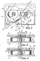
- FIGURE 1 is a top plan view of a belt driven tape cartridge, partially in section, containing the improved tape spool of the present invention;
- FIGURE 2 is a cross-sectional view of the spool of the present invention taken generally along the line 2-2 of FIGURE 1; and
- FIGURE 3 is an alternate embodiment of a tape spool for use in the cartridge of FIGURE 1.
- FIGURES 1 and 2 illustrate a data cartridge 10 of the type described in U.S. patent no. 3,692,255 (Von Behren) which includes a
thin base plate 12, usually of aluminum, and a clear or translucentpolymeric cover 14, which, when assembled, define a thin, generally rectangular enclosure. Enclosed within the data cartridge 10 are a pair oftape spools tape wrap pins tape guides magnetic recording tape 30, a driving belt 32, a pair ofbelt guide rollers belt driving roller 38. - The
tape spools cartridge base plate 12 for free rotation about spaced parallel axes. Themagnetic recording tape 30 is convolutely wound on thetape spools tape 30 guide path between thetape spools tape wrap pins tape guides - The cartridge 10 is formed with a
cutaway portion 40 along the tape path which provides access to themagnetic tape 30 by a magnetic transducer 42. Thecutaway portion 40 is normally closed by a spring-loadeddoor 44 which is opened as shown upon insertion of the data cartridge 10 into a tape recorder (not shown).second opening 46 is provided in thecartridge cover 14 to provide access to thebelt driving roller 38 by adrive roller 48 driven by areversible motor 50. The magnetic transducer 42, thedrive roller 48, and thereversible motor 50 are illustrated in phantom lines as they form a portion of the tape recorder rather than the data cartridge 10. The cartridgebelt driving roller 38 is provided with a reduced diameter 51 to prevent contact between the driving belt 32 and themagnetic recording tape 30. The driving belt 32 is thin, continuous, flexible and elastic. It has a uniform cross-sectional area and it extends around thebelt driving roller 38 and thebelt guide rollers tape 30 on thetape spools - The length of the belt 32 is less than the length of the path along which it extends so that when the belt 32 is stretched into position it will have an installed tension or pretension. The angle of wrap of the driving belt 32 at the
tape spools tape 30 wound on thetape spools tape 30 and thetape spools - Rotation of the
belt driving roller 38 in a counterclockwise direction (as viewed in FIGURE 1) by thedrive roller 48 causes the belt 32 to traverse its path in a counterclockwise direction and thetape 30 to move from thetape spool 18 to thetape spool 16, thetape spool 18 serving as a supply spool and thetape spool 16 serving as a take-up spool. Opposite rotation of thedriving roller 38 by thedrive roller 48 will cause tape to be supplied by thetape spool 16 and convolutely wound upon thetape spool 18. A predetermined frictional coupling between thebelt guide rollers guide belt rollers guide rollers spool 18 is increased compared to that at which it passes around thespool 16. This increased speed causes tension in thetape 30 as well as the ability to take up any slack developed in thetape 30 between thetape spools - The improved
tape spool upper flange 52 and alower flange 54 interconnected by ahub 56 providing a cylindricaltape winding surface 58. Thespool hub 56 andlower flange 54 molded as a single unit and theupper flange 52 molded separately and attached to thehub 56 either by an adhesive or welding. Thespool cartridge plate 12 to extend a predetermined distance above theplate 12. Thespool bore 64 provided in thehub 56, which bore is sized to closely but freely fit the diameter of the pin 60. - To reduce rotative friction of the
spool upper flange 52 is provided with a bearing protuberance 66 which extends into the hub bore 64 and contacts the pin 60. The bearing protuberance 66 is preferably frusto-conical or hemispherical in shape and preferably has arounded surface 68 which reduces the area of contact between the protuberance 66 and the pin 60. It will be recognized, however, that the protuberance 66 could simply be a cylindrical projection which contacts the pin 60 at a flat surface or the pin 60 could simply contact theflange 52. It is desirable, however, to include the bulk of material provided by the protuberance 66, rather than simply allowing the pin 60 to contact the flat, lower surface of theupper flange 52, because theupper flange 52 is molded of a polymer and may be somewhat abraded or frictionally heated by contact with the pin 60. The relatively large bulk of material provided by the protuberance 66 minimizes any damaging effects caused by such heating and the rounded shape of itssurface 68 further minimizes heat caused by friction and reduces abrasion caused by the pin 60. - In order to further reduce friction and abrasion generated between the pin 60 and the bearing protuberance 66, the terminal surface 70 of the pin 60 may likewise be rounded rather than flat as illustrated. The length of the pin 60, from the surface of the
cartridge plate 12 to its terminal end 70, is selected to be slightly greater than the length of the hub bore 64 from theflange 54 to the protuberance 66 so that thespool lower flange 54 rotates free of contact with thecartridge plate 12. - Thus far a
tape spool spool spool spool cartridge plate 12 and oscillating on the pin 60 astape 30 was being wound or removed. However, high speed rotation of thespools spool tape 30 upon thespool spool tape 30 by contact with theflanges - To minimize lifting and oscillation of the
spool upper flange 52 is further provided with a wear-button protuberance 72 extending from theflange 52 opposite and coaxial with the hub bore 64. Thecartridge cover 14 is provided with aspring 74 which contacts the wear-button protuberance 74 and urges the bearing protuberance 66 into contact with the pin 60. Although it might be possible to eliminate thespring 74 and allow the wear-button protuberance 74 to bear directly against thecover 14, such an arrangement would be difficult to achieve because tolerances would have to be controlled tightly and either a lack of contact between thecover 14 and thespool cover 14 and thespool spring 74 is, therefore, provided to provide resiliency and a limited amount of travel to compensate for tolerance variations in the length of the pin 60 and the manufacture of theupper flange 52. - The wear-button protuberance 72 is Provided to prevent contact between the
upper flange 52 and thecartridge cover 14 or thespring 74. The preferred shape of the wear-button protuberance 72 is frusto-conical or hemispherical and either shape preferably includes a roundedouter surface 76 to minimize the area of contact between the protuberance 72 and thespring 74. - The preferred type of
spring 74 is illustrated in FIGURES 1 and 2 and consists of double-cantilever spring arms area 82 and diametricallyopposed areas 84 and 86 of aspring mounting ring 88, which ring 88 is suitably attached to thecartridge cover 14. - The
spring arms arms spring 74. - FIGURE 3 illustrates an alternate embodiment of a
tape spool 90 according to the present invention in which a bearingprotuberance 92 and wear-button protuberance 94 are provided as opposite sides of aspherical ball 96 which is press-fitted, adhesively attached, or welded to acollar 98 which is in turn attached to theupper flange 100 of thespool 90 by an adhesive, welding or press-fitting. Thesphere 96 andcollar 98 may also be machined or molded as an integral unit of metal or plastic or thecollar 98 may be eliminated and thesphere 96 pressed or otherwise attached to theupper flange 100 by means of a hole in theflange 100 closely fitting the sphere. - Although the arrangement of FIGURE 3 requires a greater number of separate pieces and greater assembly than does the arrangement of FIGURE 2, the arrangement illustrated by FIGURE 3 may be advantageous in that the
sphere 96 which provides the bearing and wear-button protuberances upper flange 100. Thus thesphere 96 may be manufactured of a highly abrasion-resistant material, such as metal, acetal resin or polycarbonate, while theupper flange 100 is manufactured of a softer but more economical material such as acrylonitrile- butadiene-styrene copolymer or high-impact polystyrene. FIGURE 3 also illustrates an alternative to thespring 74 of FIGURE 2 by providing a straight leaf spring 102 which includes a mountingportion 104 and spring arms 106 (only one is shown) which extend from opposite ends of the mountingportion 104 to contact each of thespools portion 104 of the spring 102 may be attached to thecartridge cover 108 by any suitable method, but preferably is riveted thereto. It will be recognized that the leaf spring 102 of FIGURE 3 could be used in conjunction with thespool 18 or FIGURES 1 and 2. - Either of the alternate embodiments described herein is effective to greatly reduce friction between the rotating spool and its mounting pin and also to prevent oscillation of the spool relative to the pin. Although only two embodiments have been illustrated, it will be apparent to those skilled in the art that many modifications are possible. All of such modifications which fall within the spirit and scope of the appended claims are intended to be included in the present invention.
Claims (17)
wherein the extension of said pin (60) from said surface (12) is greater than the length of said bore (64) to said bearing protrusion (66) so that said spool is suspended above said surface for free rotation about said pin.
wherein the extension of said pin (60) from said one of said walls (12) is greater than the length of said bore (64) to said bearing protrusion (68) so that said spool (16, 18) is suspended above and may rotate free of contact with said one wall (12).
Applications Claiming Priority (2)
| Application Number | Priority Date | Filing Date | Title |
|---|---|---|---|
| US626138 | 1984-06-29 | ||
| US06/626,138 US4561609A (en) | 1984-06-29 | 1984-06-29 | Anti-friction and non-oscillating spool for belt driven cartridge |
Publications (2)
| Publication Number | Publication Date |
|---|---|
| EP0170403A1 true EP0170403A1 (en) | 1986-02-05 |
| EP0170403B1 EP0170403B1 (en) | 1989-12-27 |
Family
ID=24509107
Family Applications (1)
| Application Number | Title | Priority Date | Filing Date |
|---|---|---|---|
| EP85304569A Expired EP0170403B1 (en) | 1984-06-29 | 1985-06-26 | Anti-friction and non-oscillating spool for belt driven cartridge |
Country Status (13)
| Country | Link |
|---|---|
| US (1) | US4561609A (en) |
| EP (1) | EP0170403B1 (en) |
| JP (1) | JPH064474B2 (en) |
| KR (1) | KR930011382B1 (en) |
| AU (1) | AU572999B2 (en) |
| BR (1) | BR8503048A (en) |
| CA (1) | CA1242425A (en) |
| DE (1) | DE3575038D1 (en) |
| HK (1) | HK3691A (en) |
| IE (1) | IE56892B1 (en) |
| MX (1) | MX163535B (en) |
| NO (1) | NO169201C (en) |
| SG (1) | SG93390G (en) |
Cited By (2)
| Publication number | Priority date | Publication date | Assignee | Title |
|---|---|---|---|---|
| EP0466608A1 (en) * | 1990-07-13 | 1992-01-15 | Société Anonyme DYPY | Cassette for tape, comprising means for holding rotatable components mounted in the cassette in a predermined axial position |
| EP0572834A2 (en) * | 1992-06-03 | 1993-12-08 | Verbatim Corporation | Tape cartridge and method of making the same |
Families Citing this family (18)
| Publication number | Priority date | Publication date | Assignee | Title |
|---|---|---|---|---|
| JPS6047177U (en) * | 1983-09-09 | 1985-04-03 | ティーディーケイ株式会社 | magnetic tape cartridge |
| US4697759A (en) * | 1986-05-05 | 1987-10-06 | Cartrex | Reel for aligning tape path |
| JPH0514379Y2 (en) * | 1986-12-05 | 1993-04-16 | ||
| DE8808498U1 (en) * | 1988-07-02 | 1988-09-01 | Agfa-Gevaert Ag, 5090 Leverkusen | Magnetic tape cassette |
| US5092537A (en) * | 1989-10-05 | 1992-03-03 | Gigatek Memory Systems | Spring-loaded tape spool for belt-driven cartridge |
| US4986491A (en) * | 1989-12-28 | 1991-01-22 | Shape, Inc. | Reel leaf spring/cassette cover combinations and methods for assembly |
| US5142761A (en) * | 1989-12-28 | 1992-09-01 | Shape Inc. | Methods of assembling reel leaf spring/cassette cover combinations |
| US5544834A (en) * | 1990-11-19 | 1996-08-13 | Wti International Corporation | Video tape cassette |
| US5385782A (en) * | 1992-05-21 | 1995-01-31 | Minnesota Mining And Manufacturing Co. | Pre-coated data cartridge base plate |
| US5299086A (en) * | 1993-01-06 | 1994-03-29 | Verbatim Corporation | Low stiffness spring for drag induction and component retention in computer data cartridges |
| WO1995015560A1 (en) * | 1993-12-03 | 1995-06-08 | Jason Incorporated | Reel springs for magnetic tape cassettes |
| WO1995032503A1 (en) * | 1994-05-19 | 1995-11-30 | Minnesota Mining And Manufacturing Company | Tape guides for data cartridges |
| US5490029A (en) * | 1994-05-19 | 1996-02-06 | Minnesota Mining And Manufacturing Company | Compliant tape guide for data cartridges |
| US6095444A (en) * | 1996-01-24 | 2000-08-01 | Daiwa Seiko, Inc. | Attachment unit for a double bearing type reel for fishing |
| US6040966A (en) * | 1998-06-11 | 2000-03-21 | Imation Corp. | Data storage tape cartridge with hub alignment insert |
| US6045079A (en) * | 1998-08-14 | 2000-04-04 | Verbatim Corporation | Tape cartridge having a large door and pivotally mounted write protect arm |
| US6279846B1 (en) * | 1999-09-22 | 2001-08-28 | Imation Corp. | Data tape cartridge with modified hub mounting arrangement |
| US6318659B1 (en) | 2000-06-27 | 2001-11-20 | Imation Corp. | Tape reel assembly with hub sleeve for a data storage tape cartridge |
Citations (5)
| Publication number | Priority date | Publication date | Assignee | Title |
|---|---|---|---|---|
| US3692255A (en) * | 1971-06-17 | 1972-09-19 | Minnesota Mining & Mfg | Belt driven tape cartridge |
| US3925820A (en) * | 1972-08-24 | 1975-12-09 | Sony Corp | Endless loop tape cartridge for use with tape extraction systems |
| DE3201642A1 (en) * | 1981-01-20 | 1982-09-23 | Victor Company Of Japan, Ltd., Yokohama, Kanagawa | TAPE CASSETTE |
| EP0070616A1 (en) * | 1981-05-27 | 1983-01-26 | Technicolor, Inc. | Improved cassette hub locking mechanism |
| EP0072517A2 (en) * | 1981-08-18 | 1983-02-23 | Agfa-Gevaert AG | Reel for video cassettes |
Family Cites Families (7)
| Publication number | Priority date | Publication date | Assignee | Title |
|---|---|---|---|---|
| US2894700A (en) * | 1956-04-30 | 1959-07-14 | Dictaphone Corp | Portable dictation apparatus |
| JPS52110603A (en) * | 1976-03-13 | 1977-09-16 | Rundofunku Unto Fuerunzetekuni | Method and device for transmitting electroacoustic sound in directional high fidelity |
| JPS5815202B2 (en) * | 1976-05-19 | 1983-03-24 | 株式会社東芝 | Coiling temperature control method for hot-rolled steel sheets |
| JPS5455959A (en) * | 1977-10-04 | 1979-05-04 | Nachi Fujikoshi Corp | Industrial robot with means for compensating motion of wrist |
| US4289282A (en) * | 1979-03-01 | 1981-09-15 | Dai-Ichi Seiko Co., Ltd. | Tape reel |
| JPS6331267Y2 (en) * | 1981-06-18 | 1988-08-22 | ||
| US4452404A (en) * | 1982-08-20 | 1984-06-05 | Shape Inc. | Tape reel hub assembly |
-
1984
- 1984-06-29 US US06/626,138 patent/US4561609A/en not_active Expired - Lifetime
-
1985
- 1985-05-21 AU AU42695/85A patent/AU572999B2/en not_active Ceased
- 1985-05-22 IE IE1275/85A patent/IE56892B1/en not_active IP Right Cessation
- 1985-05-23 CA CA000482131A patent/CA1242425A/en not_active Expired
- 1985-06-10 MX MX205598A patent/MX163535B/en unknown
- 1985-06-24 KR KR1019850004468A patent/KR930011382B1/en not_active IP Right Cessation
- 1985-06-25 BR BR8503048A patent/BR8503048A/en not_active IP Right Cessation
- 1985-06-26 EP EP85304569A patent/EP0170403B1/en not_active Expired
- 1985-06-26 DE DE8585304569T patent/DE3575038D1/en not_active Expired - Lifetime
- 1985-06-26 NO NO852573A patent/NO169201C/en unknown
- 1985-06-28 JP JP60140736A patent/JPH064474B2/en not_active Expired - Lifetime
-
1990
- 1990-11-19 SG SG933/90A patent/SG93390G/en unknown
-
1991
- 1991-01-10 HK HK36/91A patent/HK3691A/en not_active IP Right Cessation
Patent Citations (5)
| Publication number | Priority date | Publication date | Assignee | Title |
|---|---|---|---|---|
| US3692255A (en) * | 1971-06-17 | 1972-09-19 | Minnesota Mining & Mfg | Belt driven tape cartridge |
| US3925820A (en) * | 1972-08-24 | 1975-12-09 | Sony Corp | Endless loop tape cartridge for use with tape extraction systems |
| DE3201642A1 (en) * | 1981-01-20 | 1982-09-23 | Victor Company Of Japan, Ltd., Yokohama, Kanagawa | TAPE CASSETTE |
| EP0070616A1 (en) * | 1981-05-27 | 1983-01-26 | Technicolor, Inc. | Improved cassette hub locking mechanism |
| EP0072517A2 (en) * | 1981-08-18 | 1983-02-23 | Agfa-Gevaert AG | Reel for video cassettes |
Cited By (4)
| Publication number | Priority date | Publication date | Assignee | Title |
|---|---|---|---|---|
| EP0466608A1 (en) * | 1990-07-13 | 1992-01-15 | Société Anonyme DYPY | Cassette for tape, comprising means for holding rotatable components mounted in the cassette in a predermined axial position |
| FR2664731A1 (en) * | 1990-07-13 | 1992-01-17 | Dypy Sa | DEVICE FOR HOLDING ROTARY CASSETTE ELEMENTS CONTAINING A RIBBON. |
| EP0572834A2 (en) * | 1992-06-03 | 1993-12-08 | Verbatim Corporation | Tape cartridge and method of making the same |
| EP0572834A3 (en) * | 1992-06-03 | 1995-01-18 | Verbatim Corp | Tape cartridge and method of making the same. |
Also Published As
| Publication number | Publication date |
|---|---|
| KR930011382B1 (en) | 1993-12-04 |
| CA1242425A (en) | 1988-09-27 |
| JPS6118682A (en) | 1986-01-27 |
| IE56892B1 (en) | 1992-01-15 |
| DE3575038D1 (en) | 1990-02-01 |
| IE851275L (en) | 1985-12-29 |
| US4561609A (en) | 1985-12-31 |
| KR860000651A (en) | 1986-01-30 |
| JPH064474B2 (en) | 1994-01-19 |
| EP0170403B1 (en) | 1989-12-27 |
| NO169201C (en) | 1992-05-20 |
| BR8503048A (en) | 1986-03-11 |
| AU4269585A (en) | 1986-01-02 |
| AU572999B2 (en) | 1988-05-26 |
| MX163535B (en) | 1992-05-26 |
| SG93390G (en) | 1991-02-14 |
| NO169201B (en) | 1992-02-10 |
| HK3691A (en) | 1991-01-18 |
| NO852573L (en) | 1985-12-30 |
Similar Documents
| Publication | Publication Date | Title |
|---|---|---|
| US4561609A (en) | Anti-friction and non-oscillating spool for belt driven cartridge | |
| CA1242177A (en) | Non-oscillating spool for belt driven cartridge | |
| US4607808A (en) | Wear-resistant capstan for belt driven cartridge | |
| US4571789A (en) | Snap fastener for belt driven cartridge | |
| US5893526A (en) | Tape guides for data cartridges | |
| US6405957B1 (en) | Data storage tape cartridge and tape path with an idler wrap guide for reduced lateral tape movement | |
| US4729500A (en) | Construction of a tape guide roller for a videocassette recorder | |
| KR860007647A (en) | Disk Drive Combined Tape Cartridge | |
| US5677817A (en) | Guide roller for a tape driving belt in a data storage cartridge | |
| US5490029A (en) | Compliant tape guide for data cartridges | |
| US5092537A (en) | Spring-loaded tape spool for belt-driven cartridge | |
| JPH1186494A (en) | Corner roller and tape cartridge having the same | |
| US5702065A (en) | Tape cartridge with reduced tangential drive force | |
| US5703741A (en) | Belt-driven tape cartridge with tape vibration damping pin | |
| EP0667617B1 (en) | Belt driver tape cartridge | |
| US5716018A (en) | Tape guide for digital data tape mini-cartridge | |
| US5765772A (en) | Data cartridge corner roller with stepped bore | |
| US4813628A (en) | Slack limiter for a magnetic tape cassette | |
| US3685754A (en) | Tape cartridge | |
| US5601248A (en) | Tape guide for digital data tape mini-cartridge | |
| JPH11126453A (en) | Corner roller and tape cartridge equipped therewith | |
| JPH0745031A (en) | Tape cartridge | |
| JPH04172677A (en) | Tape cartridge | |
| KR870002577A (en) | Magnetic tape cartridge | |
| JPH0644732A (en) | Tape cartridge |
Legal Events
| Date | Code | Title | Description |
|---|---|---|---|
| PUAI | Public reference made under article 153(3) epc to a published international application that has entered the european phase |
Free format text: ORIGINAL CODE: 0009012 |
|
| AK | Designated contracting states |
Designated state(s): DE FR GB IT |
|
| 17P | Request for examination filed |
Effective date: 19860505 |
|
| 17Q | First examination report despatched |
Effective date: 19880122 |
|
| ITF | It: translation for a ep patent filed | ||
| GRAA | (expected) grant |
Free format text: ORIGINAL CODE: 0009210 |
|
| AK | Designated contracting states |
Kind code of ref document: B1 Designated state(s): DE FR GB IT |
|
| REF | Corresponds to: |
Ref document number: 3575038 Country of ref document: DE Date of ref document: 19900201 |
|
| ET | Fr: translation filed | ||
| PLBE | No opposition filed within time limit |
Free format text: ORIGINAL CODE: 0009261 |
|
| STAA | Information on the status of an ep patent application or granted ep patent |
Free format text: STATUS: NO OPPOSITION FILED WITHIN TIME LIMIT |
|
| 26N | No opposition filed | ||
| ITTA | It: last paid annual fee | ||
| REG | Reference to a national code |
Ref country code: FR Ref legal event code: CL |
|
| PGFP | Annual fee paid to national office [announced via postgrant information from national office to epo] |
Ref country code: DE Payment date: 19950526 Year of fee payment: 11 |
|
| PG25 | Lapsed in a contracting state [announced via postgrant information from national office to epo] |
Ref country code: DE Effective date: 19970301 |
|
| PGFP | Annual fee paid to national office [announced via postgrant information from national office to epo] |
Ref country code: GB Payment date: 19970506 Year of fee payment: 13 |
|
| PGFP | Annual fee paid to national office [announced via postgrant information from national office to epo] |
Ref country code: FR Payment date: 19980603 Year of fee payment: 14 |
|
| PG25 | Lapsed in a contracting state [announced via postgrant information from national office to epo] |
Ref country code: GB Free format text: LAPSE BECAUSE OF NON-PAYMENT OF DUE FEES Effective date: 19980626 |
|
| GBPC | Gb: european patent ceased through non-payment of renewal fee |
Effective date: 19980626 |
|
| PG25 | Lapsed in a contracting state [announced via postgrant information from national office to epo] |
Ref country code: FR Free format text: THE PATENT HAS BEEN ANNULLED BY A DECISION OF A NATIONAL AUTHORITY Effective date: 19990630 |
|
| REG | Reference to a national code |
Ref country code: FR Ref legal event code: ST |