EP0170131A2 - Internal combustion engine with intake ducts arranged to produce high turbulence in the feed air flow - Google Patents
Internal combustion engine with intake ducts arranged to produce high turbulence in the feed air flow Download PDFInfo
- Publication number
- EP0170131A2 EP0170131A2 EP85108689A EP85108689A EP0170131A2 EP 0170131 A2 EP0170131 A2 EP 0170131A2 EP 85108689 A EP85108689 A EP 85108689A EP 85108689 A EP85108689 A EP 85108689A EP 0170131 A2 EP0170131 A2 EP 0170131A2
- Authority
- EP
- European Patent Office
- Prior art keywords
- intake
- cylinder
- engine
- volute
- ports
- Prior art date
- Legal status (The legal status is an assumption and is not a legal conclusion. Google has not performed a legal analysis and makes no representation as to the accuracy of the status listed.)
- Granted
Links
Images
Classifications
-
- F—MECHANICAL ENGINEERING; LIGHTING; HEATING; WEAPONS; BLASTING
- F02—COMBUSTION ENGINES; HOT-GAS OR COMBUSTION-PRODUCT ENGINE PLANTS
- F02B—INTERNAL-COMBUSTION PISTON ENGINES; COMBUSTION ENGINES IN GENERAL
- F02B31/00—Modifying induction systems for imparting a rotation to the charge in the cylinder
-
- F—MECHANICAL ENGINEERING; LIGHTING; HEATING; WEAPONS; BLASTING
- F02—COMBUSTION ENGINES; HOT-GAS OR COMBUSTION-PRODUCT ENGINE PLANTS
- F02F—CYLINDERS, PISTONS OR CASINGS, FOR COMBUSTION ENGINES; ARRANGEMENTS OF SEALINGS IN COMBUSTION ENGINES
- F02F1/00—Cylinders; Cylinder heads
- F02F1/24—Cylinder heads
- F02F1/42—Shape or arrangement of intake or exhaust channels in cylinder heads
- F02F1/4228—Helically-shaped channels
-
- F—MECHANICAL ENGINEERING; LIGHTING; HEATING; WEAPONS; BLASTING
- F02—COMBUSTION ENGINES; HOT-GAS OR COMBUSTION-PRODUCT ENGINE PLANTS
- F02B—INTERNAL-COMBUSTION PISTON ENGINES; COMBUSTION ENGINES IN GENERAL
- F02B2275/00—Other engines, components or details, not provided for in other groups of this subclass
- F02B2275/14—Direct injection into combustion chamber
-
- F—MECHANICAL ENGINEERING; LIGHTING; HEATING; WEAPONS; BLASTING
- F02—COMBUSTION ENGINES; HOT-GAS OR COMBUSTION-PRODUCT ENGINE PLANTS
- F02B—INTERNAL-COMBUSTION PISTON ENGINES; COMBUSTION ENGINES IN GENERAL
- F02B3/00—Engines characterised by air compression and subsequent fuel addition
- F02B3/06—Engines characterised by air compression and subsequent fuel addition with compression ignition
-
- Y—GENERAL TAGGING OF NEW TECHNOLOGICAL DEVELOPMENTS; GENERAL TAGGING OF CROSS-SECTIONAL TECHNOLOGIES SPANNING OVER SEVERAL SECTIONS OF THE IPC; TECHNICAL SUBJECTS COVERED BY FORMER USPC CROSS-REFERENCE ART COLLECTIONS [XRACs] AND DIGESTS
- Y02—TECHNOLOGIES OR APPLICATIONS FOR MITIGATION OR ADAPTATION AGAINST CLIMATE CHANGE
- Y02T—CLIMATE CHANGE MITIGATION TECHNOLOGIES RELATED TO TRANSPORTATION
- Y02T10/00—Road transport of goods or passengers
- Y02T10/10—Internal combustion engine [ICE] based vehicles
- Y02T10/12—Improving ICE efficiencies
Definitions
- This invention relates to a high-turbulence internal combustion engine, in particular of the high-speed diesel type, which is provided with intake ducts configured in such a manner as to be able to produce high vorticity in the engine feed air flow.
- intake ducts configured in such a manner as to be able to produce high vorticity in the engine feed air flow.
- numerous expedients are known such as providing the intake valve of each engine cylinder with a deflector fin, or using volute-shaped intake ducts.
- These systems well known to experts of the art, enable the desired vorticity index to be obtained, but have the serious drawback of being incapable of adjusting the vorticity index to the engine rotational speed.
- vorticity indices are obtained which are ideal only for a limited range of engine operation, whereas when the engine rotational speed lies outside this range, the vorticity does not adapt to the required engine characteristics.
- the object of the present invention is to provide an internal combustion engine comprising intake ducts of a geometry such as to produce high vorticity in the engine feed air flow and to adjust the vorticity index to the optimum value for the various engine rotational speeds.
- a high turbulence internal combustion engine particularly of the high-speed direct injection diesel type, comprising a first and a second combustion chamber which are side-by-side and are each provided with a respective intake port and a respective exhaust port, and a cylinder head in which there are provided said ports and at least one first intake duct of volute type connected to said intake port of said first combustion chamber, and a second intake duct of volute type connected to said intake port of said second combustion chamber, characterised in that said intake ports and said first and second intake duct of said first and second chamber are disposed in adjacent side-by-side positions between the respective said exhaust ports of said first and second chamber, said first and second volute duct being orientated in the reverse direction to each other and said cylinder head comprising means for connecting together said first and second volute duct.
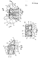
- the reference numeral 1 indicates overall an internal combustion engine of any known type, for example a high-speed direct injection diesel engine, of which there are shown for simplicity only part of the cylinder head 2 and, by dashed lines, a pair of side-by-side combustion chambers 3 and 4 defined by respective cylinders 5 and 6 formed in the cylinder block, not shown for simplicity, and by the cylinder head 2.
- the engine 1 must be of the type comprising an even number of cylinders divided into one or more pairs of side-by-side cylinders 5 and 6, as shown in Figure 1.
- Each chamber 3 and 4 is provided with a respective intake port 7 end with a respective exhaust port 8 provided in the cylinder head 2 and closable ( Figure 3) by respective valves 9 slidable in guides 10 in the cylinder head 2 and operated in known manner, not shown for simplicity.
- the cylinder head 2 is also provided with exhaust ducts, not shown for simplicity, and with at least one pair of intake ducts 11 and 12 of the volute type, which are connected respectively to the intake ports 7 of the respective cylinders 5 and 6.
- the intake ports 7 and the volute intake ducts 11 and 12 of each pair of chambers 3 and 4 are disposed in adjacent, side-by-side positions between the respective exhaust ports 8 of the side-by-side chambers 3 and 4, and the volute ducts 11 and 12 have the same geometry and the same dimensions but are orientated in different directions to each other.
- the duct 11 is formed with a volute 13 which winds anticlockwise
- the duct 12 is formed with a volute 14 which winds clockwise.
- the volutes 13 and 14 are disposed in positions corresponding with the adjacent intake ports 7, coaxially thereto and above them, and constitute the terminal part of the ducts 11 and 12, which are connected in known manner, not shown for simplicity, to the feed manifold of the engine 1.
- the cylinder head 2 also comprises at least one cavity arranged to connect together the opposing volute intake ducts 11 and 12 of each pair of side-by-side cylinders 5 and 6.
- the cylinder head 2 is provided with two respective cavities 15 and 16 for each pair of side-by-side cylinders 5 and 6, formed in positions corresponding with the intake ports 7, exactly between the volutes 13 and 14, to define a pair of tangential communication ports 18 and 19 which connect the ducts 11 and 12 together at the volutes 13 and 14.
- the port 18 peripherally connects a terminal part 20 of each volute 13 and 14 together, and is substantially rectilinear and disposed transversely to the axis of the cylinders 5 and 6, whereas the port 19 connects together respective mouth zones 21 of the volutes 13 and 14 and is defined by respective curved surfaces 22 directed tangentially to the volutes 13 and 14.
- the engine timing and the movement of the pistons (not shown for simplicity) of the cylinders 5 and 6 are such that the thermodynamic cycles of each cylinder 5 and 6 of the pair (or of each pair in the case of an engine with four or more cylinders) of side-by-side cylinders are staggered by an extent such as to maintain the intake port 7 of the cylinder 5 closed when the intake port of the cylinder 6 is open and vice versa.
- each cylinder 5 and 6 of each pair of side-by-side cylinders of the engine 1 is served by both intake ducts 11 and 12, in that these latter are connected together by the ports 18 and 19 and only one of the intake ports 7 of the cylinders 5 and 6 is open during the intake stage of each cylinder.
- the shape, dimensions and position of the ducts 11 and 12 and ports 18 and 19 have been determined such that said ducts and the cavities 15 and 16 are able to be produced by using a single core during the casting of the cylinder head 2.
- the constructional precision of the engine cylinder heads 2 formed according to the invention is increased in that as the intake ducts of each pair of side-by-side cylinders are connected together, there are no longer any errors due to deformation or to incorrect positioning of the cores for the ducts during said casting of the cylinder head 2.
- the secondary feed air flow originating from the duct 11 is introduced tangentially into the volute 14 besides being introduced into its mouth zone 21, thus favouring not only said oscillatory phenomena in the ducts but also the generation of feed air flow turbulence inside said volute and its preservation as the rotational speed of the engine 1 varies.
- these phenomena can be intensified, particularly at low rotational speeds, thus enabling homogeneous mixing of air and fuel to be obtained for each rotational speed of the engine 1.
Landscapes
- Engineering & Computer Science (AREA)
- Chemical & Material Sciences (AREA)
- Combustion & Propulsion (AREA)
- Mechanical Engineering (AREA)
- General Engineering & Computer Science (AREA)
- Cylinder Crankcases Of Internal Combustion Engines (AREA)
Abstract
Description
- This invention relates to a high-turbulence internal combustion engine, in particular of the high-speed diesel type, which is provided with intake ducts configured in such a manner as to be able to produce high vorticity in the engine feed air flow. In internal combustion engines, and in particular in small- displacement diesel engines, it is particularly important to feed the air with the correct degree of turbulence in order to obtain uniform mixing of air and fuel. To attain this, numerous expedients are known such as providing the intake valve of each engine cylinder with a deflector fin, or using volute-shaped intake ducts. These systems, well known to experts of the art, enable the desired vorticity index to be obtained, but have the serious drawback of being incapable of adjusting the vorticity index to the engine rotational speed. Basically, with the aforesaid systems, vorticity indices are obtained which are ideal only for a limited range of engine operation, whereas when the engine rotational speed lies outside this range, the vorticity does not adapt to the required engine characteristics.
- The object of the present invention is to provide an internal combustion engine comprising intake ducts of a geometry such as to produce high vorticity in the engine feed air flow and to adjust the vorticity index to the optimum value for the various engine rotational speeds.
- Said object is attained according to the present invention by a high turbulence internal combustion engine, particularly of the high-speed direct injection diesel type, comprising a first and a second combustion chamber which are side-by-side and are each provided with a respective intake port and a respective exhaust port, and a cylinder head in which there are provided said ports and at least one first intake duct of volute type connected to said intake port of said first combustion chamber, and a second intake duct of volute type connected to said intake port of said second combustion chamber, characterised in that said intake ports and said first and second intake duct of said first and second chamber are disposed in adjacent side-by-side positions between the respective said exhaust ports of said first and second chamber, said first and second volute duct being orientated in the reverse direction to each other and said cylinder head comprising means for connecting together said first and second volute duct.
- The present invention will be apparent from the non-limiting description of one embodiment thereof given hereinafter with reference to the accompanying drawing, in which:
- Figure 1 is a partially sectional, simplified plan view of an internal combustion engine constructed in accordance with the present invention; and
- Figures 2 and 3 are respective sections on the lines II and III of the engine of Figure 1.
- In Figures 1 and 2, the reference numeral 1 indicates overall an internal combustion engine of any known type, for example a high-speed direct injection diesel engine, of which there are shown for simplicity only part of the
cylinder head 2 and, by dashed lines, a pair of side-by-side combustion chambers 3 and 4 defined byrespective cylinders 5 and 6 formed in the cylinder block, not shown for simplicity, and by thecylinder head 2. According to the invention, the engine 1 must be of the type comprising an even number of cylinders divided into one or more pairs of side-by-side cylinders 5 and 6, as shown in Figure 1. Eachchamber 3 and 4 is provided with arespective intake port 7 end with a respective exhaust port 8 provided in thecylinder head 2 and closable (Figure 3) by respective valves 9 slidable inguides 10 in thecylinder head 2 and operated in known manner, not shown for simplicity. Thecylinder head 2 is also provided with exhaust ducts, not shown for simplicity, and with at least one pair ofintake ducts 11 and 12 of the volute type, which are connected respectively to theintake ports 7 of therespective cylinders 5 and 6. - According to the invention the
intake ports 7 and thevolute intake ducts 11 and 12 of each pair of chambers 3 and 4 (or of cylinders 5 and 6) are disposed in adjacent, side-by-side positions between the respective exhaust ports 8 of the side-by-side chambers 3 and 4, and thevolute ducts 11 and 12 have the same geometry and the same dimensions but are orientated in different directions to each other. For example, the duct 11 is formed with avolute 13 which winds anticlockwise, whereas theduct 12 is formed with avolute 14 which winds clockwise. Thevolutes adjacent intake ports 7, coaxially thereto and above them, and constitute the terminal part of theducts 11 and 12, which are connected in known manner, not shown for simplicity, to the feed manifold of the engine 1. According to the invention, thecylinder head 2 also comprises at least one cavity arranged to connect together the opposingvolute intake ducts 11 and 12 of each pair of side-by-side cylinders 5 and 6. In particular, thecylinder head 2 is provided with tworespective cavities 15 and 16 for each pair of side-by-side cylinders 5 and 6, formed in positions corresponding with theintake ports 7, exactly between thevolutes tangential communication ports ducts 11 and 12 together at thevolutes - According to the invention, the
port 18 peripherally connects aterminal part 20 of eachvolute cylinders 5 and 6, whereas theport 19 connects togetherrespective mouth zones 21 of thevolutes curved surfaces 22 directed tangentially to thevolutes cylinders 5 and 6 are such that the thermodynamic cycles of eachcylinder 5 and 6 of the pair (or of each pair in the case of an engine with four or more cylinders) of side-by-side cylinders are staggered by an extent such as to maintain theintake port 7 of the cylinder 5 closed when the intake port of thecylinder 6 is open and vice versa. In this manner, eachcylinder 5 and 6 of each pair of side-by-side cylinders of the engine 1 is served by bothintake ducts 11 and 12, in that these latter are connected together by theports intake ports 7 of thecylinders 5 and 6 is open during the intake stage of each cylinder. - The shape of the
ducts 11 and 12 andrelative volutes - Furthermore according to the invention, the shape, dimensions and position of the
ducts 11 and 12 andports cavities 15 and 16 are able to be produced by using a single core during the casting of thecylinder head 2. In this manner, as theducts 11 and 12 are formed simultaneously, the constructional precision of theengine cylinder heads 2 formed according to the invention is increased in that as the intake ducts of each pair of side-by-side cylinders are connected together, there are no longer any errors due to deformation or to incorrect positioning of the cores for the ducts during said casting of thecylinder head 2. - The operation of the described engine 1 is as follows. Considering a pair of side-by-
side cylinders 5 and 6 with theirintake ports 7 connected together by theducts 11 and 12 andports cylinder 6 is in the intake stage, ie with theport 7 open and consequently the cylinder 5 has itsport 7 closed, for example exhausting, the feed air flow shown by arrows in Figure 1 is drawn mainly through theduct 12 closer to theopen port 7, and partly through the duct 11 which, by communicating with theduct 12 through theports duct 12 by the opening of theport 7. Consequently, a main feed air flow enters thevolute 14 through theduct 12 and is caused to rotate thereby in known manner before being fed into thecylinder 6 through theport 7, and a second feed air flow drawn through the duct 11 is fed into thevolute 13 where it is also rotated and where, finding theport 7 of this latter closed, favours the generation, by virtue of the presence of theports ducts 11 and 12. Subsequently, the secondary air flow is also drawn in through theport 7 of thecylinder 6 by passing into thevolute 14 throughsaid ports port 19 and the profile of thesurfaces 22 defining theport 18, which is also tangential to thevolutes volute 14 besides being introduced into itsmouth zone 21, thus favouring not only said oscillatory phenomena in the ducts but also the generation of feed air flow turbulence inside said volute and its preservation as the rotational speed of the engine 1 varies. By properly dimensioning theducts 11 and 12, these phenomena can be intensified, particularly at low rotational speeds, thus enabling homogeneous mixing of air and fuel to be obtained for each rotational speed of the engine 1. Moreover, as the cross-section of the intake duct in the engine according to the invention is substantially increased (as both the intake ducts of each pair of adjacent cylinders serve each cylinder), a reduction in the air velocity at thevolutes cylinder 6 is clearly also applicable to the cylinder 5 when itsport 7 opens, with simultaneous closure of theport 7 of thecylinder 6 because of said staggering of their thermodynamic cycles. The advantages of the present invention are apparent from the description, and it is apparent that modifications can be made thereto wihtout leaving the scope of said invention.
Claims (6)
Applications Claiming Priority (2)
| Application Number | Priority Date | Filing Date | Title |
|---|---|---|---|
| IT67748/84A IT1180088B (en) | 1984-07-27 | 1984-07-27 | ENDOTHERMAL ENGINE WITH INTAKE DUCTS SUITABLE TO PRODUCE HIGH TURBULENCE IN THE SUPPLY AIRFLOW |
| IT6774884 | 1984-07-27 |
Publications (3)
| Publication Number | Publication Date |
|---|---|
| EP0170131A2 true EP0170131A2 (en) | 1986-02-05 |
| EP0170131A3 EP0170131A3 (en) | 1987-01-14 |
| EP0170131B1 EP0170131B1 (en) | 1989-10-04 |
Family
ID=11304985
Family Applications (1)
| Application Number | Title | Priority Date | Filing Date |
|---|---|---|---|
| EP85108689A Expired EP0170131B1 (en) | 1984-07-27 | 1985-07-11 | Internal combustion engine with intake ducts arranged to produce high turbulence in the feed air flow |
Country Status (4)
| Country | Link |
|---|---|
| EP (1) | EP0170131B1 (en) |
| DE (1) | DE3573449D1 (en) |
| ES (1) | ES8608095A1 (en) |
| IT (1) | IT1180088B (en) |
Cited By (1)
| Publication number | Priority date | Publication date | Assignee | Title |
|---|---|---|---|---|
| US4945873A (en) * | 1988-12-02 | 1990-08-07 | Avl Gesellschaft Fur Verbrennungskraftmaschinen Und Messtechnik M.B.H. Prof. Dr.Dr.H.C. Hans List | Internal combustion engine with two inlet valves per cylinder |
Citations (3)
| Publication number | Priority date | Publication date | Assignee | Title |
|---|---|---|---|---|
| GB825837A (en) * | 1955-10-12 | 1959-12-23 | Henry Weslake | Improvements in or relating to inlet passages for internal combustion engines |
| FR2359972A1 (en) * | 1976-07-26 | 1978-02-24 | Int Harvester Co | Air induction system for IC engines - has main induction pipes joined by auxiliary pipe to superimpose spiral air flow |
| DE2921300A1 (en) * | 1978-06-15 | 1979-12-20 | Toyota Motor Co Ltd | Induced swirl IC piston engine - has throttle valve and contoured vane in inlet duct to produce eccentric gas flow |
-
1984
- 1984-07-27 IT IT67748/84A patent/IT1180088B/en active
-
1985
- 1985-07-11 EP EP85108689A patent/EP0170131B1/en not_active Expired
- 1985-07-11 DE DE8585108689T patent/DE3573449D1/en not_active Expired
- 1985-07-26 ES ES545567A patent/ES8608095A1/en not_active Expired
Patent Citations (3)
| Publication number | Priority date | Publication date | Assignee | Title |
|---|---|---|---|---|
| GB825837A (en) * | 1955-10-12 | 1959-12-23 | Henry Weslake | Improvements in or relating to inlet passages for internal combustion engines |
| FR2359972A1 (en) * | 1976-07-26 | 1978-02-24 | Int Harvester Co | Air induction system for IC engines - has main induction pipes joined by auxiliary pipe to superimpose spiral air flow |
| DE2921300A1 (en) * | 1978-06-15 | 1979-12-20 | Toyota Motor Co Ltd | Induced swirl IC piston engine - has throttle valve and contoured vane in inlet duct to produce eccentric gas flow |
Cited By (1)
| Publication number | Priority date | Publication date | Assignee | Title |
|---|---|---|---|---|
| US4945873A (en) * | 1988-12-02 | 1990-08-07 | Avl Gesellschaft Fur Verbrennungskraftmaschinen Und Messtechnik M.B.H. Prof. Dr.Dr.H.C. Hans List | Internal combustion engine with two inlet valves per cylinder |
Also Published As
| Publication number | Publication date |
|---|---|
| EP0170131B1 (en) | 1989-10-04 |
| IT8467748A1 (en) | 1986-01-27 |
| ES8608095A1 (en) | 1986-06-16 |
| DE3573449D1 (en) | 1989-11-09 |
| ES545567A0 (en) | 1986-06-16 |
| EP0170131A3 (en) | 1987-01-14 |
| IT1180088B (en) | 1987-09-23 |
| IT8467748A0 (en) | 1984-07-27 |
Similar Documents
| Publication | Publication Date | Title |
|---|---|---|
| US4763612A (en) | Intake system for internal combustion engine | |
| US4649876A (en) | Intake means of internal combustion engine | |
| EP0330302B1 (en) | Engine with variable area intake passages | |
| US4240387A (en) | Intake system of a multi-cylinder internal combustion engine | |
| US4617896A (en) | Internal combustion engine having three intake valves per cylinder | |
| US4809647A (en) | Intake system for multi cylindered engine | |
| US4766853A (en) | Intake passage for multi-cylinder engine | |
| US5762036A (en) | Split plenum intake manifold with variable runners | |
| US4972814A (en) | Combustion system of an internal combustion engine | |
| EP0413316A1 (en) | Exhaust control valve system for parallel multi-cylinder two-cycle engine | |
| US4771740A (en) | Intake system for internal combustion engine | |
| US4370955A (en) | Rotary valve for an internal combustion engine | |
| US4898144A (en) | Intake system for internal combustion engine | |
| EP0074202A2 (en) | Inlet air swirl control means for I.C. engines | |
| US5010854A (en) | Intake apparatus for V-type 8-cyl internal combustion engine | |
| US4660530A (en) | Intake system for internal combustion engine | |
| JPH04231618A (en) | Improvement of 2-cycle reciprocating motion internal combustion engine | |
| US5673656A (en) | Cylinder head for a four stroke combustion engine | |
| US4300500A (en) | Intake system of a multi-cylinder internal combustion engine | |
| EP0170131B1 (en) | Internal combustion engine with intake ducts arranged to produce high turbulence in the feed air flow | |
| US4519363A (en) | Intake system for an internal combustion engine provided with several intake valves | |
| US4886021A (en) | Multi-cylindered two stroke cycle engines | |
| CN217107241U (en) | Engine cylinder cover, engine and automobile | |
| US4744342A (en) | Intake port structure for an internal combustion engine | |
| KR19990029142A (en) | Manufacturing method of cylinder head of internal combustion engine |
Legal Events
| Date | Code | Title | Description |
|---|---|---|---|
| PUAI | Public reference made under article 153(3) epc to a published international application that has entered the european phase |
Free format text: ORIGINAL CODE: 0009012 |
|
| AK | Designated contracting states |
Designated state(s): DE FR GB |
|
| PUAL | Search report despatched |
Free format text: ORIGINAL CODE: 0009013 |
|
| AK | Designated contracting states |
Kind code of ref document: A3 Designated state(s): DE FR GB |
|
| 17P | Request for examination filed |
Effective date: 19870512 |
|
| 17Q | First examination report despatched |
Effective date: 19871125 |
|
| GRAA | (expected) grant |
Free format text: ORIGINAL CODE: 0009210 |
|
| AK | Designated contracting states |
Kind code of ref document: B1 Designated state(s): DE FR GB |
|
| REF | Corresponds to: |
Ref document number: 3573449 Country of ref document: DE Date of ref document: 19891109 |
|
| ET | Fr: translation filed | ||
| PLBE | No opposition filed within time limit |
Free format text: ORIGINAL CODE: 0009261 |
|
| STAA | Information on the status of an ep patent application or granted ep patent |
Free format text: STATUS: NO OPPOSITION FILED WITHIN TIME LIMIT |
|
| 26N | No opposition filed | ||
| PGFP | Annual fee paid to national office [announced via postgrant information from national office to epo] |
Ref country code: FR Payment date: 19930610 Year of fee payment: 9 |
|
| PGFP | Annual fee paid to national office [announced via postgrant information from national office to epo] |
Ref country code: GB Payment date: 19930614 Year of fee payment: 9 |
|
| PGFP | Annual fee paid to national office [announced via postgrant information from national office to epo] |
Ref country code: DE Payment date: 19930920 Year of fee payment: 9 |
|
| PG25 | Lapsed in a contracting state [announced via postgrant information from national office to epo] |
Ref country code: GB Effective date: 19940711 |
|
| GBPC | Gb: european patent ceased through non-payment of renewal fee |
Effective date: 19940711 |
|
| PG25 | Lapsed in a contracting state [announced via postgrant information from national office to epo] |
Ref country code: FR Effective date: 19950331 |
|
| PG25 | Lapsed in a contracting state [announced via postgrant information from national office to epo] |
Ref country code: DE Effective date: 19950401 |
|
| REG | Reference to a national code |
Ref country code: FR Ref legal event code: ST |