EP0170025A1 - Apparatus for fitting a tubular filter element in a shell - Google Patents
Apparatus for fitting a tubular filter element in a shell Download PDFInfo
- Publication number
- EP0170025A1 EP0170025A1 EP85107504A EP85107504A EP0170025A1 EP 0170025 A1 EP0170025 A1 EP 0170025A1 EP 85107504 A EP85107504 A EP 85107504A EP 85107504 A EP85107504 A EP 85107504A EP 0170025 A1 EP0170025 A1 EP 0170025A1
- Authority
- EP
- European Patent Office
- Prior art keywords
- filter element
- roughness
- envelope
- newtons
- joint
- Prior art date
- Legal status (The legal status is an assumption and is not a legal conclusion. Google has not performed a legal analysis and makes no representation as to the accuracy of the status listed.)
- Granted
Links
Images


Classifications
-
- B—PERFORMING OPERATIONS; TRANSPORTING
- B01—PHYSICAL OR CHEMICAL PROCESSES OR APPARATUS IN GENERAL
- B01D—SEPARATION
- B01D63/00—Apparatus in general for separation processes using semi-permeable membranes
- B01D63/06—Tubular membrane modules
- B01D63/061—Manufacturing thereof
-
- B—PERFORMING OPERATIONS; TRANSPORTING
- B01—PHYSICAL OR CHEMICAL PROCESSES OR APPARATUS IN GENERAL
- B01D—SEPARATION
- B01D63/00—Apparatus in general for separation processes using semi-permeable membranes
- B01D63/06—Tubular membrane modules
- B01D63/066—Tubular membrane modules with a porous block having membrane coated passages
-
- B—PERFORMING OPERATIONS; TRANSPORTING
- B29—WORKING OF PLASTICS; WORKING OF SUBSTANCES IN A PLASTIC STATE IN GENERAL
- B29C—SHAPING OR JOINING OF PLASTICS; SHAPING OF MATERIAL IN A PLASTIC STATE, NOT OTHERWISE PROVIDED FOR; AFTER-TREATMENT OF THE SHAPED PRODUCTS, e.g. REPAIRING
- B29C37/00—Component parts, details, accessories or auxiliary operations, not covered by group B29C33/00 or B29C35/00
- B29C37/0078—Measures or configurations for obtaining anchoring effects in the contact areas between layers
- B29C37/0082—Mechanical anchoring
-
- B—PERFORMING OPERATIONS; TRANSPORTING
- B29—WORKING OF PLASTICS; WORKING OF SUBSTANCES IN A PLASTIC STATE IN GENERAL
- B29C—SHAPING OR JOINING OF PLASTICS; SHAPING OF MATERIAL IN A PLASTIC STATE, NOT OTHERWISE PROVIDED FOR; AFTER-TREATMENT OF THE SHAPED PRODUCTS, e.g. REPAIRING
- B29C70/00—Shaping composites, i.e. plastics material comprising reinforcements, fillers or preformed parts, e.g. inserts
- B29C70/68—Shaping composites, i.e. plastics material comprising reinforcements, fillers or preformed parts, e.g. inserts by incorporating or moulding on preformed parts, e.g. inserts or layers, e.g. foam blocks
- B29C70/84—Shaping composites, i.e. plastics material comprising reinforcements, fillers or preformed parts, e.g. inserts by incorporating or moulding on preformed parts, e.g. inserts or layers, e.g. foam blocks by moulding material on preformed parts to be joined
- B29C70/845—Shaping composites, i.e. plastics material comprising reinforcements, fillers or preformed parts, e.g. inserts by incorporating or moulding on preformed parts, e.g. inserts or layers, e.g. foam blocks by moulding material on preformed parts to be joined by moulding material on a relative small portion of the preformed parts
Definitions
- the present invention relates to a device for assembling at least one tubular separation element in an envelope surrounding this element, comprising a seal made of elastomeric or polymeric material disposed at at least one of the ends of the filter element and of the envelope between the external surface of the filter element and the internal surface of the envelope. It applies particularly, but not exclusively, to filtration devices by bundles of porous tubes, or to those for membrane separation for filtration, ultrafiltration or reverse osmosis, which have been the subject of French patent application No. 8403368 of March 5, 1984 of the applicant, comprising a macroporous block of ceramic, glass or sintered metal, or carbon, pierced with parallel longitudinal channels.
- the external lateral surface of the tubular separating element is generally smooth, either that it is covered with an enamel or a resin to prevent communication through the coarse porosity of the support of the membranes between the cavities of the liquid to be filter and filtrate, or that the element was manufactured by extrusion.
- the resistance of the filter element to sliding relative to the seal is relatively low, especially since the separating element is often in the presence of liquids which play the role of lubricant of this sliding, for example viscous liquids or a soda solution caustic, often used for washing the surface of the separation membrane after filtration of fatty products, which reacts on them by giving soaps.
- the object of the present invention is to remedy these difficulties, and to provide an assembly of the filter element and of the envelope which surrounds it, resistant well to sliding, to chemical corrosions and to high temperatures, while being of a simple structure and inexpensive to manufacture.
- the assembly device according to the invention is characterized in that the external surface of the filter element is provided over at least part of its length opposite the joint with roughness or reliefs or hollows of sufficient number and dimensions to avoid sliding of the filter element along the seal.
- the rough surface or provided with reliefs or hollows can cover the entire contact surface between the separating element and the joint. In this case, a very high sliding resistance is obtained. However, there is a risk of leaks if the seal does not very exactly match the more or less irregular variations in level of the external surface of the element.
- a macroporous block is used provided with longitudinal channels provided with a filtration membrane forming a tangential filtration element, the end of which is shown in FIG. 3.
- This filter element 1 has an external surface 2, channels 3 where the fluid circulates.
- filter provided with filtration membranes 4, of significantly lower porosity than that of the block. It is surrounded by a metal casing 5, which defines at its right end a chamber 6 for collecting the excess fluid to be filtered, and around the macroporous block a chamber 7 for collecting a filtrate.
- a tubing 8 allows the evacuation of the filtrate.
- the chambers 6 and 7 are isolated from each other by a seal 9 made of elastomeric material.
- the end of the filter element is sealed over a length of 30 mm by an enamel of weight composition
- the enamel is ground into a powder until an average particle diameter of approximately 1 micron is obtained.
- a slip of the following weight composition is then prepared
- a very well deflocculated slip is thus obtained.
- This slip is poured into an ultrasonic shaker tank.
- Each end of the filter element is immersed in the liquid to a depth of 25 mm. It is kept there for 30 minutes with agitation by ultrasound. At the end of this period, the slip entered the porosity of the end of the element over a height of 30 mm (the 25 mm submerged plus 5 mm rise by capillarity).
- the element is removed from the slip bath, the absorbed slip is dried.
- This slip is very viscous. It is deposited with a brush over a width of 8 mm, in a strip 10A which goes around the macroporous filter element, leaving an uncoated area of width 9 mm between the band and the end of the element. The alumina grains 11 of this second slip are too large to penetrate the pores of the filter element.
- All of the two deposits are subjected to firing in an oxidizing atmosphere at 1300 ° C. to melt the enamel. This operation is carried out on both ends of the element.
- the ends of the sealed filter element are thus obtained over a length of 30 mm and carrying in the middle of the sealed zone a rough band of width 9 mm.
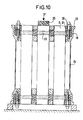
- filter elements of this type are then assembled in a steel casing 24, by means of a compressed gasket assembly in silicone rubber with Shore A hardness of 50, as shown in FIG. 10, where all the filter elements have not shown for clarity.
- the seal 19 is compressed using bolts 20 by clamping between two steel plates 21, 22 perpendicular to the axis of the filter elements, optionally provided with rough areas 23 at the seal.
- a vacuum is made in the external envelope 24, then it is filled with a solution of caustic soda at 5% by weight and it is left to flow for 4 hours to be sure that the soda has penetrated wherever it could.
- the filter element shown in FIG. 2 is a tube with an inside diameter of 7 mm and an outside diameter of 10 mm, with an average pore diameter of 15 microns, made of pure alumina, obtained by extrusion. It does not have a finer porosity layer on its inner surface, and therefore sealing of its ends is not necessary.
- Seven of these tubes are mounted in a metal envelope by means of a compressed elastic seal applied. over a length of 30 mm from each end of the tubes, and therefore exactly covering the rough surface.
- Example 2 The procedure is as in Example 1, but replacing the enamel with a layer 10A of epoxy resin sold under the brand "Araldite”, which is used both to impregnate the end of element 2 (fig.3) and sticking the alumina grains 11 to the outer surface.
- Example 2 On the filter elements of Example 2, a compound is deposited pasty ceramic including (by weight)
- the same filter element is used as that of Example 2.
- Au during the manufacture of the tube constituting this element, just after its extrusion, when it is still in the form of plastic paste, it is deformed so as to create at each end a circumferential groove with a width of 8 mm and a depth of 0, 5 mm, at a distance of 15 mm from the end.
- a bonded silicone rubber seal is used.
- a prior treatment of the active parts of the filter element and of the envelope is carried out using a primer such as the product 1200 sold by the company Dow Corming, and a molding in place of the seal.
- the macroporous block pierced with longitudinal channels of Example 1 is used, impregnating it with enamel for 30 mm at each end.
- a rough area (13, fig. 8) is formed on the enamelled outer surface by sanding over a width of 12 mm, in the middle of the enameled area (using a mask so as not to sand the part of the enameled area which must remain smooth).
- Example 4 The procedure is as in Example 4, but forming the beads as follows. Alumina powder is formed by schooping (projection of particles melted in a flame) three beads of width 3 mm and thickness 0.4 mm, using masks to limit the projection to the area where it is to be formed the beads.
- the filter element is a stainless steel tube (2, fig. 9) with an inside diameter of 15 mm and an outside diameter of 30 mm, obtained by sintering a stainless steel powder with an average particle diameter of 30 microns. Its external surface 14 is covered over a length of 30 mm from each end of a mixture consisting of 4 parts by weight of a copper-silver brazing composition, and of a part of small stainless steel balls of average diameter 100 microns, coated in an organic glue.
- the element is subjected to a heat treatment at 700 ° C., during which the solder melts.
- the small beads bonded by the solder form a rough layer on the external surface of the element, while the excess of solder is absorbed by capillarity by the porosity of the element.
- protuberances 16 are arranged on the zone of the external surface of the end of the element facing the seal 9. They are obtained as follows. Before or after the sintering of the element, a ribbon of ceramic paste is deposited on its end, and firing is carried out to ensure the sintering of this ribbon and its connection with the surface of the element. It is also possible to use grains of ceramic material bonded together and with the surface of the element by an enamel, or by a polymerizable resin, loaded or not with grains of mineral material. These protuberances can finally be produced by local deformation of the material of the filter element during its shaping.
- FIG. 7 represents depressions 17 formed in the external surface of the end of the filter element. They are obtained either by local deformation of the material of the element during its shaping, or by machining after this shaping.
- the device according to the invention allows first, as shown in the tests described in the examples, very significantly increase the sliding resistance of the filter element relative to the seal.
- the element does not move when tightening the compressed joint.
- compressed seals on smooth surfaces do not hold the filter elements sufficiently long, which shift longitudinally under the influence of pressure differences, pressure increases and decreases, pressure surges as well as differential thermal expansions.
- the danger of longitudinal offset of the joint in service is even greater in the case of a glued joint.
- the invention also makes it possible to use seals made of a more flexible material, since there is no need to tighten the seal so tightly around the filter element. These more flexible seals better withstand the deformations caused by the differential expansions between the generally metallic casing and the generally ceramic filter elements.
Abstract
Dispositif d'assemblage d'au moins un élément filtrant tubulaire (2) dans une enveloppe (5) entourant cet élément, comprenant un joint (9) en matériau élastomère ou polymère disposé à au moins l'une de extrémités de l'élément filtrant et de l'enveloppe entre la surface externe d'élément filtrant et la surface interne de l'enveloppe. La surface externe de l'élément filtrant est munie sur au moins une partie de sa longueur en regard du joint de rugosités (11) ou de reliefs ou creux de nombre et de dimensions suffisants pour éviter un glissement de l'élément filtrant le long du joint. Applications en microfiltration, ultrafiltration et osmose inverse.Device for assembling at least one tubular filter element (2) in an envelope (5) surrounding this element, comprising a seal (9) made of elastomeric or polymeric material disposed at at least one of the ends of the filter element and the envelope between the outer surface of the filter element and the inner surface of the envelope. The external surface of the filter element is provided over at least part of its length opposite the joint with roughnesses (11) or reliefs or hollows of sufficient number and dimensions to prevent sliding of the filter element along the attached. Microfiltration, ultrafiltration and reverse osmosis applications.
Description
La présente invention concerne un dispositif d'assemblage d'au moins un élément de séparation tubulaire dans une enveloppe entourant cet élément, comprenant un joint en matériau élastomère ou polymère disposé à au moins l'une des extrémités de l'élément filtrant et de l'enveloppe entre la surface externe de l'élément filtrant et la surface interne de l'enveloppe. Elle s'applique particulièrement, mais non exclusivement, aux dispositifs de filtration par faisceaux de tubes poreux, ou à ceux de séparation par membrane pour la filtration, l'ultrafiltration ou l'osmose inverse, qui ont fait l'objet l'objet de la demande de brevet français-n" 8403368 du 5 mars 1984 de la demanderesse, comprenant un bloc macroporeux en céramique, verre ou métal frittés, ou en carbone, percé de canaux longitudinaux parallèles.The present invention relates to a device for assembling at least one tubular separation element in an envelope surrounding this element, comprising a seal made of elastomeric or polymeric material disposed at at least one of the ends of the filter element and of the envelope between the external surface of the filter element and the internal surface of the envelope. It applies particularly, but not exclusively, to filtration devices by bundles of porous tubes, or to those for membrane separation for filtration, ultrafiltration or reverse osmosis, which have been the subject of French patent application No. 8403368 of March 5, 1984 of the applicant, comprising a macroporous block of ceramic, glass or sintered metal, or carbon, pierced with parallel longitudinal channels.
Le montage de plusieurs éléments de séparation par membrane de ce genre dans une enveloppe métallique se fait au moyen de joints en matière plastique ou élastique qui ont plusieurs fonctions :
- - assurer la séparation entre la cavité contenant le liquide à filtrer et celle contenant le filtrat,
- - maintenir en place les éléments filtrants en présence d'une forte différence de pression (pouvant atteindre plusieurs dizaines de bars) entre ces cavités,
- - résister aux différences de dilatation thermique entre l'enveloppe (métallique ou en matière plastique renforcée de fibres de verre) et l'élément de séparation, généralement en matière céramique, qui peuvent atteindre jusqu'à 0,5 ou 1 mm.
- - ensure the separation between the cavity containing the liquid to be filtered and that containing the filtrate,
- - keep the filter elements in place in the presence of a large pressure difference (up to several tens of bars) between these cavities,
- - resist differences in thermal expansion between the envelope (metallic or plastic reinforced with glass fibers) and the separating element, generally made of ceramic material, which can reach up to 0.5 or 1 mm.
Or la surface latérale extérieure de l'élément de séparation tubulaire est généralement lisse, soit qu'elle soit recouverte d'un émail ou d'une résine pour empêcher la communication à travers la porosité grossière du support des membranes entre les cavités du liquide à filtrer et du filtrat, soit que l'élément ait été fabriqué par extrusion. La résistance de l'élément filtrant au glissement par rapport au joint est relativement faible, d'autant plus que l'élément de séparation est souvent en présence de liquides qui jouent le rôle de lubrifiant de ce glissement, par exemple des liquides visqueux ou une solution de soude caustique, souvent utilisée pour le lavage de la surface de la membrane de séparation après filtration de produits gras, qui réagit sur ceux-ci en donnant des savons.However, the external lateral surface of the tubular separating element is generally smooth, either that it is covered with an enamel or a resin to prevent communication through the coarse porosity of the support of the membranes between the cavities of the liquid to be filter and filtrate, or that the element was manufactured by extrusion. The resistance of the filter element to sliding relative to the seal is relatively low, especially since the separating element is often in the presence of liquids which play the role of lubricant of this sliding, for example viscous liquids or a soda solution caustic, often used for washing the surface of the separation membrane after filtration of fatty products, which reacts on them by giving soaps.
On a jusqu'ici recouru pour empêcher le glissement
- - soit à une forte compression du joint, qui risque d'entraîner son déchirement,
- - soit à un collage du joint sur l'élément. Mais il est difficile de trouver des colles qui résistent aux contraintes de cisaillement, aux corrosions chimiques par les fluides filtrés ou ceux de nettoyage, aux températures souvent élevées et au vieillissement en service,
- - soit à la mise en place de butées mécaniques, qui sont coûteuses et doivent souvent être de forme compliquée, qui entraîne l'existence de cavités ou fentes difficiles à nettoyer et susceptibles d'abriter des proliférations microbiennes.
- - either a strong compression of the joint, which risks causing it to tear,
- - either to a bonding of the seal on the element. But it is difficult to find adhesives which resist shear stresses, chemical corrosion by filtered or cleaning fluids, often high temperatures and aging in service,
- - Either the installation of mechanical stops, which are expensive and often have to be of complicated shape, which causes the existence of cavities or slots difficult to clean and capable of harboring microbial proliferation.
La présente invention a pour but de remédier à ces difficultés, et de procurer un assemblage de l'élément filtrant et de l'enveloppe qui l'entoure résistant bien au glissement, aux corrosions chimiques et aux températures élevées, tout en étant d'une structure simple et de fabrication peu coûteuse.The object of the present invention is to remedy these difficulties, and to provide an assembly of the filter element and of the envelope which surrounds it, resistant well to sliding, to chemical corrosions and to high temperatures, while being of a simple structure and inexpensive to manufacture.
Le dispositif d'assemblage selon l'invention est caractérisé en ce que la surface externe de l'élément filtrant est munie sur au moins une partie de sa longueur en regard du joint de rugosités ou de reliefs ou creux de nombre et de dimensions suffisants pour éviter un glissement de l'élément filtrant le long du joint.The assembly device according to the invention is characterized in that the external surface of the filter element is provided over at least part of its length opposite the joint with roughness or reliefs or hollows of sufficient number and dimensions to avoid sliding of the filter element along the seal.
Il répond en outre de préférence à l'un ou l'autre des variantes de réalisation ci-après :
- - l'extrémité de l'élément est revêtue d'un émail ou verre, et les rugosités sont formées par des grains grossiers dans l'émail ou verre.
- - Les rugosités sont formées par des grains grossiers dispersés dans un adhésif organique déposé sur l'extrémité de l'élément filtrant.
- - L'extrémité de l'élément est revêtue d'une résine synthétique, et les rugosités sont formées par des grains grossiers incrustés dans la résine synthétique.
- - Les rugosités sont formées par des grains grossiers projetés à l'état au moins partiellement fondu, ou bien déposés, puis brasés sur le pour tour de l'élément filtrant.
- - Les rugosités sont formées par abrasion de l'extrémité de l'élément filtrant.
- - Les reliefs sont constitués par des surépaisseurs locales ou circonférentielles, formées par un ou plusieurs rubans de matière enroulés autour de l'extrémité de l'élément filtrant.
- - Les creux sont circonférentiels, et résultent de déformations locales de l'extrémité de l'élément filtrant lors de sa mise en forme avant ouisson ou frittage, ou d'un usinage de l'extrémité de l'élément déjà ouit ou fritté.
- - The end of the element is coated with an enamel or glass, and the roughness is formed by coarse grains in the enamel or glass.
- - The roughness is formed by coarse grains dispersed in an organic adhesive deposited on the end of the filter element.
- - The end of the element is coated with a synthetic resin, and the roughness is formed by coarse grains embedded in the synthetic resin.
- - The roughnesses are formed by coarse grains projected in the at least partially molten state, or else deposited, then brazed on the round the filter element.
- - The roughness is formed by abrasion of the end of the filter element.
- - The reliefs are constituted by local or circumferential thicknesses, formed by one or more ribbons of material wound around the end of the filter element.
- - The hollows are circumferential, and result from local deformations of the end of the filter element during its shaping before leveling or sintering, or from a machining of the end of the element already seated or sintered.
La surface rugeuse ou munie de reliefs ou creux peut couvrir toute la surface de contact entre l'élément de séparation et le joint. Dans ce cas, on obtient une résistance au glissement très élevée. Mais il y a des risques de fuites si le joint n'épouse pas très exactement les variations plus ou moins irrégulières de niveau de la surface externe de l'élément.The rough surface or provided with reliefs or hollows can cover the entire contact surface between the separating element and the joint. In this case, a very high sliding resistance is obtained. However, there is a risk of leaks if the seal does not very exactly match the more or less irregular variations in level of the external surface of the element.
Elle peut aussi ne couvrir qu'une partie de la surface de contact entre l'élément de séparation et le joint, et notamment être comprise entre deux surfaces non modifiées, et donc relativement lisses. Dans ce cas, l'étanchéité est mieux assurée, mais la résistance au glissement n'est pas aussi élevée que dans le premier cas.It can also cover only part of the contact surface between the separating element and the joint, and in particular be between two unmodified surfaces, and therefore relatively smooth. In this case, the seal is better ensured, but the slip resistance is not as high as in the first case.
Il est décrit ci-après, à titre d'exemples et en référence aux figures du dessin annexé, des variantes de réalisation de l'invention.
- La figure 1 représente en coupe partielle l'extrémité d'un élément de filtration macroporeux percé de canaux auquel s'applique l'invention.
- La figure 2 représente en coupe partielle à échelle agrandie une surface de contact entre l'élément de filtration et le joint d'étanchéité. L'extrémité de l'élément n'est pas imprégnée par un émail d'étanchéification. Les grains grossiers de matière céramique sont disposés dans un émail déposé sur l'extrémité de l'élément.
- La figure 3 représente en coupe partielle à échelle agrandie une surface de contact entre l'élément de filtration et le joint assurant l'étanchéité entre cet élément et l'enveloppe métallique qui l'entoure et forme la paroi des chambres de recueil du filtrat et du liquide à filtrer. L'extrémité de l'élément est revêtue d'un émail d'étanchéifi- oation, puis d'un autre émail dans lequel ont été incorporés des grains grossiers de matière céramique.
- La figure 4 représente en coupe partielle à échelle agrandie une aurfaoe de oontaot analogue, mais dans laquelle les grains grossiers de céramique sont liés par frittage à l'élément filtrant.
- La figure 5 représente en coupe partielle à échelle agrandie une surface de contact analogue, dans laquelle des surépaisseurs circulaires locales ont été formées sur la surface de l'élément filtrant à l'aide d'un ruban de matière céramique ou résine synthétique enroulé autour de l'extrémité de l'élément.
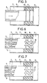
- La figure 6 représente en coupe partielle à échelle agrandie une surface de contact analogue, dans laquelle des surépaisseurs locales ponctuelles ont été formées par dépôt sur la surface de grains de matière par projection à l'état fondu ou partiellement fondu.
- La figure 7 représente en coupe partielle à échelle agrandie une surface de contact analogue, dans laquelle des rainures ou creux ont été formés sur la surface extérieure de l'extrémité de l'élément.
- La figure 8 représente en coupe partielle une extrémité de l'élément de filtration dont seule une partie de la surface en regard du joint a été munie de rugosités.
- La figure 9 représente en coupe partielle une extrémité de l'élément de filtration, dont la totalité de la surface en regard du joint a été munie de rugosités.
- La figure 10 représente en coupe un élément de filtration avec ses joints d'étanchéité aux deux extrémités et des écrous de serrage de ces joints entre des plaques d'acier.
- Figure 1 shows in partial section the end of a macroporous filtration element pierced with channels to which the invention applies.
- Figure 2 shows in partial section on an enlarged scale a contact surface between the filter element and the seal. The end of the element is not impregnated with a sealing enamel. The coarse grains of ceramic material are placed in an enamel deposited on the end of the element.
- FIG. 3 shows in partial section on an enlarged scale a contact surface between the filter element and the seal ensuring the seal between this element and the metal envelope which surrounds it and forms the wall of the filtrate collection chambers and liquid to be filtered. The end of the element is coated with a sealing enamel, then with another enamel in which grains have been incorporated. coarse ceramic material.
- FIG. 4 represents in partial section on an enlarged scale an aurfaoe of similar oontaot, but in which the coarse grains of ceramic are bonded by sintering to the filter element.
- FIG. 5 shows in partial section on an enlarged scale a similar contact surface, in which local circular extra thicknesses have been formed on the surface of the filtering element using a ribbon of ceramic material or synthetic resin wound around the end of the element.
- FIG. 6 represents in partial section on an enlarged scale a similar contact surface, in which point local extra thicknesses have been formed by deposition on the surface of grains of material by projection in the molten or partially molten state.
- FIG. 7 shows in partial section on an enlarged scale an analogous contact surface, in which grooves or hollows have been formed on the external surface of the end of the element.
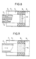
- Figure 8 shows in partial section one end of the filter element of which only a part of the surface facing the seal has been provided with roughness.
- Figure 9 shows in partial section one end of the filter element, the entire surface facing the seal has been provided with roughness.
- Figure 10 shows in section a filter element with its seals at both ends and nuts for tightening these seals between steel plates.
On utilise un bloc macroporeux muni de canaux longitudinaux pourvus d'une membrane de filtration formant élément de filtration tangentielle, dont l'extrémité est représentée en figure 3. Cet élément filtrant 1 comporte une surface extérieure 2, des canaux 3 où circule le fluide à filtrer, munis de membranes de filtration 4, de porosité notablement plus faible que celle du bloc. Il est entouré par une enveloppe métallique 5, qui définit à son extrémité droite une chambre 6 de recueil de l'excès de fluide à filtrer, et autour du bloc macroporeux une chambre 7 de recueil d'un filtrat.,Une tubulure 8 permet l'évacuation du filtrat. Les chambres 6 et 7 sont isolées l'une de l'autre par un joint 9 en matériau élastomère. A macroporous block is used provided with longitudinal channels provided with a filtration membrane forming a tangential filtration element, the end of which is shown in FIG. 3. This filter element 1 has an
L'extrémité de l'élément filtrant est étanchéifiée sur une longueur de 30 mm par un émail de composition pondérale

On broie l'émail en une poudre jusqu'à obtenir un diamètre moyen de particules d'environ 1 micron. On prépare alors une barbotine de la composition pondérale suivante

On obtient ainsi une barbotine très bien défloculée. On verse cette barbotine dans une cuve à agitation par ultra-sons. On plonge chacune des extrémités de l'élément filtrant dans le liquide sur une profondeur de 25 mm. On l'y maintient pendant 30 minutes sous agitation par les ultra-sons. A la fin de cette période, la barbotine a pénétré dans la porosité de l'extrémité de l'élément sur une hauteur de 30 mm (les 25 mm immergés plus 5 mm de montée par capillarité). On retire l'élément du bain de barbotine, on sèche la barbotine absorbée.A very well deflocculated slip is thus obtained. This slip is poured into an ultrasonic shaker tank. Each end of the filter element is immersed in the liquid to a depth of 25 mm. It is kept there for 30 minutes with agitation by ultrasound. At the end of this period, the slip entered the porosity of the end of the element over a height of 30 mm (the 25 mm submerged plus 5 mm rise by capillarity). The element is removed from the slip bath, the absorbed slip is dried.
Puis on prépare une barbotine de la composition pondérale suivante :

Cette barbotine est très visqueuse. On la dépose au pinceau sur une largeur de 8 mm, en une bande 10A qui fait le tour de l'élément filtrant macroporeux, en laissant une plage non recouverte de largeur 9 mm entre la bande et l'extrémité de l'élément. Les grains d'alumine 11 de cette seconde barbotine sont trop gros pour pénétrer dans les pores de l'élément filtrant.This slip is very viscous. It is deposited with a brush over a width of 8 mm, in a strip 10A which goes around the macroporous filter element, leaving an uncoated area of
On soumet l'ensemble des deux dépôts à une cuisson en atmosphère oxydante à 13000C pour fondre l'émail. On réalise cette opération sur les deux extrémités de l'élément.All of the two deposits are subjected to firing in an oxidizing atmosphere at 1300 ° C. to melt the enamel. This operation is carried out on both ends of the element.
On obtient ainsi des extrémités d'élément filtrant étanchéifiées sur une longueur de 30 mm et portant au milieu de la zone étanchéifiée une bande rugueuse de largeur 9 mmThe ends of the sealed filter element are thus obtained over a length of 30 mm and carrying in the middle of the sealed zone a rough band of
On assemble ensuite 7 éléments filtrants de ce type dans une enveloppe 24 en acier, au moyen d'un montage à joint comprimé en caoutchouc silicone de dureté Shore A de 50, comme représenté sur la figure 10, où tous les éléments filtrants n'ont pas été représentés pour plus de clarté. Le joint 19 est comprimé à l'aide de boulons 20 par serrage entre deux plaques d'acier 21, 22 perpendiculaires à l'axe des éléments filtrants, munis éventuellement des zones rugueuses 23 au niveau du joint. On fait le vide dans l'enveloppe externe 24, puis on la remplit d'une solution de soude caustique à 5% en poids et on la laisse écouler pendant 4 heures pour être sûr que la soude a pénétré partout où elle le pouvait.7 filter elements of this type are then assembled in a
Les plaques métalliques 21, 22 supports du joint étant immobilisées, on applique sur l'un des éléments filtrants par l'intermédiaire d'une cale 25 une force F croissante parallèle à l'axe de cet élément jusqu'à obtenir son glissement par rapport au joint. La force nécessaire pour obtenir le glissement est de :
- - 300 Newtons en l'absence de zone rugueuse.
- - 1700 Newtons avec la zone rugueuse obtenue comme indiquée ci-dessus.
- - 300 Newtons in the absence of rough area.
- - 1700 Newtons with the rough zone obtained as indicated above.
L'élément filtrant représenté en figure 2 est un tube de diamètres intérieur 7 mm et extérieur 10 mm, de diamètre moyen de pores 15 microns, en alumine pure, obtenu par extrusion. Il ne comporte pas sur sa surface intérieure de couche à porosité plus fine, et de ce fait une étanchéification de ses extrémités n'est pas nécessaire.The filter element shown in FIG. 2 is a tube with an inside diameter of 7 mm and an outside diameter of 10 mm, with an average pore diameter of 15 microns, made of pure alumina, obtained by extrusion. It does not have a finer porosity layer on its inner surface, and therefore sealing of its ends is not necessary.
On recouvre sa surface latérale extérieure sur une longueur de 30 mm à partir des extrémités au moyen de la seconde barbotine utilisée dans l'exemple 1, et on effectue une cuisson pour assurer la fusion de l'émail. On obtient ainsi à chaque extrémité une bande rugueuse 10 de largeur 30 mm, à particules en relief 11.Its outer lateral surface is covered over a length of 30 mm from the ends by means of the second slip used in Example 1, and firing is carried out to ensure the melting of the enamel. A
0n monte sept de ces tubes dans une enveloppe métallique au moyen d'un joint élastique comprimé appliqué. sur une longueur de 30 mm à partir de chaque extrémité des tubes, et recouvrant donc exactement la surface rugueuse.Seven of these tubes are mounted in a metal envelope by means of a compressed elastic seal applied. over a length of 30 mm from each end of the tubes, and therefore exactly covering the rough surface.
On effectue le même essai que dans l'exemple 1, et on mesure les résistances limites au glissement. On obtient
- 150 Newtons en l'absence de surface rugueuse.
- 700 Newtons avec la surface rugueuse (il se produit alors un déchirement du joint).
- 150 Newtons in the absence of a rough surface.
- 700 Newtons with rough surface (there is a tear in the joint).
On opère comme dans l'exemple 1, mais en remplaçant l'émail par une couche 10A de résine époxy commercialisée sous la marque "Araldite", qui sert à la fois à imprégner l'extrémité de l'élément 2 (fig.3) et à coller les grains d'alumine 11 sur la surface extérieure.The procedure is as in Example 1, but replacing the enamel with a layer 10A of epoxy resin sold under the brand "Araldite", which is used both to impregnate the end of element 2 (fig.3) and sticking the alumina grains 11 to the outer surface.
Les valeurs des résistances limites au glissement sont :
- 300 Newtons en l'absence de surface rugueuse.
- 1500 Newtons avec une surface rugueuse.
- 300 Newtons in the absence of a rough surface.
- 1500 Newtons with a rough surface.
Sur les éléments filtrants de l'exemple 2, on dépose une composition céramique pâteuse comprenant (en poids)On the filter elements of Example 2, a compound is deposited pasty ceramic including (by weight)
Alumine de dimension moyenne de grain

de manière à former après frittage sur la surface latérale extérieure de chaque extrémité de l'élément deux bourrelets (12, fig.5) qui font le tour de l'élément, de largeur 4 mm et d'épaisseur 0,8 mm, situés à des distances de 10 mm et 18 mm de l'extrémité de l'élément.Medium grain alumina
so as to form after sintering on the external lateral surface of each end of the element two beads (12, fig. 5) which go around the element, of
L'essai de résistance au glissement donne les résistances limites
- 150 Newtons en l'absence de bourrelet
- 600 Newtons en présence des bourrelets
- 150 Newtons in the absence of a bead
- 600 Newtons in the presence of the beads
On procède comme dans l'exemple 4, sauf en ce qui concerne les bourrelets de matière céramique, qui sont remplacés par des bourrelets de la composition pondérale suivante :

Les forces limites à l'essai de résistance au glissement sont les suivantes :
- 150 Newtons en l'absence de bourrelet
- 650 Newtons en présence des bourrelets
- 150 Newtons in the absence of a bead
- 650 Newtons in the presence of the beads
On utilise le même élément filtrant que celui de l'exemple 2. Au cours de la fabrication du tube constituant cet élément, juste après son extrusion, au moment où il est encore sous forme de pâte plastique, on le déforme de manière à créer à chaque extrémité une rainure circonférentielle de largeur 8 mm, et de profondeur 0,5 mm, à une distance de 15 mm de l'extrémité.The same filter element is used as that of Example 2. Au during the manufacture of the tube constituting this element, just after its extrusion, when it is still in the form of plastic paste, it is deformed so as to create at each end a circumferential groove with a width of 8 mm and a depth of 0, 5 mm, at a distance of 15 mm from the end.
On emploie par contre un joint en caoutchouc silicone collé. Pour améliorer l'adhérence entre les différents matériaux, on effectue un traitement préalable des parties actives de l'élément filtrant et de l'enveloppe à l'aide d'un primaire tel que le produit 1200 commercialisé par la Société Dow Corming, et un moulage en place du joint.On the other hand, a bonded silicone rubber seal is used. To improve the adhesion between the different materials, a prior treatment of the active parts of the filter element and of the envelope is carried out using a primer such as the product 1200 sold by the company Dow Corming, and a molding in place of the seal.
Les valeurs des forces limites à l'apparition du glissement sont :
- 150 Newtons en l'absence de rainure
- 400 Newtons en présence d'une rainure.
- 150 Newtons without groove
- 400 Newtons in the presence of a groove.
On utilise le bloc macroporeux percé de canaux longitudinaux de l'exemple 1, en l'imprégnant à l'émail sur 30 mm à chaque extrémité.The macroporous block pierced with longitudinal channels of Example 1 is used, impregnating it with enamel for 30 mm at each end.
On forme sur la surface extérieure émaillée une zone rugueuse (13, fig.8) par sablage sur une largeur de 12 mm, au milieu de la zone émaillée (en utilisant un masque pour ne pas sabler la partie de la zone émaillée qui doit rester lisse).A rough area (13, fig. 8) is formed on the enamelled outer surface by sanding over a width of 12 mm, in the middle of the enameled area (using a mask so as not to sand the part of the enameled area which must remain smooth).
Les valeurs limites des forces à l'amorce de glissement sont :
- 300 Newtons en l'absence de zone rugueuse
- 500 Newtons en présence d'une zone rugueuse.
- 300 Newtons in the absence of rough areas
- 500 Newtons in the presence of a rough area.
On opère comme dans l'exemple 4, mais en formant les bourrelets comme suit. On forme par schoopage de poudre d'alumine (projection de particules fondues dans une flamme) trois bourrelets de largeur 3 mm et d'épaisseur 0,4 mm, en utilisant des masques pour limiter la projection à la zone où l'on doit former les bourrelets.The procedure is as in Example 4, but forming the beads as follows. Alumina powder is formed by schooping (projection of particles melted in a flame) three beads of
Les valeurs limites des forces à l'amorce de glissement sont les suivantes :
- 150 Newtons en l'absence de bourrelet
- 650 Newtons en présence des bourrelets.
- 150 Newtons in the absence of a bead
- 650 Newtons in the presence of the beads.
L'élément filtrant est un tube en acier inoxydable (2,fig.9) de diamètres intérieur 15 mm et extérieur 30 mm, obtenu par frittage d'une poudre d'acier inoxydable de diamètre moyen de particules 30 microns. On recouvre sa surface externe 14 sur une longueur de 30 mm à partir de chaque extrémité d'un mélange constitué de 4 parties en poids d'une composition de brasure cuivre-argent, et d'une partie de petites billes d'acier inoxydable de diamètre moyen 100 microns, enrobées dans une colle organique.The filter element is a stainless steel tube (2, fig. 9) with an inside diameter of 15 mm and an outside diameter of 30 mm, obtained by sintering a stainless steel powder with an average particle diameter of 30 microns. Its
On soumet 'l'élément à un traitement thermique à 700°C, au cours duquel la brasure fond. Les petites billes liées par la brasure forment une couche rugueuse sur la surface externe de l'élément, tandis que l'excès de brasure est absorbé par capillarité par la porosité de l'élément.The element is subjected to a heat treatment at 700 ° C., during which the solder melts. The small beads bonded by the solder form a rough layer on the external surface of the element, while the excess of solder is absorbed by capillarity by the porosity of the element.
L'essai de résistance au glissement donne les résultats suivants :
- 250 Newtons en l'absence de zone rugueuse
- 1200 Newtons en présence de zone rugueuse.
- 250 Newtons in the absence of a rough area
- 1200 Newtons in the presence of rough area.
Dans l'élément de filtration représenté en figure 4, des grains grossiers de céramique 15 ont été disposés sur la surface externe de l'élément filtrant à l'aide d'une colle organique. On effectue ensuite un frittage, au cours duquel la colle organique est brûlée et les grains de céramique sont liés à la surface externe de l'élément.In the filter element shown in FIG. 4, coarse grains of ceramic 15 have been placed on the external surface of the filter element using an organic adhesive. Sintering is then carried out, during which the organic glue is burnt and the ceramic grains are bonded to the external surface of the element.
Dans l'élément de filtration représenté en figure 6, des protubérances 16, par exemple en matière céramique, sont disposées sur la zone de la surface externe de l'extrémité de l'élément en regard du joint 9. Elles sont obtenues comme suit. Avant ou après le frittage de l'élément, on dépose sur son extrémité un ruban de pâte céramique, et on effectue une cuisson pour assurer le frittage de ce ruban et sa liaison avec la surface de l'élément. On peut aussi utiliser des grains de matière céramique liés entre eux et avec la surface de l'élément par un émail, ou par une résine polymérisable, chargée ou non de grains de matière minérale. Ces protubérances peuvent enfin être réalisées par déformation locale de la matière de l'élément filtrant lors de sa mise en forme.In the filtration element shown in FIG. 6,
La figure 7 représente des dépressions 17 formées dans la surface externe de l'extrémité de l'élément filtrant. Elles sont obtenues soit par déformation locale de la matière de l'élément lors de sa mise en forme, soit par usinage après cette mise en forme.FIG. 7 represents
- Le dispositif selon l'invention permet en premier lieu, comme l'on montré les essais décrits dans les exemples, d'augmenter très notablement la résistance au glissement de l'élément filtrant par rapport au joint. L'élément ne bouge pas lors du serrage du joint comprimé. En service, les joints comprimés sur les surfaces lisses ne maintiennent pas suffisamment à la longue les éléments filtrants, qui se décalent longitudinalement sous l'influence des différences de pression, des montées et descentes en pression, des coups de bélier éventuels, ainsi que des dilatations thermiques différentielles. Le danger de décalage longitudinal du joint en service est encore plus important dans le cas d'un joint collé. - The device according to the invention allows first, as shown in the tests described in the examples, very significantly increase the sliding resistance of the filter element relative to the seal. The element does not move when tightening the compressed joint. In service, compressed seals on smooth surfaces do not hold the filter elements sufficiently long, which shift longitudinally under the influence of pressure differences, pressure increases and decreases, pressure surges as well as differential thermal expansions. The danger of longitudinal offset of the joint in service is even greater in the case of a glued joint.
On évite ainsi d'avoir à recouvrir pour éviter ce décalage à des butées mécaniques, notamment par un usinage coûteux des plaques qui compriment le joint.This avoids having to cover to avoid this offset to mechanical stops, in particular by expensive machining of the plates which compress the seal.
L'invention permet aussi d'utiliser des joints en une matière plus flexible, puisque l'on n'a pas besoin de serrer aussi fortement le joint autour de l'élément filtrant. Ces joints plus flexibles supportent mieux les déformations engendrées par les dilatations différentielles entre l'enveloppe généralement métallique et les éléments filtrants généralement en céramique.The invention also makes it possible to use seals made of a more flexible material, since there is no need to tighten the seal so tightly around the filter element. These more flexible seals better withstand the deformations caused by the differential expansions between the generally metallic casing and the generally ceramic filter elements.
Claims (6)
Applications Claiming Priority (2)
| Application Number | Priority Date | Filing Date | Title |
|---|---|---|---|
| FR8409687 | 1984-06-20 | ||
| FR8409687A FR2566282B1 (en) | 1984-06-20 | 1984-06-20 | DEVICE FOR ASSEMBLING A TUBULAR FILTERING ELEMENT IN AN ENCLOSURE |
Publications (2)
| Publication Number | Publication Date |
|---|---|
| EP0170025A1 true EP0170025A1 (en) | 1986-02-05 |
| EP0170025B1 EP0170025B1 (en) | 1989-01-25 |
Family
ID=9305243
Family Applications (1)
| Application Number | Title | Priority Date | Filing Date |
|---|---|---|---|
| EP85107504A Expired EP0170025B1 (en) | 1984-06-20 | 1985-06-18 | Apparatus for fitting a tubular filter element in a shell |
Country Status (6)
| Country | Link |
|---|---|
| US (1) | US4640774A (en) |
| EP (1) | EP0170025B1 (en) |
| JP (1) | JPH07172B2 (en) |
| CA (1) | CA1239096A (en) |
| DE (1) | DE3567808D1 (en) |
| FR (1) | FR2566282B1 (en) |
Cited By (3)
| Publication number | Priority date | Publication date | Assignee | Title |
|---|---|---|---|---|
| FR2616812A1 (en) * | 1987-06-18 | 1988-12-23 | Lyonnaise Eaux | Process for the manufacture of an organic porous material and especially of an organic semipermeable membrane, die for making use of this process, membranes produced and filter modules containing these membranes |
| EP0310632A1 (en) * | 1987-04-02 | 1989-04-12 | Robert L Goldsmith | Cross-flow filtration device and method of making. |
| EP0783004A1 (en) | 1996-01-08 | 1997-07-09 | Basf Aktiengesellschaft | Process for the production of insoluble-in-water polymers |
Families Citing this family (22)
| Publication number | Priority date | Publication date | Assignee | Title |
|---|---|---|---|---|
| US5133746A (en) * | 1985-12-09 | 1992-07-28 | Allergan, Inc. | Intraocular lens with roughened fixation member |
| FR2607880B1 (en) * | 1986-12-03 | 1989-02-03 | Ceramiques Tech Soc D | METHOD FOR ASSEMBLING A MODULE OF SEPARATING ELEMENTS WITH CERAMIC SUPPORT AND MODULE OBTAINED BY THIS METHOD |
| FR2634668B1 (en) * | 1988-07-29 | 1990-09-14 | Ceramiques Tech Soc D | MODULE FOR RIGID CYLINDRICAL ELEMENTS WITH SEPARATION, FILTRATION OR CATALYTIC MEMBRANE |
| FR2658431B1 (en) * | 1990-02-16 | 1992-04-30 | Ceramiques Tech Soc D | MEMBRANE DEVICE FOR FILTRATION, SEPARATION OR CATALYTIC REACTION. |
| US5104546A (en) * | 1990-07-03 | 1992-04-14 | Aluminum Company Of America | Pyrogens separations by ceramic ultrafiltration |
| FR2665646B1 (en) * | 1990-08-07 | 1993-08-13 | Total France | DEVICE COMPRISING A BEAM OF TUBES MOUNTED IN A CALENDER AND HAVING DIFFERENTIAL EXPANSION THEREWITH. |
| US5242595A (en) * | 1991-04-25 | 1993-09-07 | U.S. Filter/Illinois Water Treatment, Inc. | Bacteria removal by ceramic microfiltration |
| FR2697886B1 (en) * | 1992-11-12 | 1994-12-30 | Tech Sep | Elastomer seal for filtration module. |
| GB9504908D0 (en) * | 1995-03-10 | 1995-04-26 | Bellhouse Brian John | Filter |
| DE19846041A1 (en) | 1998-10-07 | 2000-04-20 | Membraflow Gmbh & Co Kg Filter | Membrane module |
| JP4517473B2 (en) * | 2000-07-24 | 2010-08-04 | 株式会社デンソー | Waterproof structure for vehicle periphery monitoring device |
| DE10227721B4 (en) * | 2002-06-21 | 2008-03-13 | Hermsdorfer Institut Für Technische Keramik E.V. | Process for producing a bundle of ceramic capillaries for a separation module |
| US7441665B2 (en) * | 2003-10-01 | 2008-10-28 | Halosource, Inc. | Water purification cartridge |
| US20120285882A1 (en) * | 2011-05-10 | 2012-11-15 | Teoh May May | Membrane and method for producing the same |
| DE102013018495B4 (en) * | 2013-11-04 | 2021-05-06 | Vinoval Gmbh | Drinking glass |
| CN109952197A (en) | 2016-09-20 | 2019-06-28 | 阿夸曼布拉尼斯有限责任公司 | Penetrant flows pattern |
| KR102033982B1 (en) | 2016-11-19 | 2019-10-18 | 아쿠아 멤브레인스 엘엘씨 | Interference Patterns For Spiral-Wound Elements |
| WO2018190937A1 (en) | 2017-04-12 | 2018-10-18 | Aqua Membranes Llc | Graded spacers for filtration wound elements |
| EP3612293A4 (en) | 2017-04-20 | 2020-12-30 | Aqua Membranes, Inc. | Non-nesting, non-deforming patterns for spiral-wound elements |
| US11745143B2 (en) | 2017-04-20 | 2023-09-05 | Aqua Membranes, Inc. | Mixing-promoting spacer patterns for spiral-wound elements |
| KR102513191B1 (en) | 2017-10-13 | 2023-03-22 | 아쿠아 멤브레인스 인코포레이티드 | Bridge supports and reduced feed spacers for spiral wound elements |
| JP2023521977A (en) | 2020-04-07 | 2023-05-26 | アクア メンブレインズ,インコーポレイテッド | Independent spacer and method |
Citations (6)
| Publication number | Priority date | Publication date | Assignee | Title |
|---|---|---|---|---|
| FR1178480A (en) * | 1957-05-03 | 1959-05-11 | Commissariat Energie Atomique | Porous tube diffuser |
| FR1227401A (en) * | 1959-03-05 | 1960-08-19 | Batignolles Chatillon | Improvements to tube diffusers |
| FR1280034A (en) * | 1960-11-16 | 1961-12-29 | Commissariat Energie Atomique | Process for treating the ends of sintered metal filter tubes, with a view to their fixing, and filter tubes obtained by this process |
| FR1573289A (en) * | 1968-05-20 | 1969-07-04 | ||
| EP0092839A1 (en) * | 1982-04-28 | 1983-11-02 | CERAVER Société anonyme dite: | Filter element and processes for producing the same |
| FR2536743A1 (en) * | 1982-11-25 | 1984-06-01 | Toshiba Ceramics Co | Process for bonding a ceramic unit with a thermoplastic resin unit, and composite unit obtained by this process. |
Family Cites Families (9)
| Publication number | Priority date | Publication date | Assignee | Title |
|---|---|---|---|---|
| US3237775A (en) * | 1962-11-29 | 1966-03-01 | Millipore Filter Corp | Beaded filter tube filter assembly |
| US3471178A (en) * | 1966-05-18 | 1969-10-07 | Saline Water Conversion Corp | Tube sheet connector having flexible adhesive sealing means |
| US3834545A (en) * | 1973-02-20 | 1974-09-10 | Abcor Inc | Supported tubular membrane |
| NL179546C (en) * | 1973-05-10 | Union Carbide Corp | MODULE FOR USE IN AN ULTRAFILTRATION DEVICE. | |
| DE2437446A1 (en) * | 1974-08-03 | 1976-02-12 | Krupp Gmbh | MEMBRANE FILTRATION SYSTEM |
| JPS53102878A (en) * | 1977-02-21 | 1978-09-07 | Asahi Chem Ind Co Ltd | Constructure with built-in hollow fiber |
| NL172827C (en) * | 1978-04-18 | 1983-11-01 | Wafilin Bv | MEMBRANE FILTRATION UNIT WITH SEALING COVER SUITABLE FOR THIS. |
| JPS6067115U (en) * | 1983-10-17 | 1985-05-13 | 四季ロール株式会社 | filter |
| FR2560526B1 (en) * | 1984-03-05 | 1989-10-06 | Ceraver | MEMBRANE SEPARATION DEVICE, AND MANUFACTURING METHODS THEREOF |
-
1984
- 1984-06-20 FR FR8409687A patent/FR2566282B1/en not_active Expired
-
1985
- 1985-06-17 CA CA000484173A patent/CA1239096A/en not_active Expired
- 1985-06-18 JP JP60132867A patent/JPH07172B2/en not_active Expired - Lifetime
- 1985-06-18 EP EP85107504A patent/EP0170025B1/en not_active Expired
- 1985-06-18 DE DE8585107504T patent/DE3567808D1/en not_active Expired
- 1985-06-19 US US06/748,581 patent/US4640774A/en not_active Expired - Fee Related
Patent Citations (6)
| Publication number | Priority date | Publication date | Assignee | Title |
|---|---|---|---|---|
| FR1178480A (en) * | 1957-05-03 | 1959-05-11 | Commissariat Energie Atomique | Porous tube diffuser |
| FR1227401A (en) * | 1959-03-05 | 1960-08-19 | Batignolles Chatillon | Improvements to tube diffusers |
| FR1280034A (en) * | 1960-11-16 | 1961-12-29 | Commissariat Energie Atomique | Process for treating the ends of sintered metal filter tubes, with a view to their fixing, and filter tubes obtained by this process |
| FR1573289A (en) * | 1968-05-20 | 1969-07-04 | ||
| EP0092839A1 (en) * | 1982-04-28 | 1983-11-02 | CERAVER Société anonyme dite: | Filter element and processes for producing the same |
| FR2536743A1 (en) * | 1982-11-25 | 1984-06-01 | Toshiba Ceramics Co | Process for bonding a ceramic unit with a thermoplastic resin unit, and composite unit obtained by this process. |
Cited By (4)
| Publication number | Priority date | Publication date | Assignee | Title |
|---|---|---|---|---|
| EP0310632A1 (en) * | 1987-04-02 | 1989-04-12 | Robert L Goldsmith | Cross-flow filtration device and method of making. |
| EP0310632A4 (en) * | 1987-04-02 | 1989-09-19 | Robert L Goldsmith | Cross-flow filtration device and method of making. |
| FR2616812A1 (en) * | 1987-06-18 | 1988-12-23 | Lyonnaise Eaux | Process for the manufacture of an organic porous material and especially of an organic semipermeable membrane, die for making use of this process, membranes produced and filter modules containing these membranes |
| EP0783004A1 (en) | 1996-01-08 | 1997-07-09 | Basf Aktiengesellschaft | Process for the production of insoluble-in-water polymers |
Also Published As
| Publication number | Publication date |
|---|---|
| FR2566282B1 (en) | 1989-07-28 |
| DE3567808D1 (en) | 1989-03-02 |
| JPS6111105A (en) | 1986-01-18 |
| CA1239096A (en) | 1988-07-12 |
| EP0170025B1 (en) | 1989-01-25 |
| FR2566282A1 (en) | 1985-12-27 |
| US4640774A (en) | 1987-02-03 |
| JPH07172B2 (en) | 1995-01-11 |
Similar Documents
| Publication | Publication Date | Title |
|---|---|---|
| EP0170025B1 (en) | Apparatus for fitting a tubular filter element in a shell | |
| CA1298069C (en) | Separating device comprised of modular components assembled in ceramic base plates | |
| CA2108698C (en) | Gas or liquid filtration, separation purification or catalytic transformation module | |
| EP0385089B1 (en) | Method for the installation in a module of a rigid element for membrane separation, filtration or catalytic conversion | |
| FR2717880A1 (en) | Joint containing springs in composite material. | |
| EP0092839B1 (en) | Filter element and processes for producing the same | |
| WO1997037166A1 (en) | Line pipe with a double heat-insulating casing | |
| WO1999032208A1 (en) | Method for sealing and/or joining an end of a ceramic filter | |
| EP0154295B1 (en) | Membrane separation apparatus and methods for making the same | |
| EP0418138A1 (en) | Suspended web for the thermal insulation of cryogenic fuels | |
| EP1963726B1 (en) | External protection for expandable tubular threaded joints | |
| FR2690632A1 (en) | Filter intended to filter an aggressive fluid. | |
| FR2483840A1 (en) | PROCESS FOR COATING POLYTETRAFLUORETHYLENE INTERNAL WALLS OF A METALLIC HOLLOW BODY | |
| WO1998034061A1 (en) | Thermal insulation sheath, in particular for constructing underwater pipelines conveying oil products | |
| FR2497331A1 (en) | CROSSING (OR PERMEATION) DEVICE WITH CUT-SHAPED JOINT | |
| CA2100801A1 (en) | Membrane device for filtration, separation or catalytic reaction | |
| EP0697273A1 (en) | Apparatus and method for applying a plastic top-coat to the surface of a composite article, and coated composite article | |
| CA2123812C (en) | Inorganic filtering unit comprising at least one integrated network for the flow of a liquid medium to be treated and/or of the recovered filtrate | |
| FR2874074A1 (en) | Seal for chamfered ends of tubular construction components, especially pipes, comprises elastomer seal element and thrust ring with angled sides | |
| WO2000030741A1 (en) | Filtration module and method for sealed mounting of module ends | |
| BE1008406A3 (en) | Composite pipe and method for manufacturing. | |
| FR2656824A1 (en) | Method of joining plastic components and components intended to be joined | |
| BE1008710A3 (en) | Means and method for applying a material finishing layer surface plastic pipe; coated pipe. | |
| BE517487A (en) |
Legal Events
| Date | Code | Title | Description |
|---|---|---|---|
| PUAI | Public reference made under article 153(3) epc to a published international application that has entered the european phase |
Free format text: ORIGINAL CODE: 0009012 |
|
| AK | Designated contracting states |
Designated state(s): BE CH DE FR GB IT LI NL SE |
|
| 17P | Request for examination filed |
Effective date: 19860731 |
|
| 17Q | First examination report despatched |
Effective date: 19871016 |
|
| RAP1 | Party data changed (applicant data changed or rights of an application transferred) |
Owner name: CERAVER SOCIETE ANONYME DITE: |
|
| GRAA | (expected) grant |
Free format text: ORIGINAL CODE: 0009210 |
|
| AK | Designated contracting states |
Kind code of ref document: B1 Designated state(s): BE CH DE FR GB IT LI NL SE |
|
| REF | Corresponds to: |
Ref document number: 3567808 Country of ref document: DE Date of ref document: 19890302 |
|
| GBT | Gb: translation of ep patent filed (gb section 77(6)(a)/1977) | ||
| ITF | It: translation for a ep patent filed |
Owner name: JACOBACCI & PERANI S.P.A. |
|
| PLBE | No opposition filed within time limit |
Free format text: ORIGINAL CODE: 0009261 |
|
| STAA | Information on the status of an ep patent application or granted ep patent |
Free format text: STATUS: NO OPPOSITION FILED WITHIN TIME LIMIT |
|
| 26N | No opposition filed | ||
| PGFP | Annual fee paid to national office [announced via postgrant information from national office to epo] |
Ref country code: SE Payment date: 19920522 Year of fee payment: 8 |
|
| PGFP | Annual fee paid to national office [announced via postgrant information from national office to epo] |
Ref country code: CH Payment date: 19920526 Year of fee payment: 8 |
|
| PGFP | Annual fee paid to national office [announced via postgrant information from national office to epo] |
Ref country code: BE Payment date: 19920615 Year of fee payment: 8 |
|
| PG25 | Lapsed in a contracting state [announced via postgrant information from national office to epo] |
Ref country code: SE Effective date: 19930619 |
|
| ITTA | It: last paid annual fee | ||
| PG25 | Lapsed in a contracting state [announced via postgrant information from national office to epo] |
Ref country code: LI Effective date: 19930630 Ref country code: CH Effective date: 19930630 Ref country code: BE Effective date: 19930630 |
|
| BERE | Be: lapsed |
Owner name: CERAVER Effective date: 19930630 |
|
| REG | Reference to a national code |
Ref country code: CH Ref legal event code: PL |
|
| PGFP | Annual fee paid to national office [announced via postgrant information from national office to epo] |
Ref country code: FR Payment date: 19940530 Year of fee payment: 10 |
|
| PGFP | Annual fee paid to national office [announced via postgrant information from national office to epo] |
Ref country code: NL Payment date: 19940630 Year of fee payment: 10 |
|
| EUG | Se: european patent has lapsed |
Ref document number: 85107504.4 Effective date: 19940110 |
|
| PG25 | Lapsed in a contracting state [announced via postgrant information from national office to epo] |
Ref country code: NL Effective date: 19960101 |
|
| PG25 | Lapsed in a contracting state [announced via postgrant information from national office to epo] |
Ref country code: FR Effective date: 19960229 |
|
| NLV4 | Nl: lapsed or anulled due to non-payment of the annual fee |
Effective date: 19960101 |
|
| REG | Reference to a national code |
Ref country code: FR Ref legal event code: ST |
|
| PGFP | Annual fee paid to national office [announced via postgrant information from national office to epo] |
Ref country code: GB Payment date: 19970520 Year of fee payment: 13 |
|
| PGFP | Annual fee paid to national office [announced via postgrant information from national office to epo] |
Ref country code: DE Payment date: 19970617 Year of fee payment: 13 |
|
| PG25 | Lapsed in a contracting state [announced via postgrant information from national office to epo] |
Ref country code: GB Free format text: LAPSE BECAUSE OF NON-PAYMENT OF DUE FEES Effective date: 19980618 |
|
| GBPC | Gb: european patent ceased through non-payment of renewal fee |
Effective date: 19980618 |
|
| PG25 | Lapsed in a contracting state [announced via postgrant information from national office to epo] |
Ref country code: DE Free format text: LAPSE BECAUSE OF NON-PAYMENT OF DUE FEES Effective date: 19990401 |