EP0169792A1 - Telefonhörerkapsel kompatibel mit Hörhilfen für Schwerhörige - Google Patents
Telefonhörerkapsel kompatibel mit Hörhilfen für Schwerhörige Download PDFInfo
- Publication number
- EP0169792A1 EP0169792A1 EP85420131A EP85420131A EP0169792A1 EP 0169792 A1 EP0169792 A1 EP 0169792A1 EP 85420131 A EP85420131 A EP 85420131A EP 85420131 A EP85420131 A EP 85420131A EP 0169792 A1 EP0169792 A1 EP 0169792A1
- Authority
- EP
- European Patent Office
- Prior art keywords
- coil
- auxiliary
- main coil
- housing
- assembly
- Prior art date
- Legal status (The legal status is an assumption and is not a legal conclusion. Google has not performed a legal analysis and makes no representation as to the accuracy of the status listed.)
- Withdrawn
Links
Images
Classifications
-
- H—ELECTRICITY
- H04—ELECTRIC COMMUNICATION TECHNIQUE
- H04M—TELEPHONIC COMMUNICATION
- H04M1/00—Substation equipment, e.g. for use by subscribers
- H04M1/247—Telephone sets including user guidance or feature selection means facilitating their use
- H04M1/2474—Telephone terminals specially adapted for disabled people
- H04M1/2475—Telephone terminals specially adapted for disabled people for a hearing impaired user
-
- H—ELECTRICITY
- H04—ELECTRIC COMMUNICATION TECHNIQUE
- H04M—TELEPHONIC COMMUNICATION
- H04M1/00—Substation equipment, e.g. for use by subscribers
- H04M1/02—Constructional features of telephone sets
- H04M1/21—Combinations with auxiliary equipment, e.g. with clocks or memoranda pads
- H04M1/215—Combinations with auxiliary equipment, e.g. with clocks or memoranda pads by non-intrusive coupling means, e.g. acoustic couplers
-
- H—ELECTRICITY
- H04—ELECTRIC COMMUNICATION TECHNIQUE
- H04R—LOUDSPEAKERS, MICROPHONES, GRAMOPHONE PICK-UPS OR LIKE ACOUSTIC ELECTROMECHANICAL TRANSDUCERS; DEAF-AID SETS; PUBLIC ADDRESS SYSTEMS
- H04R9/00—Transducers of moving-coil, moving-strip, or moving-wire type
- H04R9/06—Loudspeakers
- H04R9/063—Loudspeakers using a plurality of acoustic drivers
Definitions
- the present invention relates to telephone receiver capsules, generally comprising a box containing a transducer for transforming into sound vibrations the electrical signals conveyed on its input terminals by a supply line.
- the transducers currently used for reception in telephony operate according to two known principles: the electrodynamic principle - the electromagnetic principle.
- Electromagnetic transducers or variable reluctance transducers, have been specially adapted for telephony for a long time. However, they have drawbacks, particularly regarding the quality of sound reproduction, and are gradually tending to be replaced by better quality transducers.
- the electrodynamic transducers of more recent application in telephony for questions of technology and optimization, group together the transducers known as moving coil. These transducers are advantageous insofar as their manufacture is simple and, above all, where their electroacoustic performances are better than those of the other transducers.
- Hearing aids for the hearing impaired are designed to amplify the acoustic vibrations received and make them perceptible by the ear.
- certain prostheses include an adjustment device which, in the "T" position, makes them capable of picking up a magnetic field such as the magnetic field produced by a telephone capsule transducer. These prostheses work correctly when the transducer is of the electromagnetic type.
- the object of the present invention is in particular to provide improvements to telephone reception capsules making it possible to produce, whatever the type of transducer used, a magnetic field sufficient to be picked up by a hearing aid.
- the invention makes it possible to produce a transducer capsule, in particular of the electrodynamic type, having in itself the function of magnetic radiation for hearing aids, without requiring the connection of an external device.
- Another object of the invention is to carry out these improvements at a lower cost, and in particular without unduly complicating the operations for manufacturing the capsule.
- Another object of the invention is to make these improvements without significantly disturbing the efficiency of the transducer.
- the present invention provides the capsule with an internal auxiliary device, powered by the electrical signals of the power line, and producing an auxiliary magnetic field modulated by these signals and capable of be picked up outside the capsule by a hearing aid hearing impaired.
- the auxiliary device is connected to the supply line and is arranged in the case so that the auxiliary magnetic field which it produces is in phase with the magnetic field possibly produced by the transducer .
- the auxiliary device is an auxiliary coil mounted fixed in the housing, and formed of a conductive wire wound around an insulating tubular frame secured to the housing, the ends of the wire being electrically connected in series or in parallel with the transducer.
- an electrodynamic type transducer comprising a central membrane secured to a main coil connected to the supply line by flexible wires, the main membrane-coil assembly being suspended in the housing by an elastic annular peripheral suspension connecting the circular periphery of the membrane and a rigid peripheral support secured to the housing, the main coil-membrane-suspension-support assembly rigid forms a sub-assembly called mobile assembly, mounted separately and then attached in the case; the auxiliary coil is fixed on the rigid support and constitutes, with the moving part, a compact sub-assembly.
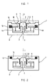
- Figures 1 and 2 illustrate an embodiment in which the capsule 1 is provided with a transducer 2 of the electrodynamic type.
- the capsule 1 comprises a case 3 made of non-magnetic material, open at one end 4, the end 4 being closed successively by the movable assembly 5 and by a mechanical protection cover 15 made of non-magnetic material.
- the moving element 5 comprises a central membrane 6, integral with a main coil 7 connected to two terminals of the shoemaker by flexible wires not shown in the figures.
- the central membrane 6 - main coil 7 assembly is held suspended in the housing 3 by an elastic annular peripheral suspension 8, formed of a membrane with concentric undulations, the suspension connecting the circular periphery of the central membrane 6 and a rigid peripheral support 9 itself secured along its periphery to the housing 3.
- the main coil 7 partially penetrates into the air gap 10 of a permanent magnet 11 disposed inside the case 3, as shown in FIG. 1.
- the magnetic field radiated by the main coil 7 is insufficient to excite a hearing aid.
- an auxiliary coil 12 fixedly mounted, is also inserted in the case 3. in the case, formed of a conductive wire wound around an insulating tubular frame 13 secured to the case 3. The ends of the wire of the auxiliary coil 12 are electrically connected in series or in parallel with the main coil 7.
- the auxiliary coil 12 produces a magnetic field, image of the electrical signals received by the capsule, and capable of radiating out of the housing 3 to be picked up by a hearing aid for the hearing impaired.
- the auxiliary coil 12 is arranged in the housing 3 concentric with the main coil 7, that is to say admitting the same axis of symmetry I-I.
- the auxiliary coil 12 is electrically connected with respect to the main coil 7 in a direction ensuring the production of a magnetic field in phase with the magnetic field produced by the main coil 7. In fact, if the connection is opposite, magnetic losses appear which are functions of the two radiated fields, losses caused by the contradictory radiations.
- auxiliary coil 12 it is particularly important to be able to introduce the auxiliary coil 12 at the same time as the manufacture of the capsule 1. In fact, it is then possible to identify the terminals of the various coils, and thus to ensure that the connections are correct in order to produce magnetic fields in phase.
- the double coil capsule certainly provides optimum performance due to this identification of the poles during manufacture.
- the connection of the coils can also be done by simple soldering, without the need for additional connectors, which tends to significantly reduce the cost of the device.
- the main coil 7 - membrane 6 - suspension 8 - rigid support 9 assembly forms a sub-assembly called mobile assembly 5.
- the mobile assembly during the manufacture of the capsule, is mounted separately and is attached then in the case 3. It is then preferable to fix the auxiliary coil 12 directly on the rigid support 9, which allows the assembly of this auxiliary coil 12 during the manufacture of the moving element 5.
- the auxiliary coil 12 forms thus with the moving assembly 5 a compact sub-assembly.
- the frame 13 of the auxiliary coil 12 is secured to the rigid support 9. It is possible to wind the wire in a single operation, the same wire forming on the one hand the main coil 7, and on the other hand the auxiliary coil 12, which avoids at the same time the location of the terminals of the two coils.
- a rigid peripheral support 9 comprising a shoulder 14 forming a cylindrical outer surface to act as a frame and to receive the wire from the auxiliary coil 12.
- the additional cost achieved by the addition of an additional copper mass represents a small percentage of the price of the transducer. This increase in cost is reasonable taking into account the technical advantages acquired. It thus becomes possible to manufacture, with modern technologies, efficient transducers for telephony and compatible with hearing aids for the hearing impaired.
- the auxiliary coil must not disturb the operation of the main coil. In particular, care should be taken to prevent the insertion of the auxiliary coil from causing the acoustic efficiency of the transducer to drop. This can be done by connecting the main coil and the auxiliary coil electrically in parallel, and choosing an auxiliary coil which has an electrical impedance at least eight to ten times greater than that of the main coil.
- the main coil 7 and the auxiliary coil 12 are connected in series; in this case, the auxiliary coil 12 has an electrical impedance at least eight to ten times lower than that of the main coil 7.
Applications Claiming Priority (2)
| Application Number | Priority Date | Filing Date | Title |
|---|---|---|---|
| FR8412102 | 1984-07-18 | ||
| FR8412102A FR2571581B1 (fr) | 1984-07-18 | 1984-07-18 | Capsule receptrice telephonique compatible avec les protheses auditives pour malentendants |
Publications (1)
| Publication Number | Publication Date |
|---|---|
| EP0169792A1 true EP0169792A1 (de) | 1986-01-29 |
Family
ID=9306643
Family Applications (1)
| Application Number | Title | Priority Date | Filing Date |
|---|---|---|---|
| EP85420131A Withdrawn EP0169792A1 (de) | 1984-07-18 | 1985-07-17 | Telefonhörerkapsel kompatibel mit Hörhilfen für Schwerhörige |
Country Status (2)
| Country | Link |
|---|---|
| EP (1) | EP0169792A1 (de) |
| FR (1) | FR2571581B1 (de) |
Cited By (5)
| Publication number | Priority date | Publication date | Assignee | Title |
|---|---|---|---|---|
| EP0565181A1 (de) * | 1992-04-09 | 1993-10-13 | Koninklijke Philips Electronics N.V. | Dynamische Hörerkapsel für einen Telefonhörer |
| US6078675A (en) * | 1995-05-18 | 2000-06-20 | Gn Netcom A/S | Communication system for users of hearing aids |
| WO2000060900A2 (en) * | 1999-04-07 | 2000-10-12 | Ericsson, Inc. | Hearing aid compatible piezoelectric speaker |
| FR2807262A1 (fr) * | 2000-04-03 | 2001-10-05 | Sagem | Telephone mobile avec haut-parleur perfectionne |
| WO2021007983A1 (zh) * | 2019-07-15 | 2021-01-21 | 苏州茹声电子有限公司 | 一种多路输入驱动的扬声器 |
Citations (6)
| Publication number | Priority date | Publication date | Assignee | Title |
|---|---|---|---|---|
| US2160829A (en) * | 1935-08-19 | 1939-06-06 | Carl W Cherry | Method and device for auxiliary transmission for telephone receivers |
| US2524393A (en) * | 1947-12-06 | 1950-10-03 | E A Myers & Sons | Noise reducing hearing aid case |
| US2554834A (en) * | 1948-06-29 | 1951-05-29 | Bell Telephone Labor Inc | Coupling for telephone receivers and hearing aid sets |
| US2656421A (en) * | 1950-10-21 | 1953-10-20 | E A Myers & Sons Inc | Wearable hearing aid with inductive pickup for telephone reception |
| FR1178594A (fr) * | 1957-11-23 | 1959-05-12 | Appareil auxiliaire d'écoute | |
| DE1133761B (de) * | 1954-04-26 | 1962-07-26 | Fred R Beyer | Handmikrophon fuer Diktiergeraete |
-
1984
- 1984-07-18 FR FR8412102A patent/FR2571581B1/fr not_active Expired
-
1985
- 1985-07-17 EP EP85420131A patent/EP0169792A1/de not_active Withdrawn
Patent Citations (6)
| Publication number | Priority date | Publication date | Assignee | Title |
|---|---|---|---|---|
| US2160829A (en) * | 1935-08-19 | 1939-06-06 | Carl W Cherry | Method and device for auxiliary transmission for telephone receivers |
| US2524393A (en) * | 1947-12-06 | 1950-10-03 | E A Myers & Sons | Noise reducing hearing aid case |
| US2554834A (en) * | 1948-06-29 | 1951-05-29 | Bell Telephone Labor Inc | Coupling for telephone receivers and hearing aid sets |
| US2656421A (en) * | 1950-10-21 | 1953-10-20 | E A Myers & Sons Inc | Wearable hearing aid with inductive pickup for telephone reception |
| DE1133761B (de) * | 1954-04-26 | 1962-07-26 | Fred R Beyer | Handmikrophon fuer Diktiergeraete |
| FR1178594A (fr) * | 1957-11-23 | 1959-05-12 | Appareil auxiliaire d'écoute |
Cited By (9)
| Publication number | Priority date | Publication date | Assignee | Title |
|---|---|---|---|---|
| EP0565181A1 (de) * | 1992-04-09 | 1993-10-13 | Koninklijke Philips Electronics N.V. | Dynamische Hörerkapsel für einen Telefonhörer |
| US6078675A (en) * | 1995-05-18 | 2000-06-20 | Gn Netcom A/S | Communication system for users of hearing aids |
| WO2000060900A2 (en) * | 1999-04-07 | 2000-10-12 | Ericsson, Inc. | Hearing aid compatible piezoelectric speaker |
| WO2000060900A3 (en) * | 1999-04-07 | 2001-02-15 | Ericsson Inc | Hearing aid compatible piezoelectric speaker |
| US6658126B1 (en) | 1999-04-07 | 2003-12-02 | Ericsson Inc. | Hearing aid compatible piezoelectric speaker |
| FR2807262A1 (fr) * | 2000-04-03 | 2001-10-05 | Sagem | Telephone mobile avec haut-parleur perfectionne |
| EP1146771A1 (de) * | 2000-04-03 | 2001-10-17 | Sagem Sa | Mobiltelefon mit einem verbesserten Lautsprecher |
| WO2021007983A1 (zh) * | 2019-07-15 | 2021-01-21 | 苏州茹声电子有限公司 | 一种多路输入驱动的扬声器 |
| US11882423B2 (en) | 2019-07-15 | 2024-01-23 | Suzhou Rusheng Electronics Co., Ltd. | Multi-input-driving loudspeaker |
Also Published As
| Publication number | Publication date |
|---|---|
| FR2571581A1 (fr) | 1986-04-11 |
| FR2571581B1 (fr) | 1987-01-16 |
Similar Documents
| Publication | Publication Date | Title |
|---|---|---|
| US3870832A (en) | Implantable electromagnetic hearing aid | |
| EP1353531B1 (de) | Akustischer Wandler mit reduzierter Dicke | |
| US6031922A (en) | Microphone systems of reduced in situ acceleration sensitivity | |
| EP1522208B1 (de) | Teilplantierbares hörhilfegerät | |
| US6324907B1 (en) | Flexible substrate transducer assembly | |
| FR2671683A1 (fr) | Haut-parleur a radiateur a dome. | |
| FR2504343A1 (fr) | Prothese auditive | |
| JP2003032797A (ja) | エレクトレットアッセンブリが端カバーに設けられた円筒形マイクロホン | |
| US7706559B2 (en) | Apparatus for suppressing radio frequency interference in a microphone assembly with preamplifier | |
| EP0169792A1 (de) | Telefonhörerkapsel kompatibel mit Hörhilfen für Schwerhörige | |
| US6370257B1 (en) | Apparatus including an electroacoustic transducer having terminal contacts which extend in the direction of the transducer axis and including a printed circuit board having mating contacts | |
| CA2066262C (en) | Piezoelectric sound generator and method of its manufacture | |
| FR2472899A1 (fr) | Transducteur electro-acoustique | |
| EP0336860A1 (de) | Elektroakustische Kapsel mit angekoppelter Spule | |
| US4608463A (en) | Electro-acoustic transducer | |
| US6909613B2 (en) | Assembly comprising an electrical element | |
| FR2832019A1 (fr) | Hydrophone a inhibition automatique en cas de depassement d'un seuil d'immersion ajustable | |
| US6038327A (en) | Electroacoustic transducer comprising a closing member for closing the rear volume of the transducer | |
| FR2559984A1 (fr) | Microphone auriculaire de contact | |
| JPS5979700A (ja) | 振動検知装置 | |
| US11600435B2 (en) | Coil bobbin for a balanced armature receiver | |
| JP4603124B2 (ja) | 多機能型発音体 | |
| FR2490439A1 (fr) | Transducteur electrodynamique en particulier pour la telephonie | |
| US11683648B2 (en) | Acoustic microphone with integrated magnetic transducer | |
| FR2587162A1 (fr) | Dispositif de fermeture de chambre acoustique pour un transducteur electroacoustique monte dans un boitier |
Legal Events
| Date | Code | Title | Description |
|---|---|---|---|
| PUAI | Public reference made under article 153(3) epc to a published international application that has entered the european phase |
Free format text: ORIGINAL CODE: 0009012 |
|
| AK | Designated contracting states |
Designated state(s): AT BE CH DE GB IT LI LU NL SE |
|
| STAA | Information on the status of an ep patent application or granted ep patent |
Free format text: STATUS: THE APPLICATION HAS BEEN WITHDRAWN |
|
| 18W | Application withdrawn |
Withdrawal date: 19860630 |
|
| 18D | Application deemed to be withdrawn |
Effective date: 19860930 |
|
| RIN1 | Information on inventor provided before grant (corrected) |
Inventor name: GUILLOU, DENIS |