EP0169730A1 - Minderung einer Fluidumaufwirbelung - Google Patents
Minderung einer Fluidumaufwirbelung Download PDFInfo
- Publication number
- EP0169730A1 EP0169730A1 EP85305239A EP85305239A EP0169730A1 EP 0169730 A1 EP0169730 A1 EP 0169730A1 EP 85305239 A EP85305239 A EP 85305239A EP 85305239 A EP85305239 A EP 85305239A EP 0169730 A1 EP0169730 A1 EP 0169730A1
- Authority
- EP
- European Patent Office
- Prior art keywords
- breather
- breather tube
- nose
- buffet
- breathers
- Prior art date
- Legal status (The legal status is an assumption and is not a legal conclusion. Google has not performed a legal analysis and makes no representation as to the accuracy of the status listed.)
- Withdrawn
Links
- 239000012530 fluid Substances 0.000 title claims abstract description 7
- 230000005284 excitation Effects 0.000 title description 11
- 230000036962 time dependent Effects 0.000 claims abstract description 5
- 238000007654 immersion Methods 0.000 claims abstract 2
- 235000021170 buffet Nutrition 0.000 claims description 20
- 238000000926 separation method Methods 0.000 description 6
- 230000000694 effects Effects 0.000 description 5
- 230000035939 shock Effects 0.000 description 4
- 238000012360 testing method Methods 0.000 description 3
- 238000011144 upstream manufacturing Methods 0.000 description 3
- 230000002238 attenuated effect Effects 0.000 description 2
- 238000001816 cooling Methods 0.000 description 2
- 238000005259 measurement Methods 0.000 description 2
- 230000010355 oscillation Effects 0.000 description 2
- 238000013459 approach Methods 0.000 description 1
- 230000015556 catabolic process Effects 0.000 description 1
- 238000010276 construction Methods 0.000 description 1
- 230000003247 decreasing effect Effects 0.000 description 1
- 230000001419 dependent effect Effects 0.000 description 1
- 238000009434 installation Methods 0.000 description 1
- 230000003993 interaction Effects 0.000 description 1
- 230000000737 periodic effect Effects 0.000 description 1
- 230000000750 progressive effect Effects 0.000 description 1
- 230000008929 regeneration Effects 0.000 description 1
- 238000011069 regeneration method Methods 0.000 description 1
- 230000029058 respiratory gaseous exchange Effects 0.000 description 1
- 239000000523 sample Substances 0.000 description 1
- 229910010271 silicon carbide Inorganic materials 0.000 description 1
- 230000001629 suppression Effects 0.000 description 1
- 238000012546 transfer Methods 0.000 description 1
- XLYOFNOQVPJJNP-UHFFFAOYSA-N water Substances O XLYOFNOQVPJJNP-UHFFFAOYSA-N 0.000 description 1
Images



Classifications
-
- B—PERFORMING OPERATIONS; TRANSPORTING
- B64—AIRCRAFT; AVIATION; COSMONAUTICS
- B64C—AEROPLANES; HELICOPTERS
- B64C1/00—Fuselages; Constructional features common to fuselages, wings, stabilising surfaces or the like
-
- B—PERFORMING OPERATIONS; TRANSPORTING
- B64—AIRCRAFT; AVIATION; COSMONAUTICS
- B64C—AEROPLANES; HELICOPTERS
- B64C21/00—Influencing air flow over aircraft surfaces by affecting boundary layer flow
-
- E—FIXED CONSTRUCTIONS
- E04—BUILDING
- E04B—GENERAL BUILDING CONSTRUCTIONS; WALLS, e.g. PARTITIONS; ROOFS; FLOORS; CEILINGS; INSULATION OR OTHER PROTECTION OF BUILDINGS
- E04B1/00—Constructions in general; Structures which are not restricted either to walls, e.g. partitions, or floors or ceilings or roofs
- E04B1/62—Insulation or other protection; Elements or use of specified material therefor
- E04B1/92—Protection against other undesired influences or dangers
- E04B1/98—Protection against other undesired influences or dangers against vibrations or shocks; against mechanical destruction, e.g. by air-raids
-
- E—FIXED CONSTRUCTIONS
- E04—BUILDING
- E04H—BUILDINGS OR LIKE STRUCTURES FOR PARTICULAR PURPOSES; SWIMMING OR SPLASH BATHS OR POOLS; MASTS; FENCING; TENTS OR CANOPIES, IN GENERAL
- E04H12/00—Towers; Masts or poles; Chimney stacks; Water-towers; Methods of erecting such structures
-
- F—MECHANICAL ENGINEERING; LIGHTING; HEATING; WEAPONS; BLASTING
- F01—MACHINES OR ENGINES IN GENERAL; ENGINE PLANTS IN GENERAL; STEAM ENGINES
- F01D—NON-POSITIVE DISPLACEMENT MACHINES OR ENGINES, e.g. STEAM TURBINES
- F01D5/00—Blades; Blade-carrying members; Heating, heat-insulating, cooling or antivibration means on the blades or the members
- F01D5/12—Blades
- F01D5/14—Form or construction
- F01D5/141—Shape, i.e. outer, aerodynamic form
- F01D5/145—Means for influencing boundary layers or secondary circulations
-
- F—MECHANICAL ENGINEERING; LIGHTING; HEATING; WEAPONS; BLASTING
- F15—FLUID-PRESSURE ACTUATORS; HYDRAULICS OR PNEUMATICS IN GENERAL
- F15D—FLUID DYNAMICS, i.e. METHODS OR MEANS FOR INFLUENCING THE FLOW OF GASES OR LIQUIDS
- F15D1/00—Influencing flow of fluids
- F15D1/0005—Baffle plates
-
- Y—GENERAL TAGGING OF NEW TECHNOLOGICAL DEVELOPMENTS; GENERAL TAGGING OF CROSS-SECTIONAL TECHNOLOGIES SPANNING OVER SEVERAL SECTIONS OF THE IPC; TECHNICAL SUBJECTS COVERED BY FORMER USPC CROSS-REFERENCE ART COLLECTIONS [XRACs] AND DIGESTS
- Y02—TECHNOLOGIES OR APPLICATIONS FOR MITIGATION OR ADAPTATION AGAINST CLIMATE CHANGE
- Y02T—CLIMATE CHANGE MITIGATION TECHNOLOGIES RELATED TO TRANSPORTATION
- Y02T50/00—Aeronautics or air transport
- Y02T50/10—Drag reduction
-
- Y—GENERAL TAGGING OF NEW TECHNOLOGICAL DEVELOPMENTS; GENERAL TAGGING OF CROSS-SECTIONAL TECHNOLOGIES SPANNING OVER SEVERAL SECTIONS OF THE IPC; TECHNICAL SUBJECTS COVERED BY FORMER USPC CROSS-REFERENCE ART COLLECTIONS [XRACs] AND DIGESTS
- Y02—TECHNOLOGIES OR APPLICATIONS FOR MITIGATION OR ADAPTATION AGAINST CLIMATE CHANGE
- Y02T—CLIMATE CHANGE MITIGATION TECHNOLOGIES RELATED TO TRANSPORTATION
- Y02T50/00—Aeronautics or air transport
- Y02T50/60—Efficient propulsion technologies, e.g. for aircraft
Definitions
- the present invention relates to the alleviation of the level of fluid buffet excitation.
- it is concerned with minimising the effect of airflow buffet on aircraft surfaces and on vehicles and buildings such as chimneys and cooling, and other towers.
- waterborne craft including oil rigs.
- aircraft surfaces, vehicles, buildings and craft are hereinafter called bodies.
- a body liable to buffet excitation from fluid flow incorporates a breather tube connected between orifices on the surface of the body where time mean pressures are similar while time dependent measures would but for their presence be substantially 180° out of phase.
- the breather tube may connect two orifices each on opposite sides of the body, and preferably the tube is straight.
- the orifice effective diameter may be between 1 mm - 10 cm, dependent on the form, type and size of the body and the nature and severity of the buffet to be encountered.
- the orifice, or orifices may be round.
- a low frequency shock oscillation observed as heavy buffeting at about 2-3 Hz in flight at transonic speeds, was simulated with a 1/8 scale wind tunnel model at a frequency of 21 Hz.
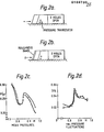
- the buffet was strongly attenuated by opening four "buffet breathers" - connections in accordance with the invention - close to the mean shock position.
- the breather tube be stoppable at the orifices for all non-buffet conditions. Traps which may be slid open or open into the tubes may be arranged to effect breather tube stopping. Moreover a sensor may be deployed for sensing the onset of buffet and effecting trap opening and closure. It should nevertheless be noted that breather tubes in accordance with the invention are less likely to be incorporated between upper and lower surfaces of such lifting aerofoils as aircraft mainplanes and tailplanes, for fear of lift decrement and drag, than they are in various fairing situations.
- a tube may be of value between port and starboard upper surfaces of a slender delta aircraft or weapon, for use in regimes where vortices are shed from alternate sides. Moreover they may be of value as perforations at the trailing edge of any aerofoil, including a lifting aerofoil.
- a breathing tube may be established between similar locations on either side of a fuselage nose, particularly a sharp nose, to alleviate assymetric vortices and sideforces generated thereby at high angels of incidence.
- the orifices may be on a nose cone rotatable to maintain a symmetrical hole configuration with respect to the incidence plane.
- the diameter of the tube and orifices necessary to achieve attenuation depends upon the required tube length, the likely severity of the buffet and buffet frequency, and may be determined from the NLR Report 238 of 1965 by H Bergh and H Tijdeman. For reasons of mass reduction the smallest possible tube is likely to be preferred.
- breathers In the context of a cylinder subject to flows of varying direction, breathers spaced spanwise at half cylinder diameter intervals, with adjacent breathers at 90° one to another, have been found adequate. As for bodies with considerable chord, on an aerofoil fairing, the breathers are preferably in the region of t/c max and may not need repeating in the chord direction, while on a slender delta wing the primary breather tube may be as close to the nose as possible and a repeater sited wherever vortex regeneration is likely.
- Figure 1 is a plan view of the fairing, and Figures 1 (b), (c), (d) are side elevations showing the location of breather orifices 10, of which corresponding orifices on each side are connectedby tubes 11.
- a pressure transducer 12 is sited aft of a station between the two inboard mast holes.
- Figure 4 shows that these results are not peculiar to the single transducer position considered, which is close to the fuselage to accentuate shock boundary layer interaction effects.
- the pressure transducer is displaced along the shoulder away from the fuselage (Fig 4 (a), (b)) the mean pressure is increased (lower supervelocities) and the severity of the rms pressure fluctuations is decreased.
- the choice of a transducer position close to the fuselage for the main series of tests was justified.
- the right circular cylinder illustated in Figure 5 is a construction which, whether taking the form of a water tower, cooling tower, communications tower, strut or submarine periscope or oil rig underwater member, may be liable to excitation in fluid flow by the shedding of Karman vortices.
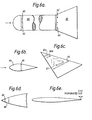
- Figure 6 (a) illustrates a re-entry body having a bluff nose 60 and a flared'tail 61. This configuration, necessary for the minimisation of heat transfer, is liable to violent buffet excitation at transonic speeds.
- Breathers 62 are shown provided through the nose, at the base thereof, to attenuate these unsteady pressures. Sometimes the flows over the flare will separate and become unsteady, giving rise to a loss of stability. Some improvement is obtained by locating breathers 63 at the base of the flare.
- Figure 6(b) illustrates a fairing 64 having a breather tube 65 between orifices a corresponding locations on either side, just aft of t/c max.
- Figure 6(c) illustrates the use of breathers in a slender wing aircraft configuration.
- Buffet breathers 66,67 extending between corresponding upper surface orifices port and starboard serve to attenuate this vortex shedding. Separate buffet breathers are provided for the primary (66) and secondary (67) vortices.
- the breathers 66a, 67a closest to the apex will be most effective for two reasons:
- the breathers 67 between the pair of secondary vortices may not needed, if the primary vortices are steady.
- the strength of the mean vortex flow should be increased by the suppression of time-dependent separated flow vortices, with a consequent small increase in lift coefficient for a given angle of incidence.
- the breathers 66,67 have traps (not shown) at the orifice, openable into the breathers.
- Figure 6(d) illustrates such a nose having a nose cone 68 with a breather 69 passing between two orifices 1 mm diameter, 60° apart and 5 mm from the nose, the cone being rotatable to maintain the orifices each 120° from bdc about incidence plane.
- Figure 6(e) illustrates a wing which is 0.02X perforated over the trailing 0.01 chord, to alleviate aerodynamic trailing edge separated flow noise.
Landscapes
- Engineering & Computer Science (AREA)
- Mechanical Engineering (AREA)
- Aviation & Aerospace Engineering (AREA)
- Architecture (AREA)
- Physics & Mathematics (AREA)
- Civil Engineering (AREA)
- Structural Engineering (AREA)
- Fluid Mechanics (AREA)
- General Engineering & Computer Science (AREA)
- Environmental & Geological Engineering (AREA)
- Electromagnetism (AREA)
- Earth Drilling (AREA)
Applications Claiming Priority (2)
| Application Number | Priority Date | Filing Date | Title |
|---|---|---|---|
| GB848419158A GB8419158D0 (en) | 1984-07-27 | 1984-07-27 | Fluid buffet excitation alleviation |
| GB8419158 | 1984-07-27 |
Publications (1)
| Publication Number | Publication Date |
|---|---|
| EP0169730A1 true EP0169730A1 (de) | 1986-01-29 |
Family
ID=10564540
Family Applications (1)
| Application Number | Title | Priority Date | Filing Date |
|---|---|---|---|
| EP85305239A Withdrawn EP0169730A1 (de) | 1984-07-27 | 1985-07-23 | Minderung einer Fluidumaufwirbelung |
Country Status (2)
| Country | Link |
|---|---|
| EP (1) | EP0169730A1 (de) |
| GB (1) | GB8419158D0 (de) |
Cited By (2)
| Publication number | Priority date | Publication date | Assignee | Title |
|---|---|---|---|---|
| EP0208360A3 (de) * | 1985-07-08 | 1988-01-27 | Saab-Scania Aktiebolag | Vorrichtung für die Giersteuerung eines Flugzeugs |
| EP0209171A3 (de) * | 1985-07-08 | 1988-01-27 | Saab-Scania Aktiebolag | Vorrichtung für die Giermomentsteuerung eines Flugzeugs |
Citations (4)
| Publication number | Priority date | Publication date | Assignee | Title |
|---|---|---|---|---|
| BE358128A (de) * | ||||
| GB736835A (en) * | 1952-09-11 | 1955-09-14 | Maschf Augsburg Nuernberg Ag | Improvements in or relating to blading for axial flow turbo-engines |
| DE1216515B (de) * | 1963-07-31 | 1966-05-12 | Beteiligungs & Patentverw Gmbh | Aufrecht stehender, rohrfoermiger Koerper, z. B. Mast |
| FR2439157A1 (fr) * | 1978-10-17 | 1980-05-16 | Freudenberg Carl | Dispositif de saisie, notamment pour pieces de revolution |
-
1984
- 1984-07-27 GB GB848419158A patent/GB8419158D0/en active Pending
-
1985
- 1985-07-23 EP EP85305239A patent/EP0169730A1/de not_active Withdrawn
Patent Citations (4)
| Publication number | Priority date | Publication date | Assignee | Title |
|---|---|---|---|---|
| BE358128A (de) * | ||||
| GB736835A (en) * | 1952-09-11 | 1955-09-14 | Maschf Augsburg Nuernberg Ag | Improvements in or relating to blading for axial flow turbo-engines |
| DE1216515B (de) * | 1963-07-31 | 1966-05-12 | Beteiligungs & Patentverw Gmbh | Aufrecht stehender, rohrfoermiger Koerper, z. B. Mast |
| FR2439157A1 (fr) * | 1978-10-17 | 1980-05-16 | Freudenberg Carl | Dispositif de saisie, notamment pour pieces de revolution |
Cited By (2)
| Publication number | Priority date | Publication date | Assignee | Title |
|---|---|---|---|---|
| EP0208360A3 (de) * | 1985-07-08 | 1988-01-27 | Saab-Scania Aktiebolag | Vorrichtung für die Giersteuerung eines Flugzeugs |
| EP0209171A3 (de) * | 1985-07-08 | 1988-01-27 | Saab-Scania Aktiebolag | Vorrichtung für die Giermomentsteuerung eines Flugzeugs |
Also Published As
| Publication number | Publication date |
|---|---|
| GB8419158D0 (en) | 1984-08-30 |
Similar Documents
| Publication | Publication Date | Title |
|---|---|---|
| Mueller | Low Reynolds number vehicles | |
| US7234914B2 (en) | Apparatus and method for enhancing lift produced by an airfoil | |
| AU599974B2 (en) | Bodies with reduced surface drag | |
| EP3144218B1 (de) | Hecktriebwerksgondelform für ein flugzeug | |
| US20110260008A1 (en) | Fluid flow control device for an aerofoil | |
| US20110309202A1 (en) | Wingtec Holding Limited | |
| EP3144217A1 (de) | Luftfahrzeug mit einem heckmotor | |
| Huang et al. | Effects of freestream turbulence on wing-surface flow and aerodynamic performance | |
| Caruana et al. | Separated flow and buffeting control | |
| WENTZ, JR | Vortex-fin interaction on a fighter aircraft | |
| GB2070139A (en) | Inlet Cowl for Supersonic Aircraft Engine | |
| Campbell | Patterns in the sky: natural visualization of aircraft flow fields | |
| Peake et al. | Three-dimensional flow separations on aircraft and missiles | |
| Nichols et al. | Characterization and control of nacelle inlet flow in crosswind | |
| EP0169730A1 (de) | Minderung einer Fluidumaufwirbelung | |
| EP0052360A1 (de) | Luftansaugvorrichtung einer Flugzeug-Gasturbine | |
| Pohlen et al. | Boundary layer characteristics of the Miley airfoil at low Reynolds numbers | |
| GB2187261A (en) | Controlling boundary layer | |
| Pfenninger | FLOW PROBLEMS OF SWEPT LOW‐DRAG SUCTION WINGS OF PRACTICAL CONSTRUCTION AT HIGH REYNOLDS NUMBERS | |
| Leavitt | Effect of empennage location on twin-engine afterbody-nozzle aerodynamic characteristics at Mach Numbers from 0.6 to 1.2 | |
| RU2789419C1 (ru) | Способ устранения колебаний скачка уплотнения на профиле крыла гражданского самолета при трансзвуковых скоростях полета | |
| Manor et al. | Static and dynamic water tunnel tests of slender wings and wing-bodyconfigurations at extreme angles of attack | |
| Biber et al. | Flow study of supersonic wing-nacelle configuration | |
| Werlé | Water Tunnel Testing | |
| Anderson et al. | FLIGHT MEASUREMENTS OF THE LOW-SPEED CHARACTERISTICS |
Legal Events
| Date | Code | Title | Description |
|---|---|---|---|
| PUAI | Public reference made under article 153(3) epc to a published international application that has entered the european phase |
Free format text: ORIGINAL CODE: 0009012 |
|
| AK | Designated contracting states |
Designated state(s): DE FR GB IT |
|
| STAA | Information on the status of an ep patent application or granted ep patent |
Free format text: STATUS: THE APPLICATION HAS BEEN WITHDRAWN |
|
| 18W | Application withdrawn |
Withdrawal date: 19860418 |
|
| RIN1 | Information on inventor provided before grant (corrected) |
Inventor name: MABEY, DENNIS GEORGE |