EP0169281B1 - Coin-freed vending machine mechanism - Google Patents
Coin-freed vending machine mechanism Download PDFInfo
- Publication number
- EP0169281B1 EP0169281B1 EP19840305071 EP84305071A EP0169281B1 EP 0169281 B1 EP0169281 B1 EP 0169281B1 EP 19840305071 EP19840305071 EP 19840305071 EP 84305071 A EP84305071 A EP 84305071A EP 0169281 B1 EP0169281 B1 EP 0169281B1
- Authority
- EP
- European Patent Office
- Prior art keywords
- coin
- drawer
- coins
- packet
- mechanism according
- Prior art date
- Legal status (The legal status is an assumption and is not a legal conclusion. Google has not performed a legal analysis and makes no representation as to the accuracy of the status listed.)
- Expired
Links
- 230000007246 mechanism Effects 0.000 title claims description 28
- 230000008878 coupling Effects 0.000 claims description 2
- 238000010168 coupling process Methods 0.000 claims description 2
- 238000005859 coupling reaction Methods 0.000 claims description 2
- 230000000994 depressogenic effect Effects 0.000 claims description 2
- 230000000630 rising effect Effects 0.000 claims description 2
- 230000009471 action Effects 0.000 description 6
- 238000010586 diagram Methods 0.000 description 4
- 238000003780 insertion Methods 0.000 description 3
- 230000037431 insertion Effects 0.000 description 3
- 239000002184 metal Substances 0.000 description 3
- 238000009825 accumulation Methods 0.000 description 2
- 230000008859 change Effects 0.000 description 2
- 230000006835 compression Effects 0.000 description 2
- 238000007906 compression Methods 0.000 description 2
- 238000001514 detection method Methods 0.000 description 2
- 230000000694 effects Effects 0.000 description 2
- 230000009977 dual effect Effects 0.000 description 1
- 238000009434 installation Methods 0.000 description 1
- 238000000034 method Methods 0.000 description 1
- 230000007935 neutral effect Effects 0.000 description 1
- 230000004044 response Effects 0.000 description 1
Images



Classifications
-
- G—PHYSICS
- G07—CHECKING-DEVICES
- G07D—HANDLING OF COINS OR VALUABLE PAPERS, e.g. TESTING, SORTING BY DENOMINATIONS, COUNTING, DISPENSING, CHANGING OR DEPOSITING
- G07D5/00—Testing specially adapted to determine the identity or genuineness of coins, e.g. for segregating coins which are unacceptable or alien to a currency
- G07D5/02—Testing the dimensions, e.g. thickness, diameter; Testing the deformation
-
- G—PHYSICS
- G07—CHECKING-DEVICES
- G07F—COIN-FREED OR LIKE APPARATUS
- G07F11/00—Coin-freed apparatus for dispensing, or the like, discrete articles
- G07F11/02—Coin-freed apparatus for dispensing, or the like, discrete articles from non-movable magazines
- G07F11/04—Coin-freed apparatus for dispensing, or the like, discrete articles from non-movable magazines in which magazines the articles are stored one vertically above the other
- G07F11/16—Delivery means
- G07F11/20—Pushers actuated directly by hand
-
- G—PHYSICS
- G07—CHECKING-DEVICES
- G07F—COIN-FREED OR LIKE APPARATUS
- G07F5/00—Coin-actuated mechanisms; Interlocks
- G07F5/02—Coin-actuated mechanisms; Interlocks actuated mechanically by coins, e.g. by a single coin
- G07F5/06—Coin-actuated mechanisms; Interlocks actuated mechanically by coins, e.g. by a single coin wherein two or more coins of different denominations are required for each transaction
-
- G—PHYSICS
- G07—CHECKING-DEVICES
- G07F—COIN-FREED OR LIKE APPARATUS
- G07F5/00—Coin-actuated mechanisms; Interlocks
- G07F5/26—Interlocks, e.g. for locking the doors of compartments other than that to be used
Definitions
- This invention relates to coin or token-freed vending machines, for installation in public places.
- GB-A-2022898 there is described a coin-freed dispensing mechanism in which two different kinds of coins selected and distinguished by a coin measuring apparatus are accumulated in two respective columns stacked edge-on-edge and when a customer attempts to pull a drawer and obtain a vended packet a mechanical coin-detecting means is operated to detect whether the requisite numbers of coins forthe vend have been accumulated in the two columns.
- the columns of coins in the accumulator are disposed so that the coins in one column are substantially edge-to-edge horizontally with the coins in the other column and the coin-detection is performed by a single feeler that pushes horizontally against the edge of the top coin in one column and thereby that top coin is displaced slightly to push in its turn edge-to-edge against the top coin in the other column, whereby the check on the coin contents of both columns is performed by means of only the one feeler.
- This arrangement has been found to possess a number of restrictions in its use and it is an object of the present invention to provide an arrangement that is more versatile and reliable in its application.
- a mechanical coin-freed dispensing mechanism comprises coin measuring apparatus for accepting correctly-sized coins of at least two different sizes and rejecting wrongly-sized coins, and for separately routing the accepted coins of different sizes, coin-accumulating means to collect the accepted coins in at least a first column of coins of one sized stacked edge-on-edge and a second column of coins of a second size similarly stacked, mechanical coin-detecting means to detect if a requisite number of coins has accumulated in the coin-accumulating means, packet delivery means manually operable when unlocked to vend a packet and locking means for the packet delivery means which is coupled to the coin-detecting means to lock the packet delivery means and prevent a packet being vended if the coin detecting means fails to detect the requisite number of coins in the coin-accumulating means, the coins passing through the mechanism solely by coin energy and the coin-detecting means being operated by the manual effort of the customer each time a customer attempts to hand-operate the packet delivery means, characterised in that respective independent first and second detecting means are provided for said first
- the coin measuring apparatus comprises successive gates each defined by parallel inclined top and bottom rails with an adjustable gap between them, coins of a selected size fitting between and travelling along the rails while oversize coins do not fit and undersize coins fall through the gap.
- the packet delivery means comprise packet-vending drawers to be pulled out by the customer
- the coin detecting means comprise pairs of arms with coin-sensing fingers that are coupled to locking sears for the drawers, the coin detecting arms moving to seek the presence of the top one of the required number of coins in each column of the accumulating means when a customer attempts to pull a drawer and the drawer being locked by its locking sear if said top coins are not detected.
- Each drawer preferably contains a hinged flap that is depressed on to the bottom of the drawer if the drawer contains a packet to be vended but springs up when the drawer is empty and also when a vended packet is removed by the customer, this rising of the flap serving to lock the drawer, if the drawer has not been pulled out, and also denying access to the back of the drawer and the dispenser above if the drawer has been pulled out and a vended packet removed.
- the columns of coins in the coin accumulating means are supported on the upper edges of hinged coin deflector flaps coupled to further sears associated with the drawers and with a coin refund button, whereby when a drawer is pulled out the deflector flaps swing one way to allow the coins to fall from the accumulating means and to direct them into the coin boxes, and if a drawer is not pulled out but the refund button is operated the deflector flaps swing another way to allow the coins to fall into a refund chute returning them to the customer.
- the mechanism described herein controls the coinitoken-freed release of two independent dispensing drawers in a twin column packet vending machine, by selectively storing accepted coins of one single or two differing diameters in one or two accumulator columns, respectively, so as to allow for release of either drawer in response to accumulation of the same or differing coin totals in either or both columns, non-accepted (rejected) coins being returned to the user immediately.
- the mechanism will accept all coins/token discs which can pass through a restrictor slot of fixed dimensions and will select and accumulate coins of one or two specific diameters from those inserted, so that upon subsequent pulling of one or other of the two associated dispensing drawers there will be a coin freed drawer movement provided a certain coin total preset for the particular drawer that the user wishes to pull has accumulated made up of coins of either or both of the selected coin diameters, as required.
- the user can obtain return of all accumulated coins by pushing a "coin return” button prior to either drawer being successfully operated. Rejected coins are returned immediately following their insertion. Coins successfully selected by diameter are further subjected to a thickness check on entering the respective accumulator, which leads to the rejection of over-thick coins, these being returned as above to the user.
- the setting of accumulator coin-total sensors is achieved by moving slidable sensing fingers along vertical detented tracks so that their position coincides in each case with the horizontal centre line of the "final" coin of each required tally, four such sensors allowing a different coin total setting for each of the independent drawers, each of which totals can be made up of coins of either or both sizes.
- FIG. 1 The flow diagram of Figure 1 shows the general sequence of events following insertion of a coin into the dispenser. It should be noted that at all times the user's money is "safe", i.e. all accumulated coins are retrievable, prior to the successful operation of either drawer, by pressing the coin return button.
- a test is performed at a first gate 2 to determine if the coin diameter equals a first preset diameter x. If the answer is "yes” the coin is routed in the direction of a first accumulator 17 for coins of diameter x. If the coin diameter is too small the coin is ejected for return to the user at a refund cup 16. If the coin is too big it passes for test at a second gate 3 to determine if the coin diameter equals a second and larger preset diameter y. If the answer is "yes” the coin is routed in the direction of a second accumulator 18 for coins of diameter y. If the coin is too small or too big it is rejected to the refund cup 16.
- Coins of diameter x en route to the accumulator 17 are subjected at 5 to a thickness test; if a coin is too thick it is rejected to the refund cup.
- Coins of diameter y en route to the accumulator 18 are likewise subjected at 4 to a thickness test and coins that are too thick rejected to the refund cup.
- Coins of diameters x and y that pass the thickness test are stacked in the accumulators 17 and 18 respectively.
- the user can obtain return of the coins stacked in the accumulators 17 and 18 by pressing the coin return button 6. If the left-hand drawer 7 is pulled, the right-hand drawer 8 is locked, and vice versa, and if either drawer is pulled the coin return button 6 is disabled. Before a drawer is released, both the sensor 9 of the accumulator 17 and the sensor 10 of the accumulator 18 must be registering the presence of the required tally of coins in the respective accumulator. If either sensor is not registering the required tally, the drawers remain locked, as at 11 or 12. When a drawer has been released and pulled, as at 13, all the coins stacked in the accumulators pass into the coinboxes of the machine, as at 14. The operating cycle is completed by automatic re-locking of the drawer, at 15, when the drawer is returned after removal of the dispensed packet.
- Each gate selects coins within a specified diameter tolerance band (X ⁇ 0.35 mm or Y ⁇ 0.35 mm) for accumulation. Selected coins S fit between the top and bottom rails, undersize coins R fall through, and oversize coins P cannot fit beneath the top rail.
- Each gate top plate 19 or 20 carries two location pins 22 which, in conjunction with a respective pair of pins 23 on the main structure 24 of the selector/rejector, allow accurate positioning of the plates 19, 20 by accurate setting of the pin centre lines dimension "D", without recourse to trial and error methods with coins.
- These settings are made by using pre-drilled templates unique to each particular coin type, which templates are removable parts of the accumulator assembly, in that they also serve as coin gauge plates in the respective accumulator columns.
- the total part change requirement is limited to a single coin gauge plate exchange-the new plate also serving to allow accurate re-adjustment of the respective gate dimension "D" so as to select coins of type C.
- Each gate 2, 3 is, in effect, a pair of associated diameter sensing elements offering triple choice of the result (oversize or correct size or undersize) in a single coin pass, rather than the normal dual choice (oversize or undersize). This considerably simplifies the task of selecting two differing coin diameters from all those inserted into the unit.
- the coin accumulator unit is shown in Figures 4 to 7.
- This device accepts coins of one or two diameter sizes arriving through two separate chutes from the selector/rejector assembly mounted above it, and stacks them in two vertical columns 25,26 so the coins 27 rest edge-on-edge with their rims presented for detection by the adjacent coin sensor assembly.
- the column widths are set at approximately 1.25xcoin thickness in each case, there being face plates 29, 30 secured to opposite sides of the accumulator body 28 each of which defines with the body 28 a slot 31 or 32 to suit the particular coin.
- Each face plate 29, 30 is a piece of flat sheet metal with the top portion 35 cranked outwards to form a coin chute (Figure 7).
- each coin gauge plate 85, 86 which is replaceable, being, as already described, the actual template utilized to set the respective selector/rejector gate dimension "D". Since each coin gauge plate is clamped between the respective face plate 29, 30 and the accumulator body 28, it also determines, by its thickness, the width of the respective coin slot 31, 32. Coins of greater thickness than the respective column width are unable to enter the top of the slot 31 or 32 but are arrested on an inclined hard metal coin check bar 33 set into the accumulator body 28 at the throat of the coin chute defined between the accumulator body and the cranked portion 35 of the respective face plate 29, 30.
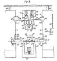
- the coin sensor assembly is shown in Figure 8.
- This assembly comprises two pairs of sensing fingers 37, 38, one pair for each coin column, carried on pivotally-mounted arms 39, 40.
- the right hand arms of each pair are connected by links 41 to sears 46 cooperating with a cam profile 42 on the left hand drawer 7, and the left hand arms are likewise connected by links 43 to sears 47 cooperating with a cam profile 44 on the right hand drawer 8.
- Each pair of arms has a tension spring 45 pulling the arms toward one another.
- both fingers 37 and 39 will be arrested by encountering coins 27 and the drawer is released. But if only one of the columns does not contain enough coins, the respective finger and arm will not be arrested, as a consequence of which at least one of the two sears 46 or 47 appertaining to that drawer will fully enter a recess 48 or 49 in the drawer and lock it against further movement. Assuming, however, the drawer is released, the sears 46 or 47 will only effect slight entry into the recess 48 or 49 and will then be cammed out again by a profile 50 or 51, thereby returning the fingers 37, 38 to the rest position out of contact with the coins 27 so that they will not interfere with subsequent dropping of the coins into the coin boxes.
- a further drawer cam/sear arrangement comprises two opposed abutting bars 52, 53 urged toward one another by a spring 92, and a freely slidable sear-ended interlock bar 90 which cooperates at one end with a recess 54 and cam profile 55 of the left-hand drawer 7, and at the other with a recess 56 and cam profile 57 of the right-hand drawer 8. If one drawer is pulled the interlock bar 90 is cammed in the direction of the other drawer by the cam profile 55 or 57 on the pulled drawer, thereby immediately locking the other drawer by entry of the relevant sear-shaped end 91 into its recess 56 or 54.
- the coins 27 in the two accumulator slots 31, 32 are supported on the upper edges of two coin deflector flaps 59, hinged near their lower edges, as at 62, and held upright against the action of a compression spring 60 by engagement of their edges with shoulders 61 on the bars 52, 53.
- the two deflector flaps are so linked to one another that they are constrained to swing inward toward one another in unison or outward away from one another in unison.
- both bars 52, 53 On pulling of a drawer, the movement of both bars 52, 53 to the left or right, as the case may be, results in one of the bar shoulders 61 pushing one deflector flap inward against the action of the spring 60, so that both flaps 59 are caused to swing inward whereby the coins in both accumulator columns are allowed to fall and are directed by the flaps 59 outward into the machine coin boxes 63.
- a refund button 64 at the front of the machine can be pushed inward against the action of a compression spring 65, whereupon inwardly directed cam fingers 66 on the refund button engage pins 67 on the bars 52, 53 and cam both bars outwardly away from one another against the action of the interconnecting spring 92.
- Each drawer has a return spring 69 and a two- way ratchet mechanism that is disengaged both when the drawer is fully home and when it is pulled right out but runs into engagement soon after opening or closing movement of the drawer is commenced.
- This mechanism comprises a rack 96 with triangular teeth on the drawer, and a cooperating square-nosed pawl 97 pivoted on the machine frame and having a spring 98 keeping it in a centred or neutral position when it is out of engagement with the rack teeth.
- the ratchet commences to operate on the moving drawer so that return of the drawer is positively prevented until nearly full extension of the drawer is achieved.
- Figure 9 shows detail of a drawer 7 or 8.
- a thin substantially horizontal rectangular flap 70 lies in a recess 71 in the bottom of each drawer near the back end of the drawer and is hinged at its rear edge, at 72, the hinge axis extending horizontally across the drawer.
- the flap 70 is lightly spring-loaded by a spring 73 which, if the drawer is empty, urges the flap up out of the recess 71 into a position in which the front edge 74 of the flap is raised to the level of the tops of the drawer sides 75.
- Two hooked extensions 76 on the rear of the flap 70 behind the hinge line project downwards through holes 77 in the drawer bottom and, when the flap rises under the spring force acting on it, the hooks 76 are lowered, to engage with rearwardly and upwardly directed projections 78 pressed up from the metal of the fixed chassis 79 of the dispenser if an attempt is made to pull out the empty drawer. By this means the drawer is locked when empty.
- the flap lies flat in the bottom of the drawer under the weight of the packet and the hooks 76 are raised clear of the projections 78 so that they do not prevent pulling out of the drawer.
- a leaf spring 80 attached to the chassis 79 under the drawer is arranged to engage a downward protuberance 81 on the flap 70 just forward of the hinge 72 so as to considerably increase the upward spring force on the flap during the final part of drawer outward travel.
Landscapes
- Physics & Mathematics (AREA)
- General Physics & Mathematics (AREA)
- Control Of Vending Devices And Auxiliary Devices For Vending Devices (AREA)
Description
- This invention relates to coin or token-freed vending machines, for installation in public places.
- Modern coin-freed vending mechanisms are commonly able to accept more than one size of coin, and a vend typically involves insertion by the customer of two or more coins in two different sizes. Hence, the machine needs to operate quite sophisticated totalisation and checking routines which are normally achieved electronically. However, in situations where a suitable electrical supply is not available, a machine relying on electronics is not appropriate.
- In GB-A-2022898 there is described a coin-freed dispensing mechanism in which two different kinds of coins selected and distinguished by a coin measuring apparatus are accumulated in two respective columns stacked edge-on-edge and when a customer attempts to pull a drawer and obtain a vended packet a mechanical coin-detecting means is operated to detect whether the requisite numbers of coins forthe vend have been accumulated in the two columns. The columns of coins in the accumulator are disposed so that the coins in one column are substantially edge-to-edge horizontally with the coins in the other column and the coin-detection is performed by a single feeler that pushes horizontally against the edge of the top coin in one column and thereby that top coin is displaced slightly to push in its turn edge-to-edge against the top coin in the other column, whereby the check on the coin contents of both columns is performed by means of only the one feeler. This arrangement has been found to possess a number of restrictions in its use and it is an object of the present invention to provide an arrangement that is more versatile and reliable in its application.
- More specifically, it is an object of the present invention to provide an all-mechanical coin-freed dispensing mechanism capable of sophisticated operating routines and which has significant advantages over said prior all-mechanical arrangement.
- According to the invention, a mechanical coin-freed dispensing mechanism comprises coin measuring apparatus for accepting correctly-sized coins of at least two different sizes and rejecting wrongly-sized coins, and for separately routing the accepted coins of different sizes, coin-accumulating means to collect the accepted coins in at least a first column of coins of one sized stacked edge-on-edge and a second column of coins of a second size similarly stacked, mechanical coin-detecting means to detect if a requisite number of coins has accumulated in the coin-accumulating means, packet delivery means manually operable when unlocked to vend a packet and locking means for the packet delivery means which is coupled to the coin-detecting means to lock the packet delivery means and prevent a packet being vended if the coin detecting means fails to detect the requisite number of coins in the coin-accumulating means, the coins passing through the mechanism solely by coin energy and the coin-detecting means being operated by the manual effort of the customer each time a customer attempts to hand-operate the packet delivery means, characterised in that respective independent first and second detecting means are provided for said first and second columns of coins in the coin-accumulating means, each said coin-detecting means being independently coupled by respective coupling means to the locking means, whereby both coin-detecting means operate simultaneously but independently of one another when an attempt is made to operate the packet delivery means and vend a packet.
- In the preferred form, the coin measuring apparatus comprises successive gates each defined by parallel inclined top and bottom rails with an adjustable gap between them, coins of a selected size fitting between and travelling along the rails while oversize coins do not fit and undersize coins fall through the gap. The packet delivery means comprise packet-vending drawers to be pulled out by the customer, and the coin detecting means comprise pairs of arms with coin-sensing fingers that are coupled to locking sears for the drawers, the coin detecting arms moving to seek the presence of the top one of the required number of coins in each column of the accumulating means when a customer attempts to pull a drawer and the drawer being locked by its locking sear if said top coins are not detected.
- Each drawer preferably contains a hinged flap that is depressed on to the bottom of the drawer if the drawer contains a packet to be vended but springs up when the drawer is empty and also when a vended packet is removed by the customer, this rising of the flap serving to lock the drawer, if the drawer has not been pulled out, and also denying access to the back of the drawer and the dispenser above if the drawer has been pulled out and a vended packet removed.
- Also in the preferred form, the columns of coins in the coin accumulating means are supported on the upper edges of hinged coin deflector flaps coupled to further sears associated with the drawers and with a coin refund button, whereby when a drawer is pulled out the deflector flaps swing one way to allow the coins to fall from the accumulating means and to direct them into the coin boxes, and if a drawer is not pulled out but the refund button is operated the deflector flaps swing another way to allow the coins to fall into a refund chute returning them to the customer.
- One embodiment of the invention will now be discussed in more detail to illustrate the adoption of the invention in practice.
- The mechanism described herein controls the coinitoken-freed release of two independent dispensing drawers in a twin column packet vending machine, by selectively storing accepted coins of one single or two differing diameters in one or two accumulator columns, respectively, so as to allow for release of either drawer in response to accumulation of the same or differing coin totals in either or both columns, non-accepted (rejected) coins being returned to the user immediately.
- The mechanism will accept all coins/token discs which can pass through a restrictor slot of fixed dimensions and will select and accumulate coins of one or two specific diameters from those inserted, so that upon subsequent pulling of one or other of the two associated dispensing drawers there will be a coin freed drawer movement provided a certain coin total preset for the particular drawer that the user wishes to pull has accumulated made up of coins of either or both of the selected coin diameters, as required.
- The user can obtain return of all accumulated coins by pushing a "coin return" button prior to either drawer being successfully operated. Rejected coins are returned immediately following their insertion. Coins successfully selected by diameter are further subjected to a thickness check on entering the respective accumulator, which leads to the rejection of over-thick coins, these being returned as above to the user.
- The setting of accumulator coin-total sensors is achieved by moving slidable sensing fingers along vertical detented tracks so that their position coincides in each case with the horizontal centre line of the "final" coin of each required tally, four such sensors allowing a different coin total setting for each of the independent drawers, each of which totals can be made up of coins of either or both sizes.
- Arrangements according to the invention will now be described by way of example with reference to the accompanying drawings, in which:-
- Figure 1 is a flow diagram of the coin-freed vending machine mechanism to be described,
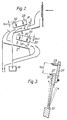
- Figure 2 is a diagrammatic side elevation of the coin selector/rejector assembly,
- Figure 3 is a view in section on the line E-E of Figure 2,
- Figure 4 is a diagrammatic side elevation of the coin accumulator assembly,
- Figure 5 is a view in section on the line G-G of Figure 4,
- Figure 6 is a view in section on the line H-H of Figure 4,
- Figure 7 is a view in section on the line F-F of Figure 4,
- Figure 8 is a diagram of the coin sensor assembly and encash/refund mechanism, and
- Figure 9 is a diagram of detail of a dispensing drawer.
- The flow diagram of Figure 1 shows the general sequence of events following insertion of a coin into the dispenser. It should be noted that at all times the user's money is "safe", i.e. all accumulated coins are retrievable, prior to the successful operation of either drawer, by pressing the coin return button.
- After a coin is inserted, as at 1, a test is performed at a
first gate 2 to determine if the coin diameter equals a first preset diameter x. If the answer is "yes" the coin is routed in the direction of afirst accumulator 17 for coins of diameter x. If the coin diameter is too small the coin is ejected for return to the user at arefund cup 16. If the coin is too big it passes for test at a second gate 3 to determine if the coin diameter equals a second and larger preset diameter y. If the answer is "yes" the coin is routed in the direction of asecond accumulator 18 for coins of diameter y. If the coin is too small or too big it is rejected to therefund cup 16. Coins of diameter x en route to theaccumulator 17 are subjected at 5 to a thickness test; if a coin is too thick it is rejected to the refund cup. Coins of diameter y en route to theaccumulator 18 are likewise subjected at 4 to a thickness test and coins that are too thick rejected to the refund cup. Coins of diameters x and y that pass the thickness test are stacked in theaccumulators - At any time before a drawer is pulled, the user can obtain return of the coins stacked in the
accumulators coin return button 6. If the left-hand drawer 7 is pulled, the right-hand drawer 8 is locked, and vice versa, and if either drawer is pulled thecoin return button 6 is disabled. Before a drawer is released, both thesensor 9 of theaccumulator 17 and thesensor 10 of theaccumulator 18 must be registering the presence of the required tally of coins in the respective accumulator. If either sensor is not registering the required tally, the drawers remain locked, as at 11 or 12. When a drawer has been released and pulled, as at 13, all the coins stacked in the accumulators pass into the coinboxes of the machine, as at 14. The operating cycle is completed by automatic re-locking of the drawer, at 15, when the drawer is returned after removal of the dispensed packet. - The coin selector/rejector assembly will now be described with reference to Figures 2 and 3.
- In this device each coin rolls on
bottom rails 21 past one or both "gates" 2, 3, whose top-rail height, defined byrespective plates 19, 20, is accurately adjustable within a preset range (15-30 mm). Each gate selects coins within a specified diameter tolerance band (X±0.35 mm or Y±0.35 mm) for accumulation. Selected coins S fit between the top and bottom rails, undersize coins R fall through, and oversize coins P cannot fit beneath the top rail. - Each
gate top plate 19 or 20 carries twolocation pins 22 which, in conjunction with a respective pair ofpins 23 on themain structure 24 of the selector/rejector, allow accurate positioning of theplates 19, 20 by accurate setting of the pin centre lines dimension "D", without recourse to trial and error methods with coins. These settings are made by using pre-drilled templates unique to each particular coin type, which templates are removable parts of the accumulator assembly, in that they also serve as coin gauge plates in the respective accumulator columns. Thus, in the event of a need to change the device from operating on coin types A and B to coin types A and C, the total part change requirement is limited to a single coin gauge plate exchange-the new plate also serving to allow accurate re-adjustment of the respective gate dimension "D" so as to select coins of type C. - Each
gate 2, 3 is, in effect, a pair of associated diameter sensing elements offering triple choice of the result (oversize or correct size or undersize) in a single coin pass, rather than the normal dual choice (oversize or undersize). This considerably simplifies the task of selecting two differing coin diameters from all those inserted into the unit. - The coin accumulator unit is shown in Figures 4 to 7.
- This device accepts coins of one or two diameter sizes arriving through two separate chutes from the selector/rejector assembly mounted above it, and stacks them in two
vertical columns coins 27 rest edge-on-edge with their rims presented for detection by the adjacent coin sensor assembly. The column widths are set at approximately 1.25xcoin thickness in each case, there beingface plates accumulator body 28 each of which defines with the body 28 aslot face plate top portion 35 cranked outwards to form a coin chute (Figure 7). - The horizontal dimension of each
column coin gauge plate respective face plate accumulator body 28, it also determines, by its thickness, the width of therespective coin slot slot coin check bar 33 set into theaccumulator body 28 at the throat of the coin chute defined between the accumulator body and the crankedportion 35 of therespective face plate reject chute 36 adjacent the accumulator body and common to both columns. Thus any coin selected for correct diameter but over-size as regards thickness is not able to block the top of the respective accumulator coin column but is rejected and returned to the user. - The coin sensor assembly is shown in Figure 8.
- This assembly comprises two pairs of sensing
fingers 37, 38, one pair for each coin column, carried on pivotally-mountedarms 39, 40. The right hand arms of each pair are connected bylinks 41 tosears 46 cooperating with acam profile 42 on theleft hand drawer 7, and the left hand arms are likewise connected bylinks 43 to sears 47 cooperating with acam profile 44 on theright hand drawer 8. Each pair of arms has atension spring 45 pulling the arms toward one another. When the drawers are fully home, thefingers 37, 38 on thearms 39, 40 are held out away from the coin columns in theslots drawer cam profile coins 27 and the drawer is released. But if only one of the columns does not contain enough coins, the respective finger and arm will not be arrested, as a consequence of which at least one of the twosears 46 or 47 appertaining to that drawer will fully enter arecess 48 or 49 in the drawer and lock it against further movement. Assuming, however, the drawer is released, thesears 46 or 47 will only effect slight entry into therecess 48 or 49 and will then be cammed out again by aprofile fingers 37, 38 to the rest position out of contact with thecoins 27 so that they will not interfere with subsequent dropping of the coins into the coin boxes. - Should drawer release be required without a coin tally in either or both columns for either or both drawers, positioning the relevant coin sensor(s) 37/38 at the extreme top detented position of their travel causes the sensor(s) to abut a flange on the sensor mechanism chassis which prevents inward movement of the sensor(s), the result being as if the presence of a coin has been correctly sensed.
- The encash/reject system for the coins is also shown in Figure 8.
- A further drawer cam/sear arrangement comprises two opposed abutting
bars spring 92, and a freely slidable sear-endedinterlock bar 90 which cooperates at one end with arecess 54 andcam profile 55 of the left-hand drawer 7, and at the other with arecess 56 andcam profile 57 of the right-hand drawer 8. If one drawer is pulled theinterlock bar 90 is cammed in the direction of the other drawer by thecam profile end 91 into itsrecess interlock bar 90 to slide laterally to achieve its locking task on the opposing drawer through the action of theinitial cam profile shoulder 93 on the interlock bar into contact with an opposingshoulder 94 on thebar parallel section 58 of the cam profile on the drawer to be pulled past the interlock sear 91, after which asecond cam 95 causes further lateral movement of the interlock bar and consequently of thebars shoulders - The
coins 27 in the twoaccumulator slots bars bars flaps 59 are caused to swing inward whereby the coins in both accumulator columns are allowed to fall and are directed by theflaps 59 outward into themachine coin boxes 63. - When the
bars refund button 64 at the front of the machine can be pushed inward against the action of acompression spring 65, whereupon inwardly directedcam fingers 66 on the refund button engagepins 67 on thebars spring 92. This causes thebars interlock bar 90 to remain in a centred position, by reason of engagement of theshoulders flaps 59 into acentral chute 68 that delivers them to therefund cup 16. However, when a drawer is pulled, thepins 67 on thebars cam fingers 66 and so therefund button 64 is then temporarily disabled. - Each drawer has a return spring 69 and a two- way ratchet mechanism that is disengaged both when the drawer is fully home and when it is pulled right out but runs into engagement soon after opening or closing movement of the drawer is commenced. This mechanism comprises a
rack 96 with triangular teeth on the drawer, and a cooperating square-nosed pawl 97 pivoted on the machine frame and having aspring 98 keeping it in a centred or neutral position when it is out of engagement with the rack teeth. Following successful completion of the coin-sensing operation, the ratchet commences to operate on the moving drawer so that return of the drawer is positively prevented until nearly full extension of the drawer is achieved. Return of the drawer is similarly controlled, re-extension being prevented once the ratchet is re-engaged, so that only inward motion of the drawer is possible right up to the reengagement of the coin sensing latches, just before achieving the "home" position for the drawer. - Figure 9 shows detail of a
drawer - A thin substantially horizontal
rectangular flap 70 lies in a recess 71 in the bottom of each drawer near the back end of the drawer and is hinged at its rear edge, at 72, the hinge axis extending horizontally across the drawer. Theflap 70 is lightly spring-loaded by aspring 73 which, if the drawer is empty, urges the flap up out of the recess 71 into a position in which thefront edge 74 of the flap is raised to the level of the tops of the drawer sides 75. Two hookedextensions 76 on the rear of theflap 70 behind the hinge line project downwards throughholes 77 in the drawer bottom and, when the flap rises under the spring force acting on it, thehooks 76 are lowered, to engage with rearwardly and upwardly directedprojections 78 pressed up from the metal of the fixedchassis 79 of the dispenser if an attempt is made to pull out the empty drawer. By this means the drawer is locked when empty. When apacket 96 to be vended is contained in the drawer, the flap lies flat in the bottom of the drawer under the weight of the packet and thehooks 76 are raised clear of theprojections 78 so that they do not prevent pulling out of the drawer. - In this way, pulling out of a drawer is positively prevented if there are no packets to vend. Furthermore, when a full drawer is pulled out and the
packet 96 therein removed, the spring-loadedflap 70 will immediately rise and seal off the rear part of the drawer space and the interior of the dispenser above the drawer, thus greatly reducing the possibility of theft of or tampering with the packets still in the dispenser above the drawer through the drawer aperture. A leaf spring 80 attached to thechassis 79 under the drawer is arranged to engage a downward protuberance 81 on theflap 70 just forward of thehinge 72 so as to considerably increase the upward spring force on the flap during the final part of drawer outward travel. This proffers the packet being vended to the customer and also improves the anti-theft feature, without compromising the lightness of the initial spring force of thespring 73, thereby ensuring that the weight of a single packet can depress theflap 70 when the drawer is in its usual position retracted inside the machine.
Claims (13)
Priority Applications (4)
| Application Number | Priority Date | Filing Date | Title |
|---|---|---|---|
| GB08400937A GB2133911B (en) | 1983-01-17 | 1984-01-13 | Coin-freed vending machine mechanism |
| EP19840305071 EP0169281B1 (en) | 1983-01-17 | 1984-07-25 | Coin-freed vending machine mechanism |
| DE8484305071T DE3481094D1 (en) | 1984-07-25 | 1984-07-25 | MECHANISM FOR COIN-ACTUATED SALES MACHINES. |
| AT84305071T ATE49667T1 (en) | 1984-07-25 | 1984-07-25 | MECHANISM FOR COIN-OPERATED VENDING MACHINES. |
Applications Claiming Priority (3)
| Application Number | Priority Date | Filing Date | Title |
|---|---|---|---|
| GB838301139A GB8301139D0 (en) | 1983-01-17 | 1983-01-17 | Coin-freed vending machine mechanism |
| GB08400937A GB2133911B (en) | 1983-01-17 | 1984-01-13 | Coin-freed vending machine mechanism |
| EP19840305071 EP0169281B1 (en) | 1983-01-17 | 1984-07-25 | Coin-freed vending machine mechanism |
Publications (2)
| Publication Number | Publication Date |
|---|---|
| EP0169281A1 EP0169281A1 (en) | 1986-01-29 |
| EP0169281B1 true EP0169281B1 (en) | 1990-01-17 |
Family
ID=27227205
Family Applications (1)
| Application Number | Title | Priority Date | Filing Date |
|---|---|---|---|
| EP19840305071 Expired EP0169281B1 (en) | 1983-01-17 | 1984-07-25 | Coin-freed vending machine mechanism |
Country Status (2)
| Country | Link |
|---|---|
| EP (1) | EP0169281B1 (en) |
| GB (1) | GB2133911B (en) |
Families Citing this family (3)
| Publication number | Priority date | Publication date | Assignee | Title |
|---|---|---|---|---|
| GB2133911B (en) * | 1983-01-17 | 1986-06-04 | Self Serve Hygiene Ltd | Coin-freed vending machine mechanism |
| US4987989A (en) * | 1989-07-24 | 1991-01-29 | Buckenham Nicholas H | Coin-freed vending machine mechanism |
| JP7598918B2 (en) * | 2022-12-23 | 2024-12-12 | 株式会社バンダイ | Item supply device |
Family Cites Families (12)
| Publication number | Priority date | Publication date | Assignee | Title |
|---|---|---|---|---|
| GB302218A (en) * | 1927-12-12 | 1928-12-10 | Fritz Eller | Improvements in coin controlled sales apparatus |
| GB336281A (en) * | 1929-06-27 | 1930-10-10 | Fritz Eller | Improvements in coin-freed sales apparatus |
| GB534099A (en) * | 1938-12-13 | 1941-02-27 | Parnall & Sons Ltd | Automatic vending machine |
| GB753266A (en) * | 1953-04-25 | 1956-07-18 | Soren Wistoft & Co S Fabriker | Improvements in and relating to coin releases for vending machines |
| GB1127277A (en) * | 1967-03-17 | 1968-09-18 | Coombe Products Furniture Ltd | Coin released mechanism |
| GB1194703A (en) * | 1967-05-10 | 1970-06-10 | Coombe Products Furniture Ltd | Coin Released Mechanism |
| IE33145B1 (en) * | 1969-06-04 | 1974-04-03 | Kenson Ltd | Coin released mechanism |
| DE2724480A1 (en) * | 1977-05-31 | 1978-12-14 | Herbert Kneip | Automatic vending machine selective coin transport mechanism - has push-rod carrying coin shaft housing and actuated by esp. cigarette withdrawal drawer and coin sensor arrangement |
| GB2007416B (en) * | 1977-08-23 | 1982-01-13 | Mayfair Cigarette Co Ltd | Coin totalizer for vending machines |
| GB2022898B (en) * | 1978-05-10 | 1982-06-23 | Mayfair Cigarette Co Ltd | Coin operated vending machine |
| DE3101579A1 (en) * | 1981-01-20 | 1982-08-26 | Hollmann Gmbh & Co, 4800 Bielefeld | Vending machine |
| GB2133911B (en) * | 1983-01-17 | 1986-06-04 | Self Serve Hygiene Ltd | Coin-freed vending machine mechanism |
-
1984
- 1984-01-13 GB GB08400937A patent/GB2133911B/en not_active Expired
- 1984-07-25 EP EP19840305071 patent/EP0169281B1/en not_active Expired
Also Published As
| Publication number | Publication date |
|---|---|
| GB8400937D0 (en) | 1984-02-15 |
| GB2133911A (en) | 1984-08-01 |
| GB2133911B (en) | 1986-06-04 |
| EP0169281A1 (en) | 1986-01-29 |
Similar Documents
| Publication | Publication Date | Title |
|---|---|---|
| US8109379B2 (en) | Coin deposit and dispensing apparatus | |
| CA1051309A (en) | Coin apparatus having multiple coin-diverting gates | |
| US4412607A (en) | Vending machine with improved means for dispensing products at a predetermined price | |
| US4966304A (en) | Bill money changer for slot machines | |
| US2681842A (en) | Multiple magazine type article vending apparatus | |
| US5492212A (en) | Device for sorting and storing objects inserted by way of payment in a dispenser | |
| US3948377A (en) | Coin handling apparatus for a vending machine | |
| US2037462A (en) | Coin controlled mechanism | |
| US4987989A (en) | Coin-freed vending machine mechanism | |
| EP0169281A1 (en) | Coin-freed vending machine mechanism | |
| JP3926956B2 (en) | Coin processing equipment | |
| US3464530A (en) | Coin controlled vending mechanism utilizing a plurality of coins of different denominations | |
| US2283252A (en) | Coin-operated vending machine and control mechanism therefor | |
| US1788523A (en) | Vending machine | |
| US3613855A (en) | Coin controlled lock for two coins | |
| US2894612A (en) | Dispensing machine | |
| US3169621A (en) | Selective bottle vending machine | |
| US4399902A (en) | Coin-handling escrow assembly | |
| US1334299A (en) | Paper-vending machine | |
| US2087787A (en) | Fare collector | |
| US3709347A (en) | Bag vending machine having feeler controlled lock | |
| JP7835319B1 (en) | Money processing system and money processing device | |
| US2858921A (en) | Coin apparatus | |
| US2934192A (en) | Coin control mechanism for vending machines | |
| US3666068A (en) | Coin released mechanism in a vending machine |
Legal Events
| Date | Code | Title | Description |
|---|---|---|---|
| PUAI | Public reference made under article 153(3) epc to a published international application that has entered the european phase |
Free format text: ORIGINAL CODE: 0009012 |
|
| AK | Designated contracting states |
Designated state(s): AT BE CH DE FR IT LI LU NL SE |
|
| 17P | Request for examination filed |
Effective date: 19860723 |
|
| 17Q | First examination report despatched |
Effective date: 19871120 |
|
| GRAA | (expected) grant |
Free format text: ORIGINAL CODE: 0009210 |
|
| AK | Designated contracting states |
Kind code of ref document: B1 Designated state(s): AT BE CH DE FR IT LI LU NL SE |
|
| PG25 | Lapsed in a contracting state [announced via postgrant information from national office to epo] |
Ref country code: AT Effective date: 19900117 |
|
| REF | Corresponds to: |
Ref document number: 49667 Country of ref document: AT Date of ref document: 19900215 Kind code of ref document: T |
|
| REF | Corresponds to: |
Ref document number: 3481094 Country of ref document: DE Date of ref document: 19900222 |
|
| ITF | It: translation for a ep patent filed | ||
| ET | Fr: translation filed | ||
| PLBE | No opposition filed within time limit |
Free format text: ORIGINAL CODE: 0009261 |
|
| STAA | Information on the status of an ep patent application or granted ep patent |
Free format text: STATUS: NO OPPOSITION FILED WITHIN TIME LIMIT |
|
| 26N | No opposition filed | ||
| ITTA | It: last paid annual fee | ||
| EPTA | Lu: last paid annual fee | ||
| EAL | Se: european patent in force in sweden |
Ref document number: 84305071.7 |
|
| REG | Reference to a national code |
Ref country code: CH Ref legal event code: PFA Free format text: SELF SERVE HYGIENE LIMITED TRANSFER- SELF SERVE LIMITED |
|
| NLT1 | Nl: modifications of names registered in virtue of documents presented to the patent office pursuant to art. 16 a, paragraph 1 |
Owner name: SELF SERVE LIMITED |
|
| REG | Reference to a national code |
Ref country code: FR Ref legal event code: CD |
|
| PGFP | Annual fee paid to national office [announced via postgrant information from national office to epo] |
Ref country code: SE Payment date: 20010704 Year of fee payment: 18 |
|
| PGFP | Annual fee paid to national office [announced via postgrant information from national office to epo] |
Ref country code: FR Payment date: 20010712 Year of fee payment: 18 |
|
| PGFP | Annual fee paid to national office [announced via postgrant information from national office to epo] |
Ref country code: DE Payment date: 20010716 Year of fee payment: 18 |
|
| PGFP | Annual fee paid to national office [announced via postgrant information from national office to epo] |
Ref country code: LU Payment date: 20010719 Year of fee payment: 18 |
|
| PGFP | Annual fee paid to national office [announced via postgrant information from national office to epo] |
Ref country code: NL Payment date: 20010730 Year of fee payment: 18 Ref country code: CH Payment date: 20010730 Year of fee payment: 18 |
|
| PGFP | Annual fee paid to national office [announced via postgrant information from national office to epo] |
Ref country code: BE Payment date: 20010918 Year of fee payment: 18 |
|
| PG25 | Lapsed in a contracting state [announced via postgrant information from national office to epo] |
Ref country code: LU Free format text: LAPSE BECAUSE OF NON-PAYMENT OF DUE FEES Effective date: 20020725 |
|
| PG25 | Lapsed in a contracting state [announced via postgrant information from national office to epo] |
Ref country code: SE Free format text: LAPSE BECAUSE OF NON-PAYMENT OF DUE FEES Effective date: 20020726 |
|
| PG25 | Lapsed in a contracting state [announced via postgrant information from national office to epo] |
Ref country code: LI Free format text: LAPSE BECAUSE OF NON-PAYMENT OF DUE FEES Effective date: 20020731 Ref country code: CH Free format text: LAPSE BECAUSE OF NON-PAYMENT OF DUE FEES Effective date: 20020731 Ref country code: BE Free format text: LAPSE BECAUSE OF NON-PAYMENT OF DUE FEES Effective date: 20020731 |
|
| BERE | Be: lapsed |
Owner name: *SELF SERVE LTD Effective date: 20020731 |
|
| PG25 | Lapsed in a contracting state [announced via postgrant information from national office to epo] |
Ref country code: NL Free format text: LAPSE BECAUSE OF NON-PAYMENT OF DUE FEES Effective date: 20030201 Ref country code: DE Free format text: LAPSE BECAUSE OF NON-PAYMENT OF DUE FEES Effective date: 20030201 |
|
| EUG | Se: european patent has lapsed | ||
| REG | Reference to a national code |
Ref country code: CH Ref legal event code: PL |
|
| PG25 | Lapsed in a contracting state [announced via postgrant information from national office to epo] |
Ref country code: FR Free format text: LAPSE BECAUSE OF NON-PAYMENT OF DUE FEES Effective date: 20030331 |
|
| NLV4 | Nl: lapsed or anulled due to non-payment of the annual fee |
Effective date: 20030201 |
|
| REG | Reference to a national code |
Ref country code: FR Ref legal event code: ST |