EP0169189B2 - Linear measuring system - Google Patents
Linear measuring system Download PDFInfo
- Publication number
- EP0169189B2 EP0169189B2 EP85890150A EP85890150A EP0169189B2 EP 0169189 B2 EP0169189 B2 EP 0169189B2 EP 85890150 A EP85890150 A EP 85890150A EP 85890150 A EP85890150 A EP 85890150A EP 0169189 B2 EP0169189 B2 EP 0169189B2
- Authority
- EP
- European Patent Office
- Prior art keywords
- strip
- housing tube
- scanning unit
- metal strip
- scanning
- Prior art date
- Legal status (The legal status is an assumption and is not a legal conclusion. Google has not performed a legal analysis and makes no representation as to the accuracy of the status listed.)
- Expired - Lifetime
Links
Images

Classifications
-
- G—PHYSICS
- G01—MEASURING; TESTING
- G01B—MEASURING LENGTH, THICKNESS OR SIMILAR LINEAR DIMENSIONS; MEASURING ANGLES; MEASURING AREAS; MEASURING IRREGULARITIES OF SURFACES OR CONTOURS
- G01B5/00—Measuring arrangements characterised by the use of mechanical techniques
- G01B5/0011—Arrangements for eliminating or compensation of measuring errors due to temperature or weight
- G01B5/0014—Arrangements for eliminating or compensation of measuring errors due to temperature or weight due to temperature
Landscapes
- Physics & Mathematics (AREA)
- General Physics & Mathematics (AREA)
- Length Measuring Devices With Unspecified Measuring Means (AREA)
- Analysing Materials By The Use Of Radiation (AREA)
- Signal Processing For Digital Recording And Reproducing (AREA)
- Photoreceptors In Electrophotography (AREA)
- Length Measuring Devices By Optical Means (AREA)
Abstract
Description
Die Erfindung betrifft ein lineares Meßsystem nach dem Oberbegriff des Patentanspruches 1.The invention relates to a linear measuring system according to the preamble of
Ein derartiges Meßsystem istausderEP-A-0 105 119 bekannt.Such a measuring system is known from EP-A-0 105 119.
Allgemein kann bei derartigen Meßsystemen der Maßstab entweder in Form einer meist mehrspurigen codierten Spur für absolute Meßsysteme oder in Form einer Inkrementalteilung für inkrementale Meßsysteme vorgesehen sein, wobei neben der Inkrementalteilung ein oder mehrere Spuren für Referenzmarken angebracht werden können. Die Abtastung der jeweiligen Maßstabverkörperung über die Abtasteinheit erfolgt nach optoelektronischen, induktiven, magnetischen oder kapazitiven Abtastprinzipien. In allen Fällen werden elektrische Abtastsignale erhalten, die meist nach Umformung in Digitalsignale, weiterverarbeitet und für die Meßanzeige bzw. in einer Maschinensteuerung ausgenützt werden. Der Hohlprofilbalken wird im Normalfall an einer Werkzeugmaschine oder in einem Industrieroboter befestigt und die Abstateinheitwird mit einem bewegbaren Teil, dessen Lageveränderung zu messen ist, verbunden oder umgekehrt. Dabei wird meist ein an der Unterseite geschlitzter Hohlprofil-Balken verwendet, in dem die Abtasteinheit der Länge nach verstellbar ist, wobei für die Verstellung der Abtasteinheit ein zwischen den Spalt abdichtenden Dichtlippen herausgeführtes Schwert dient.In general, with such measuring systems, the scale can be provided either in the form of a mostly multi-track coded track for absolute measuring systems or in the form of an incremental graduation for incremental measuring systems, one or more tracks for reference marks being able to be attached in addition to the incremental graduation. The respective scale embodiment is scanned via the scanning unit according to optoelectronic, inductive, magnetic or capacitive scanning principles. In all cases, electrical scanning signals are obtained, which are usually further processed after being converted into digital signals and used for the measurement display or in a machine control. The hollow section beam is normally attached to a machine tool or in an industrial robot and the removal unit is connected to a movable part whose change in position is to be measured, or vice versa. In this case, a hollow profile bar slotted on the underside is usually used, in which the scanning unit can be adjusted in length, a sword extending between the gap serving sealing lips serving for the adjustment of the scanning unit.
Nach der EP-A-0 105 119 nimmt der Hohlprofil- Balken als rohrförmiger Längstragereine Trägerfunktion wahr und trägt die Abtasteinheit. Die auf das eine Ende wirkende Federanordnung stützt sich an einem unmittelbar auf das Ende des Hohlprofil-Balkens aufgesetzten Tragstück ab und für das herausgeführte Ende des Bandes dient ein über Spannschrauben ebenfalls am Hohlprofil-Balken abgestütztes Spannstück. Die Abtasteinheit besitzt eine an der Unterseite des Bandes angreifende Führungsplatte, die mit einer Nut zur Aufnahme des Bandes versehen ist und somit das Band gegenüber der Abtasteinheit führt. Ferner ist die Abtasteinheit mit seitlich vorstehenden Führungsstücken in seitlichen Längsnuten des Hohlprofil-Balkens geführt, so daß die Abtasteinheit, die mit einem Mitnehmer über ein nachgiebiges Zwischenstück verbunden ist, bei der Abtastung des Maßstabes jeweils genau dem Verlauf des Hohlprofil-Balkens folgt und auch das Band entsprechend diesem Verlauf einstellt.According to EP-A-0 105 119, the hollow profile bar, as a tubular longitudinal beam, performs a carrier function and carries the scanning unit. The spring arrangement acting on one end is supported on a support piece placed directly on the end of the hollow profile bar and a tensioning piece also supported on the hollow profile bar by means of tensioning screws is used for the lead-out end of the band. The scanning unit has a guide plate which engages on the underside of the belt, which is provided with a groove for receiving the belt and thus guides the belt opposite the scanning unit. Furthermore, the scanning unit is guided with laterally projecting guide pieces in the lateral longitudinal grooves of the hollow profile bar, so that the scanning unit, which is connected to a driver via a flexible intermediate piece, exactly follows the course of the hollow profile bar when scanning the scale and also that Band adjusts according to this course.
Aus der US-A-4 117 439 ist ein für induktive Abtastung bestimmtes Meßsystem bekannt, bei dem ein die Maßstabwindungen tragendes Band zwischen zwei am Maschinenkörper befestigbaren Halteböcken gespannt ist und unter starrer Einspannung durch Festklemmung der Bandenden unter einer Vorspannung gehalten werden kann, die sich allerdings bei relativ unterschiedlichen Wärmedehnungen von Band und Maschinenkörper ändert. Die eine Spule aufweisende Abtasteinheit ist mit Führungselementen für das Band versehen, die eine an der von der Spule abweisenden Seite gegen das Band durch Federn angedrückte Führungsplatte und Randhalter für das Band umfassen, gegen die das Band durch die Federn gedrückt wird. Das Band mit der Abtasteinheit kann nach unten hin durch eine Schutzplatte abgedeckt werden, die entweder am Maschinengehäuse oder an den Halteböcken für das Band befestigt wird. Bei Ausbildung der Schutzplatte als Winkel profil kann sie durch weitere angesetzte Profile zu einem einseitig offenen Gehäuse ergänzt werden, wobei die Abtasteinheit an einem durch die Gehäuseöffnung einragenden Arm gehalten wird.From US-A-4 117 439 a measuring system intended for inductive scanning is known, in which a tape carrying the scale windings is stretched between two mounting brackets which can be fastened to the machine body and can be held under rigid tension by clamping the tape ends under a pre-tension which is however, with relatively different thermal expansions of the belt and machine body changes. The scanning unit having a spool is provided with guide elements for the band, which comprise a guide plate pressed against the band by springs on the side facing away from the spool and edge holders for the band, against which the band is pressed by the springs. The tape with the scanning unit can be covered at the bottom by a protective plate, which is either attached to the machine housing or to the support stands for the tape. When the protective plate is designed as an angle profile, it can be supplemented by further profiles to form a housing open on one side, the scanning unit being held on an arm protruding through the housing opening.
Bei einem Meßsystem nach der US-A-38 16 002 sind die Enden des hier wieder eine Trägerfunktion erfüllenden Hohlprofil-Balkens durch Deckel abgeschlossen, an denen die Enden des Maßstabes gehalten sind. Das eine Maßstabende wird mit Hilfe eines Spannbockes fest eingespannt. Das andere Maßstabende wird im Schlitz eines über eine Schraube der Länge nach verstellbaren Bolzens gehalten, wobei eine zusätzliche Feder vorgesehen ist, die das Bestreben hat, den Bolzen im Sinne einer Spannung des Maßstabbandes zu verstellen. Die Federvorspannung ist mittels der Schraube einstellbar. Dabei gibt es Konstruktionen, bei denen die Schraube im Inneren des Hohlprofil-Balkens untergebracht ist. Andere Konstruktionen verwenden eine oder mehrere von außen betätigbare Spannschrauben.In a measuring system according to US-A-38 16 002, the ends of the hollow profile bar again fulfilling a carrier function here are closed off by covers, on which the ends of the scale are held. One end of the scale is firmly clamped with the help of a clamp. The other end of the scale is held in the slot of a bolt which can be adjusted in length by means of a screw, an additional spring being provided which tends to adjust the bolt in the sense of tensioning the scale band. The spring preload can be adjusted using the screw. There are constructions in which the screw is housed inside the hollow profile beam. Other constructions use one or more externally operated tension screws.
Die Hohlprofil-Balken werden wegen der leichten Herstellbarkeit fast ausschließlich aus Leichtmetall, insbesondere Aluminium hergestellt. Dieses besitzt gegenüber dem Material des Maschinenbettes, an dem der Hohlprofil-Balken befestigt wird, einen wesentlich größeren Ausdehnungskoeffizienten. Die Längenänderung des Hohlprofil-Balkens mit der Temperatur bewirkt Spannungsänderungen im Metallband und damit stärkere Längenänderungen als das Band aufgrund seines gegenüber Aluminium geringeren Ausdehnungskoeffizienten durch die Temperatur erleiden würde. Ein Stahlband hätte an sich etwa den gleichen Ausdehnungskoeffizienten wie das aus Stahl hergestellte Maschinenbett. Die durch die verschiedenen Wärmedehnungen und insbesondere die starke Wärmedehung des Hohlprofil-Balkens bedingten Spannungsänderungen können zu Abtast- und Meßfehlern führen. Dies gilt insbesondere für längere Meßsysteme.The hollow profile beams are almost exclusively made of light metal, in particular aluminum, because of their ease of manufacture. Compared to the material of the machine bed to which the hollow section beam is attached, this has a much larger expansion coefficient. The change in length of the hollow profile bar with temperature causes changes in tension in the metal strip and thus more changes in length than the strip would suffer due to its lower expansion coefficient compared to aluminum due to the temperature. A steel band would have about the same expansion coefficient as the machine bed made of steel. The voltage changes caused by the different thermal expansions and in particular the strong thermal expansion of the hollow profile beam can lead to scanning and measuring errors. This applies in particular to longer measuring systems.
Bei einer bekannten Konstruktion wird das Metallband in eine Nut des Hohlprofil-Balkens eingebettet und in dieser Nut durch eine elastisch nachgiebige Klebung oder sonstige Halterung befestigt. Bei dieser Ausführung ist zwar eine Spanneinrichtung vorgesehen, doch kann diese besonders beim längeren Band nur zum Teil und oft nicht über die ganze Bandlänge wirksam werden. Vor allem ergeben sich wegen der Haftung des Bandes an der Bettung über die Länge unterschiedliche Spannkräfte und dadurch unterschiedliche Dehnungen. Das Band folgt wegen der Bettung Unlinearitäten des Trägers. Die Abtasteinheit wird bei der beschriebenen Ausführung meist in Form eines Wägelchens ausgebildet, das auf dem wie erwähnt abgestützten Band geführt ist. Es können sich bei der Abtastung zwischen dem ablesenden Teil der Abtasteinheit und dem am Band vorgesehenen Maßstab Abstandsänderungen sowohl quer zur Bandhauptebene als auch Verschiebungen in der Bandebene, insbesondere zu den Seiten des Bandes hin, ergeben, was zu Signaländerungen und Meßfehlern führen kann. Die erwähnten Verlagerungen können überdies bei aufeinanderfolgenden Abtastvorgängen an der gleichen Maßstabstelle in unterschiedlicher Weise erfolgen, so daß auch allenfalls vorgesehene Korrektureinrichtungen, die die erwähnten Fehler durch gespeicherte Korrektursignale ausgleichen sollen, wenigstens zum Teil unwirksam werden.In a known construction, the metal strip is embedded in a groove of the hollow profile beam and fastened in this groove by an elastically flexible adhesive or other holder. In this embodiment, a tensioning device is provided, but this can be effective only partially and often not over the entire length of the tape, particularly in the case of the longer tape. Above all because of the Adhesion of the tape to the bedding along the length different tension forces and thus different strains. The tape follows nonlinearities of the wearer because of the bedding. In the embodiment described, the scanning unit is usually designed in the form of a carriage which is guided on the belt supported as mentioned. During the scanning between the reading part of the scanning unit and the scale provided on the tape, changes in distance can occur both transversely to the main tape level and shifts in the tape plane, in particular to the sides of the tape, which can lead to signal changes and measurement errors. The above-mentioned displacements can moreover take place in successive scanning processes at the same scale position in different ways, so that any correction devices which are provided and which are intended to compensate for the errors mentioned by stored correction signals become at least partially ineffective.
Aufgabe der Erfindung ist die Schaffung eines linearen Meßsystemes der genannten Art, bei dem mit einfachen Mitteln eine Auswirkung der von Maschinenbett unterschiedlichen temperaturabhängigen Lageänderungen des Hohlprofil-Balkens auf die Abtastung ebenso vermieden werden, wie nachteilige Auswirkungen eines ungeraden Verlaufes des Hohlprofil-Balkens auf die Abtastung.The object of the invention is to provide a linear measuring system of the type mentioned, in which an effect of the temperature-dependent changes in position of the hollow profile bar different from the machine bed on the scanning are avoided, as well as disadvantageous effects of an odd profile of the hollow profile bar on the scanning .
Die gestellte Ausgabe wird durch die Merkmale des Patentanspruches 1 gelöst.The issue is solved by the features of
Durch die im Nachhinein äußerst einfach erscheinende erfindungsgemäße Maßnahme, können sich, da der Hohlprofil-Balken keine entscheidende Trägerfunktion mehr hat und sich die die Enden des Bandes haltenden Elemente nicht an ihm abstützen, auch stärkere Längenänderungen dieses Hohlprofil-Balkens nicht mehr zu Änderungen der Längsspannungen auswirken. Da das Band frei gespannt ist, wirkt sich auch ein ungerader Verlauf des Hohlprofil-Balkens nicht aus. Das Band unterliegt in jedem Bereich seiner Länge der gleichen Zugspannung Bei der Abtastung ist die Relativlage von Abtasteinheit und Band quer zur Bandlängsrichtung, und zwar sowohl in der Bandebene als auch normal dazu festgelegt, so daß die Abtastegenauigkeit erhöht wird und gegenüber der bekannten Ausführung gleichmäßigere Signale erhalten werden. Die Bandenden sind leicht zugänglich und es ergibt sich eine einfache Spannvorrichtung.As a result of the measure according to the invention, which appears extremely simple in retrospect, since the hollow profile beam no longer has a decisive support function and the elements holding the ends of the band are not supported on it, even greater changes in length of this hollow profile beam can no longer lead to changes in the longitudinal stresses impact. Since the belt is freely tensioned, an uneven course of the hollow profile beam has no effect. The tape is subject to the same tensile stress in every area of its length. When scanning, the relative position of the scanning unit and tape is determined transversely to the tape longitudinal direction, both in the tape plane and normal to it, so that the scanning accuracy is increased and signals are more uniform compared to the known design be preserved. The tape ends are easily accessible and there is a simple tensioning device.
Nach einer Weiterbildung ist das eine Bandende über einen Stelltrieb und das andere Bandende uber eine Feder am zugehörigen Spannstück gehalten.According to a further development, one end of the band is held on the associated clamping piece via an actuator and the other end of the band is held by a spring.
In der Zeichnung ist der Erfindungsgegenstand beispielsweise schematisiert dargestellt. Es zeigt
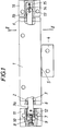
- Fig. 1 ein Meßsystem teilweise in Ansicht und teilweise im Schnitt und
- Fig. 2 einen Schnitt nach der Linie 11-11 der Fig. 1.
- Fig. 1 shows a measuring system partly in view and partly in section and
- 2 shows a section along the line 11-11 of FIG. 1st
Für das Meßsystem ist ein über den Bereich der Meßlänge reichender Hohlprofil-Balken 1 vorgesehen, der in der Zeichnung verkürzt dargestellt wurde. In dem über einen unterseitigen Schlitz, der gegebenenfalls mit Dichtlippen versehen sein kann, zugänglichen Hohlraum 2 des Hohlprofil-Balkens ist ein eine Maßstabverkörperung tragendes Metallband 3 angeordnet, das über eine nur in ihren Umrissen dargestellt Abstasteinheit 17, die über einen mit einem Werkzeugschlitten betätigbaren Halter 4 und ein Schwert 5 verstellbar ist, zur Erzeugung von Meßsignalen abgetastet werden kann.For the measuring system a
Die Enden 3a, 3b des Metallbandes 3 sind durch Schlitze in Enddecken 6 des rohrförmigen Längsträgers 1 herausgeführt. Das Bandende 3a greift in einen Schlitz eines über eine Schraube 8 verstellbaren Spannstückes 9 in einer Bohrung 10 eines Haltestückes 11 ein und ist im Schlitz 7 um eine Querachse 12 schwenkbar.The
Am Bandende 3b greift an einem Querzapfen 13 eine Zugfeder 14 an die ihrerseits wieder in einer Bohrung 15 eines gesondert montierbaren Haltestückes 16 untergebracht ist.At the end of the
Wie insbesondere Fig. 2 zeigt, stützt sich das zwischen den Haltepunkten 12, 13 frei gespannte Maßstabband 3 mit seiner Unterseite frei aufliegend auf einem Steg 18 des Hohlprofil-Balkens 1 ab. Die Abtasteinheit 17 trägt Führungsleisten 19, beispielsweise Kunststoffgleiter, die eine Führung für die Seiten des Maßstabbandes 3 bilden. Weitere Gleiter können eine Abtastplatte oder einen sonstigen zur Abtastung dienenden Teil an der Maßstabseite des Bandes 3 führen.As shown in FIG. 2 in particular, the
Claims (2)
Applications Claiming Priority (2)
| Application Number | Priority Date | Filing Date | Title |
|---|---|---|---|
| AT2317/84 | 1984-07-18 | ||
| AT231784 | 1984-07-18 |
Publications (4)
| Publication Number | Publication Date |
|---|---|
| EP0169189A2 EP0169189A2 (en) | 1986-01-22 |
| EP0169189A3 EP0169189A3 (en) | 1987-06-03 |
| EP0169189B1 EP0169189B1 (en) | 1990-05-23 |
| EP0169189B2 true EP0169189B2 (en) | 1993-08-04 |
Family
ID=3532129
Family Applications (1)
| Application Number | Title | Priority Date | Filing Date |
|---|---|---|---|
| EP85890150A Expired - Lifetime EP0169189B2 (en) | 1984-07-18 | 1985-07-05 | Linear measuring system |
Country Status (4)
| Country | Link |
|---|---|
| US (1) | US4584773A (en) |
| EP (1) | EP0169189B2 (en) |
| AT (1) | ATE53117T1 (en) |
| DE (1) | DE3577910D1 (en) |
Cited By (1)
| Publication number | Priority date | Publication date | Assignee | Title |
|---|---|---|---|---|
| CN102192694A (en) * | 2010-03-18 | 2011-09-21 | 菲高公司 | Optoelectronic measuring device |
Families Citing this family (15)
| Publication number | Priority date | Publication date | Assignee | Title |
|---|---|---|---|---|
| IT1190631B (en) * | 1986-04-22 | 1988-02-16 | G Giacomo Giacomello | TRANSDUCER FOR INCREMENTAL PRECISION MEASUREMENTS OF LINEAR SIZES, WITH COMPENSATION OF THE THERMAL DILATIONS OF THE MEASURING RULES |
| DE3625795A1 (en) * | 1986-07-30 | 1988-02-04 | Heidenhain Gmbh Dr Johannes | LENGTH MEASURING DEVICE |
| DE3719409A1 (en) * | 1987-06-11 | 1988-12-22 | Heidenhain Gmbh Dr Johannes | POSITION MEASURING DEVICE |
| AT393905B (en) * | 1989-09-12 | 1992-01-10 | Rieder Heinz | PROTECTIVE HOUSING FOR RECORDING RULES AND LENGTH ADJUSTABLE SCAN |
| ES2110902B1 (en) * | 1995-07-18 | 1998-08-01 | Fagor S Coop | DEVICE FOR FIXING THE SCALE IN AN OPTICAL RULE. |
| DE19751019C2 (en) * | 1997-11-18 | 2002-11-28 | Heidenhain Gmbh Dr Johannes | A position |
| DE19922363A1 (en) | 1999-05-14 | 2000-11-23 | Rexroth Star Gmbh | Device for determining the relative position of two bodies movable relative to one another and method for producing such a device |
| US6592985B2 (en) * | 2000-09-20 | 2003-07-15 | Camco International (Uk) Limited | Polycrystalline diamond partially depleted of catalyzing material |
| US6639177B2 (en) * | 2001-03-29 | 2003-10-28 | Gsi Lumonics Corporation | Method and system for processing one or more microstructures of a multi-material device |
| US6868620B2 (en) * | 2002-08-01 | 2005-03-22 | Solar Wide Industrial, Ltd. | Digital measuring instrument having flexible measuring line |
| US20060000814A1 (en) * | 2004-06-30 | 2006-01-05 | Bo Gu | Laser-based method and system for processing targeted surface material and article produced thereby |
| DE102004043055B4 (en) | 2004-09-06 | 2009-04-02 | Siemens Ag | Guide device for guiding a movable machine element of a machine |
| EP1731878A1 (en) * | 2005-06-07 | 2006-12-13 | AMO Automatisierung Messtechnik Optik GmbH | Guiding element for machines with compensated length measuring system |
| EP3276310B1 (en) * | 2016-07-27 | 2018-09-19 | Dr. Johannes Heidenhain GmbH | Length measuring device |
| ES2693900T3 (en) * | 2016-08-02 | 2018-12-14 | Dr. Johannes Heidenhain Gmbh | Length measuring device |
Family Cites Families (6)
| Publication number | Priority date | Publication date | Assignee | Title |
|---|---|---|---|---|
| US3816002A (en) * | 1972-10-10 | 1974-06-11 | H Wieg | Apparatus for measuring displacement between two relatively movable members |
| DE2518745C3 (en) * | 1975-04-26 | 1979-06-21 | Dr. Johannes Heidenhain Gmbh, 8225 Traunreut | Error compensation in positioning systems |
| DE2712421C2 (en) * | 1977-03-22 | 1982-06-24 | Dr. Johannes Heidenhain Gmbh, 8225 Traunreut | Encapsulated length measuring device |
| DE2853771C2 (en) * | 1978-12-13 | 1986-08-28 | Dr. Johannes Heidenhain Gmbh, 8225 Traunreut | Length measuring device |
| IT1152526B (en) * | 1982-09-03 | 1987-01-07 | Giacomo Giacomello | METALLIC BELT TRANSDUCES FOR MICROMETRIC MEASUREMENTS OF LINEAR SIZES |
| DE3302151A1 (en) * | 1983-01-22 | 1984-07-26 | Dr. Johannes Heidenhain Gmbh, 8225 Traunreut | LENGTH MEASURING DEVICE |
-
1985
- 1985-07-05 AT AT85890150T patent/ATE53117T1/en not_active IP Right Cessation
- 1985-07-05 DE DE8585890150T patent/DE3577910D1/en not_active Expired - Fee Related
- 1985-07-05 EP EP85890150A patent/EP0169189B2/en not_active Expired - Lifetime
- 1985-07-11 US US06/754,028 patent/US4584773A/en not_active Expired - Fee Related
Cited By (2)
| Publication number | Priority date | Publication date | Assignee | Title |
|---|---|---|---|---|
| CN102192694A (en) * | 2010-03-18 | 2011-09-21 | 菲高公司 | Optoelectronic measuring device |
| CN102192694B (en) * | 2010-03-18 | 2016-01-27 | 菲高公司 | Photoelectric measuring device |
Also Published As
| Publication number | Publication date |
|---|---|
| US4584773A (en) | 1986-04-29 |
| EP0169189B1 (en) | 1990-05-23 |
| EP0169189A3 (en) | 1987-06-03 |
| DE3577910D1 (en) | 1990-06-28 |
| ATE53117T1 (en) | 1990-06-15 |
| EP0169189A2 (en) | 1986-01-22 |
Similar Documents
| Publication | Publication Date | Title |
|---|---|---|
| EP0169189B2 (en) | Linear measuring system | |
| DE2735154C2 (en) | Length or angle measuring system | |
| DE2712421C2 (en) | Encapsulated length measuring device | |
| DE3625795C2 (en) | ||
| DE3243966A1 (en) | LENGTH MEASURING DEVICE | |
| EP0126937B1 (en) | Length measuring device | |
| EP1742023A1 (en) | Linear motion guide with apparatus for measuring the position | |
| EP0709655A2 (en) | Guidance device | |
| EP0513406B1 (en) | Position measuring device | |
| DE69912341T2 (en) | Position sensing device | |
| EP0671606A2 (en) | Position-measuring device | |
| DE69830950T2 (en) | Carrier for a magnetic scale | |
| DE19700367C2 (en) | Method and assembly device for the directed application of a measuring tape | |
| EP0671607B1 (en) | Position-measuring device | |
| EP1731878A1 (en) | Guiding element for machines with compensated length measuring system | |
| DE3208591A1 (en) | LENGTH OR ANGLE MEASURING SYSTEM | |
| EP0681159A1 (en) | Position measuring device with temperature compensation | |
| DE2715843A1 (en) | SIGNAL CONVERTER FOR MEASURING LINEAR POSITIONS | |
| DE10229885B4 (en) | Method and apparatus for attaching a scale or scale carrier or scale guide | |
| DE3434993A1 (en) | Caliper | |
| EP0163857B1 (en) | Position measuring device | |
| EP0075081B1 (en) | Fault compensation device for precision machines and measurement devices | |
| EP0143773B1 (en) | Length-measuringg device, especially an enclosed length-measuring device | |
| DE102007060606A1 (en) | Sensor position's coordinate measuring apparatus, has adjusting unit adjusting position of detector in adjustment direction dependent on temperature, and holder holding detector during position change caused in adjustment direction | |
| DE4318017A1 (en) | Position measuring device |
Legal Events
| Date | Code | Title | Description |
|---|---|---|---|
| PUAI | Public reference made under article 153(3) epc to a published international application that has entered the european phase |
Free format text: ORIGINAL CODE: 0009012 |
|
| AK | Designated contracting states |
Designated state(s): AT BE CH DE FR GB IT LI LU NL SE |
|
| PUAL | Search report despatched |
Free format text: ORIGINAL CODE: 0009013 |
|
| AK | Designated contracting states |
Kind code of ref document: A3 Designated state(s): AT BE CH DE FR GB IT LI LU NL SE |
|
| 17P | Request for examination filed |
Effective date: 19871124 |
|
| 17Q | First examination report despatched |
Effective date: 19890309 |
|
| GRAA | (expected) grant |
Free format text: ORIGINAL CODE: 0009210 |
|
| AK | Designated contracting states |
Kind code of ref document: B1 Designated state(s): AT BE CH DE FR GB IT LI LU NL SE |
|
| REF | Corresponds to: |
Ref document number: 53117 Country of ref document: AT Date of ref document: 19900615 Kind code of ref document: T |
|
| REF | Corresponds to: |
Ref document number: 3577910 Country of ref document: DE Date of ref document: 19900628 |
|
| ITF | It: translation for a ep patent filed |
Owner name: STUDIO CONS. BREVETTUALE S.R.L. |
|
| GBT | Gb: translation of ep patent filed (gb section 77(6)(a)/1977) | ||
| ET | Fr: translation filed | ||
| PLBI | Opposition filed |
Free format text: ORIGINAL CODE: 0009260 |
|
| 26 | Opposition filed |
Opponent name: DR. JOHANNES HEIDENHAIN GMBH Effective date: 19910214 |
|
| NLR1 | Nl: opposition has been filed with the epo |
Opponent name: DR. JOHANNES HEIDENHAIN GMBH. |
|
| ITTA | It: last paid annual fee | ||
| PGFP | Annual fee paid to national office [announced via postgrant information from national office to epo] |
Ref country code: SE Payment date: 19930514 Year of fee payment: 9 |
|
| PGFP | Annual fee paid to national office [announced via postgrant information from national office to epo] |
Ref country code: BE Payment date: 19930603 Year of fee payment: 9 |
|
| PUAH | Patent maintained in amended form |
Free format text: ORIGINAL CODE: 0009272 |
|
| STAA | Information on the status of an ep patent application or granted ep patent |
Free format text: STATUS: PATENT MAINTAINED AS AMENDED |
|
| PGFP | Annual fee paid to national office [announced via postgrant information from national office to epo] |
Ref country code: LU Payment date: 19930625 Year of fee payment: 9 |
|
| PGFP | Annual fee paid to national office [announced via postgrant information from national office to epo] |
Ref country code: NL Payment date: 19930731 Year of fee payment: 9 |
|
| 27A | Patent maintained in amended form |
Effective date: 19930804 |
|
| AK | Designated contracting states |
Kind code of ref document: B2 Designated state(s): AT BE CH DE FR GB IT LI LU NL SE |
|
| PGFP | Annual fee paid to national office [announced via postgrant information from national office to epo] |
Ref country code: CH Payment date: 19930831 Year of fee payment: 9 |
|
| REG | Reference to a national code |
Ref country code: CH Ref legal event code: AEN |
|
| ET3 | Fr: translation filed ** decision concerning opposition | ||
| EPTA | Lu: last paid annual fee | ||
| GBTA | Gb: translation of amended ep patent filed (gb section 77(6)(b)/1977) |
Effective date: 19930825 |
|
| NLR2 | Nl: decision of opposition | ||
| ITF | It: translation for a ep patent filed |
Owner name: STUDIO CONS. BREVETTUAL |
|
| NLR3 | Nl: receipt of modified translations in the netherlands language after an opposition procedure | ||
| PG25 | Lapsed in a contracting state [announced via postgrant information from national office to epo] |
Ref country code: LU Free format text: LAPSE BECAUSE OF NON-PAYMENT OF DUE FEES Effective date: 19940705 |
|
| PG25 | Lapsed in a contracting state [announced via postgrant information from national office to epo] |
Ref country code: SE Effective date: 19940706 |
|
| PG25 | Lapsed in a contracting state [announced via postgrant information from national office to epo] |
Ref country code: LI Effective date: 19940731 Ref country code: CH Effective date: 19940731 Ref country code: BE Effective date: 19940731 |
|
| BERE | Be: lapsed |
Owner name: RSF-ELEKTRONIK G.M.B.H. Effective date: 19940731 |
|
| EUG | Se: european patent has lapsed |
Ref document number: 85890150.7 Effective date: 19950210 |
|
| PG25 | Lapsed in a contracting state [announced via postgrant information from national office to epo] |
Ref country code: NL Effective date: 19950201 |
|
| NLV4 | Nl: lapsed or anulled due to non-payment of the annual fee | ||
| REG | Reference to a national code |
Ref country code: CH Ref legal event code: PL |
|
| EUG | Se: european patent has lapsed |
Ref document number: 85890150.7 |
|
| REG | Reference to a national code |
Ref country code: GB Ref legal event code: IF02 |
|
| PGFP | Annual fee paid to national office [announced via postgrant information from national office to epo] |
Ref country code: AT Payment date: 20030703 Year of fee payment: 19 |
|
| PGFP | Annual fee paid to national office [announced via postgrant information from national office to epo] |
Ref country code: GB Payment date: 20030704 Year of fee payment: 19 |
|
| PGFP | Annual fee paid to national office [announced via postgrant information from national office to epo] |
Ref country code: DE Payment date: 20030710 Year of fee payment: 19 |
|
| PGFP | Annual fee paid to national office [announced via postgrant information from national office to epo] |
Ref country code: FR Payment date: 20030711 Year of fee payment: 19 |
|
| PG25 | Lapsed in a contracting state [announced via postgrant information from national office to epo] |
Ref country code: GB Free format text: LAPSE BECAUSE OF NON-PAYMENT OF DUE FEES Effective date: 20040705 Ref country code: AT Free format text: LAPSE BECAUSE OF NON-PAYMENT OF DUE FEES Effective date: 20040705 |
|
| PG25 | Lapsed in a contracting state [announced via postgrant information from national office to epo] |
Ref country code: DE Free format text: LAPSE BECAUSE OF NON-PAYMENT OF DUE FEES Effective date: 20050201 |
|
| GBPC | Gb: european patent ceased through non-payment of renewal fee |
Effective date: 20040705 |
|
| PG25 | Lapsed in a contracting state [announced via postgrant information from national office to epo] |
Ref country code: FR Free format text: LAPSE BECAUSE OF NON-PAYMENT OF DUE FEES Effective date: 20050331 |
|
| REG | Reference to a national code |
Ref country code: FR Ref legal event code: ST |