EP0169182A2 - Cutting device for a running web - Google Patents
Cutting device for a running web Download PDFInfo
- Publication number
- EP0169182A2 EP0169182A2 EP85850210A EP85850210A EP0169182A2 EP 0169182 A2 EP0169182 A2 EP 0169182A2 EP 85850210 A EP85850210 A EP 85850210A EP 85850210 A EP85850210 A EP 85850210A EP 0169182 A2 EP0169182 A2 EP 0169182A2
- Authority
- EP
- European Patent Office
- Prior art keywords
- tool
- web
- cutting
- holding
- running
- Prior art date
- Legal status (The legal status is an assumption and is not a legal conclusion. Google has not performed a legal analysis and makes no representation as to the accuracy of the status listed.)
- Withdrawn
Links
Images

Classifications
-
- B—PERFORMING OPERATIONS; TRANSPORTING
- B65—CONVEYING; PACKING; STORING; HANDLING THIN OR FILAMENTARY MATERIAL
- B65H—HANDLING THIN OR FILAMENTARY MATERIAL, e.g. SHEETS, WEBS, CABLES
- B65H19/00—Changing the web roll
- B65H19/22—Changing the web roll in winding mechanisms or in connection with winding operations
- B65H19/29—Securing the trailing end of the wound web to the web roll
-
- B—PERFORMING OPERATIONS; TRANSPORTING
- B26—HAND CUTTING TOOLS; CUTTING; SEVERING
- B26D—CUTTING; DETAILS COMMON TO MACHINES FOR PERFORATING, PUNCHING, CUTTING-OUT, STAMPING-OUT OR SEVERING
- B26D1/00—Cutting through work characterised by the nature or movement of the cutting member or particular materials not otherwise provided for; Apparatus or machines therefor; Cutting members therefor
- B26D1/56—Cutting through work characterised by the nature or movement of the cutting member or particular materials not otherwise provided for; Apparatus or machines therefor; Cutting members therefor involving a cutting member which travels with the work otherwise than in the direction of the cut, i.e. flying cutter
- B26D1/565—Cutting through work characterised by the nature or movement of the cutting member or particular materials not otherwise provided for; Apparatus or machines therefor; Cutting members therefor involving a cutting member which travels with the work otherwise than in the direction of the cut, i.e. flying cutter for thin material, e.g. for sheets, strips or the like
-
- B—PERFORMING OPERATIONS; TRANSPORTING
- B65—CONVEYING; PACKING; STORING; HANDLING THIN OR FILAMENTARY MATERIAL
- B65H—HANDLING THIN OR FILAMENTARY MATERIAL, e.g. SHEETS, WEBS, CABLES
- B65H19/00—Changing the web roll
- B65H19/22—Changing the web roll in winding mechanisms or in connection with winding operations
- B65H19/26—Cutting-off the web running to the wound web roll
- B65H19/265—Cutting-off the web running to the wound web roll using a cutting member moving linearly in a plane parallel to the surface of the web and along a direction crossing the web
-
- B—PERFORMING OPERATIONS; TRANSPORTING
- B65—CONVEYING; PACKING; STORING; HANDLING THIN OR FILAMENTARY MATERIAL
- B65H—HANDLING THIN OR FILAMENTARY MATERIAL, e.g. SHEETS, WEBS, CABLES
- B65H2301/00—Handling processes for sheets or webs
- B65H2301/40—Type of handling process
- B65H2301/41—Winding, unwinding
- B65H2301/414—Winding
- B65H2301/4144—Finishing winding process
- B65H2301/41441—Finishing winding process and blocking outer layers against falling apart
- B65H2301/41442—Specified by the sealing medium sealing used
- B65H2301/414421—Glue or hot-melt
Definitions
- the present cutting device By means of the present cutting device according to the invention, the above drawbacks are avoided. At the same time a cutting device that is more dependable and reliable in operation is attained, which also produces a straighter and better-looking cut.
- the device according to the invention When the device according to the invention is used in packaging activities, it has yet another advantage compared with previous embodiments in that when applying glue to the wrapping paper it applies glue all the way to the edge, thus avoiding a non-glued flap.
- the adjustment of the knife in relation to the hammer is very painstaking and time-consuming, and the adjustment depends on the paper quality and the condition of the paper (degree of moisture), and readjustments must be made relatively frequently. This is avoided with the new cutting device, and a more continuous operation of the plant is achieved.
- a cutting device being guided from one of the outer edges of the web to the other along a course running at an oblique angle to the outer edge of the web, with a speed which in relation to the feeding speed of the web is such as to allow a right angle or approximately right angle cut.
- the cutting is performed using a cutting or slitting tool, which is guided along one side of the web, while running in a groove in a holding-on tool or base-table on the opposite side.
- the cutting device comprises a cutting tool, for instance a knife, a nail etc., a device to give the cutting tool high speed, a holding-on tool or base-table with a slot in it, the slot adopting an oblique angle in relation to the outer edge of the running web, and the course of the cutting tool runs parallel with the plane of the running web.
- the holding-on tool is rotatable to and from the cutting tool for catching the advancing web, and the holding-on tool is jointly constructed with a holding-on tool devised to press the web against a per se known roll for glue application.
- a guide for the web is rotatably attached to the holding-on'tool for the glue application roll at the exit from the glue application roll.
- the wrapping paper is guided through the gap 1, while the holding-on tool 7 is in a fully retracted position 2.
- the paper is caught and guided by a guide 4 and brought forward and down towards the roll that is to be wrapped.
- This roll is rotating at a minimum speed of at least that of the feeding speed of the paper, and the paper is applied to the roll in one or more layers - always with the holding-on tool in the rear position.
- An adjustable length of web is to have glue applied to it, which occurs by the holding-on tool moving towards its second extreme position 3.
- the paper web is lifted by the holding-on tool up towards a guide contour 5, next coming into contact with a glue application roll 6 for application of glue to one side of the paper web by means of a holding-on tool 8 which is assembled with the holding-on tool 7 of the cutting tool.
- a fast-working fluid power cylinder 9 for cutting of the paper web a fast-working fluid power cylinder 9 is used, for instance an "Origa” cylinder, with a “rider” 10 connected to it which has a cutting tool 11 mounted on it, for instance a knife, nail, etc.
- the cutting tool passes in a slot 12 in the holding-on tool, and the slot adopts an oblique angle in relation to the outer edge of the running web.
- the glue application continues right to the edge of the web end that is wound on to the roll.
- the other web end is retracted away from the cutting device and up towards the roll battery, so that the device may optionally receive paper of a different width.
- the cutting device according to the invention may also be applied without the use of a holding-on tool or base-table to webs that are under tensile stress.
Abstract
A device for cutting a running web (16), for instance of paper, plastic, textiles or similar materials, comprising a cutting tool (11), for instance a knife, nail, etc., a device (9) giving the cutting tool high speed, a holding-on tool or base-table (7) with a slot (12) where the slot adopts an oblique angle in relation to the outer edge of the running web, and where the course of the cutting tool runs parallel to the plane of the running web.
Description
- For manufacturers of paper, for instance, there have been certain problems involved in cutting a running paper web, particularly webs of some thickness, such as wrapping paper etc. It is known to cut a paper web over a fixed edge along the full width of the paper web in an instantaneous cut. This occurs when the edge of a knife is placed across the longitudinal direction of the web and on the under-side of the latter, but close to the web. On the top side of the web a hammer is placed, having great mass, which is dropped against the paper web close to the edge of the knife, cutting the paper web as it passes by.
- However, this method often causes uncontrolled tensions to occur in the paper at the moment of cutting. For instance when wrapping paper is put on a paper roll, the roll will, at the moment of cutting, be exposed to a temporary retardation with a subsequent acceleration when the web has been cut completely. This leads to an uneven and wrinkled wrapping of the roll. In extreme cQses, especially in the case of smaller rolls, ejection of the roll may take place.
- By means of the present cutting device according to the invention, the above drawbacks are avoided. At the same time a cutting device that is more dependable and reliable in operation is attained, which also produces a straighter and better-looking cut. When the device according to the invention is used in packaging activities, it has yet another advantage compared with previous embodiments in that when applying glue to the wrapping paper it applies glue all the way to the edge, thus avoiding a non-glued flap.
- For instance when cutting a paper web, the adjustment of the knife in relation to the hammer is very painstaking and time-consuming, and the adjustment depends on the paper quality and the condition of the paper (degree of moisture), and readjustments must be made relatively frequently. This is avoided with the new cutting device, and a more continuous operation of the plant is achieved.
- Another advantage, though of a more environmental nature, is the fact that the the level of noise is reduced to a considerable extent.
- This is achieved according to the invention by a cutting device being guided from one of the outer edges of the web to the other along a course running at an oblique angle to the outer edge of the web, with a speed which in relation to the feeding speed of the web is such as to allow a right angle or approximately right angle cut. This is also achieved if the running web is under tensile stress. The cutting is performed using a cutting or slitting tool, which is guided along one side of the web, while running in a groove in a holding-on tool or base-table on the opposite side.
- The cutting device comprises a cutting tool, for instance a knife, a nail etc., a device to give the cutting tool high speed, a holding-on tool or base-table with a slot in it, the slot adopting an oblique angle in relation to the outer edge of the running web, and the course of the cutting tool runs parallel with the plane of the running web. The holding-on tool is rotatable to and from the cutting tool for catching the advancing web, and the holding-on tool is jointly constructed with a holding-on tool devised to press the web against a per se known roll for glue application. A guide for the web is rotatably attached to the holding-on'tool for the glue application roll at the exit from the glue application roll. It is rotatable by means of a fluid power cylinder or a similar device, so as to catch the end of the web when the holding-on tool for the cutting device, the holding-on tool for the glue application roll and the guide have been swung away from the cutting tool, and the cutting tool is mobile by means of a fast-working fluid power cylinder, for instance of the "Origa" type.
- The cutting device according to the invention is shown in the drawings, where
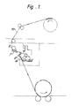
- fig.l shows a sketch in principle of a packaging machine,
- fig.2 shows a perspective sketch of the device, with the holding-on tool in cutting position,
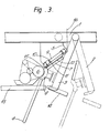
- fig.3 shows the cutting device in use in a packaging machine for paper rolls, the holding-on tool being indicated in both extreme positions. For a more detailed description, reference is made to an exemplified application of the invention via fig.3. The device is made so as to act jointly with a roller battery for various widths of roll, where the different webs are guideable backwards and forwards in relation to the cutting tool.
- The wrapping paper is guided through the gap 1, while the holding-on
tool 7 is in a fully retracted position 2. The paper is caught and guided by aguide 4 and brought forward and down towards the roll that is to be wrapped. This roll is rotating at a minimum speed of at least that of the feeding speed of the paper, and the paper is applied to the roll in one or more layers - always with the holding-on tool in the rear position. An adjustable length of web is to have glue applied to it, which occurs by the holding-on tool moving towards its second extreme position 3. The paper web is lifted by the holding-on tool up towards a guide contour 5, next coming into contact with a glue application roll 6 for application of glue to one side of the paper web by means of a holding-on tool 8 which is assembled with the holding-ontool 7 of the cutting tool. For cutting of the paper web a fast-working fluid power cylinder 9 is used, for instance an "Origa" cylinder, with a "rider" 10 connected to it which has acutting tool 11 mounted on it, for instance a knife, nail, etc. The cutting tool passes in aslot 12 in the holding-on tool, and the slot adopts an oblique angle in relation to the outer edge of the running web. - After cutting, the glue application continues right to the edge of the web end that is wound on to the roll. The other web end is retracted away from the cutting device and up towards the roll battery, so that the device may optionally receive paper of a different width.
- The cutting device according to the invention may also be applied without the use of a holding-on tool or base-table to webs that are under tensile stress.
Claims (9)
1. A method for cutting a running web (16) of for instance paper, plastic, textiles or similar materials,
characterized in that a cutting device (11) is guided from one outer edge of the web to the other along a course running at an oblique angle to the outer edge of the web, at such a speed in relation to the feeding speed of the web that a right angle or approximately right angle cut is obtained.
characterized in that a cutting device (11) is guided from one outer edge of the web to the other along a course running at an oblique angle to the outer edge of the web, at such a speed in relation to the feeding speed of the web that a right angle or approximately right angle cut is obtained.
2. A method according to claim 1,
characterized in that the running web is stretched.
characterized in that the running web is stretched.
3. A method according to claims 1 - 2,
characterized in that the cutting'is performed by means of a cutting or slitting tool (11), which is guided across one side of the web, running in a groove (12) in a holding-on tool (7) on the opposite side.
characterized in that the cutting'is performed by means of a cutting or slitting tool (11), which is guided across one side of the web, running in a groove (12) in a holding-on tool (7) on the opposite side.
4. A device for carrying out the method according to claims 1, 2, and 3, characterized in that it comprises a cutting tool (11), such as for instance a knife, nail etc., a device (9) giving the cuting tool high speed along a course which runs at an oblique angle in relation to the outer edge of the running web, and in that the course of the cutting tool runs parallel to the plane of the running web.
5. A device according to claim 4,
characterized in that it comprises a holding-on tool or base-table (7) with a slot (12), where the slot adopts an oblique angle in relation to the outer edge of the running web.
characterized in that it comprises a holding-on tool or base-table (7) with a slot (12), where the slot adopts an oblique angle in relation to the outer edge of the running web.
6. A device for interaction with a roll battery for different roll widths, where the different webs are guideable backwards and forwards in relation to the cutting tool,
characterized in that the holding-on tool is rotatable to and from the cutting tool so as to catch the web that is being advanced at the moment.
characterized in that the holding-on tool is rotatable to and from the cutting tool so as to catch the web that is being advanced at the moment.
7. A device according to claims 4 - 6,
characterized in that the holding-on tool (7) of the knife is assembled with a holding-on tool (8) devised to guide the web against a per se known glue application roll (6).
characterized in that the holding-on tool (7) of the knife is assembled with a holding-on tool (8) devised to guide the web against a per se known glue application roll (6).
8. A device according to claims 4 -7,
characterized in that a guide for the web at the exit from the glue application roll is rotatably attached to the holding-on tool, and in that it is rotatable by means of a fluid power cylinder (14) or a similar device, so as to catch the web end when the holding-on tool for the cutting device, the holding-on tool for the glue application roll, and the guide have been swung away from the cutting tool.
characterized in that a guide for the web at the exit from the glue application roll is rotatably attached to the holding-on tool, and in that it is rotatable by means of a fluid power cylinder (14) or a similar device, so as to catch the web end when the holding-on tool for the cutting device, the holding-on tool for the glue application roll, and the guide have been swung away from the cutting tool.
9. A device according to claims 4 -8,
characterized in that the cutting tool is mobile by means of a fast-working fluid power cylinder (9).
characterized in that the cutting tool is mobile by means of a fast-working fluid power cylinder (9).
Applications Claiming Priority (2)
| Application Number | Priority Date | Filing Date | Title |
|---|---|---|---|
| NO842464A NO154518C (en) | 1984-06-19 | 1984-06-19 | DEVICE FOR APPLICATION OF ADMINISTRATION ON A CONTINUOUS COURT AND CUTTING OF THE COURT AT THE ADMINISTRATION PLACE. |
| NO842464 | 1984-06-19 |
Publications (1)
| Publication Number | Publication Date |
|---|---|
| EP0169182A2 true EP0169182A2 (en) | 1986-01-22 |
Family
ID=19887719
Family Applications (1)
| Application Number | Title | Priority Date | Filing Date |
|---|---|---|---|
| EP85850210A Withdrawn EP0169182A2 (en) | 1984-06-19 | 1985-06-18 | Cutting device for a running web |
Country Status (3)
| Country | Link |
|---|---|
| EP (1) | EP0169182A2 (en) |
| FI (1) | FI852425L (en) |
| NO (1) | NO154518C (en) |
Cited By (1)
| Publication number | Priority date | Publication date | Assignee | Title |
|---|---|---|---|---|
| US6969300B2 (en) | 2002-02-28 | 2005-11-29 | Nina Himmer | Automated processing unit for a working station |
-
1984
- 1984-06-19 NO NO842464A patent/NO154518C/en unknown
-
1985
- 1985-06-18 EP EP85850210A patent/EP0169182A2/en not_active Withdrawn
- 1985-06-18 FI FI852425A patent/FI852425L/en not_active Application Discontinuation
Cited By (1)
| Publication number | Priority date | Publication date | Assignee | Title |
|---|---|---|---|---|
| US6969300B2 (en) | 2002-02-28 | 2005-11-29 | Nina Himmer | Automated processing unit for a working station |
Also Published As
| Publication number | Publication date |
|---|---|
| FI852425L (en) | 1985-12-20 |
| NO154518C (en) | 1986-10-08 |
| FI852425A0 (en) | 1985-06-18 |
| NO154518B (en) | 1986-06-30 |
| NO842464L (en) | 1985-12-20 |
Similar Documents
| Publication | Publication Date | Title |
|---|---|---|
| US4828195A (en) | Surface winder and method | |
| US4909452A (en) | Surface winder and method | |
| US4481053A (en) | Method and apparatus for splicing web | |
| US4962897A (en) | Web winding machine and method | |
| US4444360A (en) | Web severing apparatus in a web winding machine | |
| FI76390B (en) | FOERFARANDE OCH ANORDNING FOER SPETSDRAGNING AV EN BANA. | |
| CA2186811A1 (en) | Method and device for reeling a paper or board web | |
| JPS608941B2 (en) | Equipment for processing material in longitudinal motion | |
| CA1229547A (en) | Automatic roll change | |
| US4014233A (en) | Apparatus for severing a sheet of material from a web | |
| CZ22299A3 (en) | Grooving apparatus for rotary printing machines and process of feeding band-like material | |
| US6616088B2 (en) | Device for storing and unwinding rolls of material in bookbinding machines | |
| US4798351A (en) | Apparatus for coiling a foil web, especially a synthetic resin foil web | |
| EP0371892B1 (en) | Means for bagging folded compresses | |
| FI100324B (en) | Method and apparatus for cutting a web | |
| EP0169182A2 (en) | Cutting device for a running web | |
| DE19644079A1 (en) | Device for producing packaging from thin packaging material | |
| US4749139A (en) | Apparatus for severing a web | |
| FI83402C (en) | Paper path cutting device | |
| DE2655778C2 (en) | Device for making sections | |
| GB2300626A (en) | Web threading apparatus | |
| DE2165077A1 (en) | Automatic tape take-up device | |
| US5927047A (en) | Device and method in wrapping machine | |
| SE9103805D0 (en) | PROCEDURE AND DEVICE FOR PACKAGING | |
| US5240196A (en) | Cutting and feeding apparatus for webs of material on winding machines |
Legal Events
| Date | Code | Title | Description |
|---|---|---|---|
| PUAI | Public reference made under article 153(3) epc to a published international application that has entered the european phase |
Free format text: ORIGINAL CODE: 0009012 |
|
| AK | Designated contracting states |
Designated state(s): CH DE FR GB LI NL SE |
|
| STAA | Information on the status of an ep patent application or granted ep patent |
Free format text: STATUS: THE APPLICATION IS DEEMED TO BE WITHDRAWN |
|
| 18D | Application deemed to be withdrawn |
Effective date: 19880102 |
|
| RIN1 | Information on inventor provided before grant (corrected) |
Inventor name: KRISTIANSEN, FRANK |