EP0169075B1 - Multisource multireceiver method for geophysical exploration - Google Patents
Multisource multireceiver method for geophysical exploration Download PDFInfo
- Publication number
- EP0169075B1 EP0169075B1 EP85305160A EP85305160A EP0169075B1 EP 0169075 B1 EP0169075 B1 EP 0169075B1 EP 85305160 A EP85305160 A EP 85305160A EP 85305160 A EP85305160 A EP 85305160A EP 0169075 B1 EP0169075 B1 EP 0169075B1
- Authority
- EP
- European Patent Office
- Prior art keywords
- seismic
- action
- lines
- concord
- signals
- Prior art date
- Legal status (The legal status is an assumption and is not a legal conclusion. Google has not performed a legal analysis and makes no representation as to the accuracy of the status listed.)
- Expired - Lifetime
Links
Images


Classifications
-
- G—PHYSICS
- G01—MEASURING; TESTING
- G01V—GEOPHYSICS; GRAVITATIONAL MEASUREMENTS; DETECTING MASSES OR OBJECTS; TAGS
- G01V1/00—Seismology; Seismic or acoustic prospecting or detecting
- G01V1/28—Processing seismic data, e.g. analysis, for interpretation, for correction
- G01V1/284—Application of the shear wave component and/or several components of the seismic signal
-
- G—PHYSICS
- G01—MEASURING; TESTING
- G01V—GEOPHYSICS; GRAVITATIONAL MEASUREMENTS; DETECTING MASSES OR OBJECTS; TAGS
- G01V1/00—Seismology; Seismic or acoustic prospecting or detecting
- G01V1/003—Seismic data acquisition in general, e.g. survey design
-
- G—PHYSICS
- G01—MEASURING; TESTING
- G01V—GEOPHYSICS; GRAVITATIONAL MEASUREMENTS; DETECTING MASSES OR OBJECTS; TAGS
- G01V2210/00—Details of seismic processing or analysis
- G01V2210/60—Analysis
- G01V2210/62—Physical property of subsurface
- G01V2210/626—Physical property of subsurface with anisotropy
Definitions
- the present invention relates generally to the field of geophysical exploration. Specifically, a novel method and system of obtaining, interpreting, processing, and displaying seismic data having improved quality as well as new information concerning the earth's subterranean formations are disclosed. Additionally, an improved shear wave seismic exploration technique is disclosed in which a shear wave seismic survey line of profile can be laid without prior knowledge of or regard for the geological character of the earth's subterranean formations.
- shear wave seismic exploration techniques have employed shear wave seismic sources and shear wave seismic receivers in a seismic survey to gather seismic data.
- a seismic survey has been either linear or areal in its extent.
- the seismic energy imparted by the shear wave seismic source is detected by the shear wave seismic receivers after interacting with the earth's subterranean formations.
- Such seismic surveys have been limited to utilizing a shear wave seismic source having a single line of action or polarization, oriented with respect to the seismic survery line of profile, to preferentially generate seismic waves of known orientation, e.g., horizontal shear (Sh) waves or vertical shear (Sv) waves.
- the shear wave seismic receivers utilized in conjunction with a given shear wave seismic source have similarly been limited to a single line of action or polarization, oriented with respect to the seismic survey line of profile, to preferentially receive a single component of the seismic wave, e.g., (Sh) wave or (Sv) wave.
- the term "line of action” generally comprehends a defined vector displacement, such as the particle motion of the seismic wave.
- the lines of action of the seismic source and the seismic receivers have the same orientation relative to the line of profile and are said to be "matched”.
- compressional (P) waves are longitudinal waves where the particle motion is in the direction of propagation.
- Shear waves are transverse waves where the particle motion is in a transverse plane perpendicular to the direction of propagation.
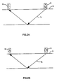
- Two special classes of shear waves are defined herein. Specifically, horizontal shear (Sh) waves where the particle motion in the transverse plane is further restricted to be perpendicular to the line of profile of the seismic survey E (i.e., horizontal) and vertical shear (Sv) waves where the particle motion in the transverse plane is further restricted to be perpendicular to the horizontal shear (Sh) particle motion all of which is shown in Figure 1.
- (Sh) waves and (Sv) waves have been utilized to detect and measure the anisotropic properties of an azimuthally anisotropic subterranean formation when the seismic lines of profile are properly oriented with respect to the surfaces of the symmetry planes and matched sets of shear wave seismic sources and shear wave seismic receivers have been deployed in the seismic survey.
- (Sh) and (Sv) shear wave seismic sources and seismic receivers are utilized, but only in matched sets, i.e., (Sh) shear wave seismic sources with (Sh) shear wave seismic receivers and (Sv) shear wave seismic sources with (Sv) shear wave seismic receivers.
- the (Sh) wave and (Sv) wave lines of action for the seismic source S and seismic receiver R are defined with respect to the line of profile of the seismic survey E.
- the orientation of the seismic survey line of profile with respect to the symmetry planes is critical. Consequently, utilisation of matched sets of shear wave seismic sources and shear wave seismic receivers have produced inconsistent results when the seismic survey line of profile has not been properly laid out with respect to the anisotropic geological character of the subterranean formations.
- the present invention consists in one aspect in a method for geophysical exploration of the earth's subterranean formations comprising the step of collecting a concord of seismic signals by imparting seismic wave energy into the earth subterranean formations along at least two linearly independent lines of action and receiving at least two linearly independent components of the seismic wave energy imparted along each line of action after it has interacted with the earth's subterranean formations.
- linearly independent is a mathematical expression used to indicate that information contained in a first line of action cannot be obtained through a linear combination of other lines of action; i.e., the information is not redundant.
- the present invention consists in a method for processing a concord of seismic signals acquired with sets of seismic sources having at least two lines of action and seismic receivers having at least two lines of action, comprising the steps of: obtaining a concord of seismic signals; and transforming the concord of seismic signals into a synthetic concord of seismic signals.
- a seismic survey is laid out without regard for or knowledge of the geological character of the earth's subterranean formations.
- Elements in a set of seismic sources adapted to impart seismic wave energy into the earth's subterranean formations along at least two linearly independent lines of action are positioned at selected source locations.
- Elements in a set of seismic receivers adapted to detect at least two linearly independent components of the imparted seismic wave energy are positioned at selected receiver locations.
- Each element in the set of the seismic receivers is adapted to generate an electrical signal or trace containing information regarding the geological character of the subterranean formation.
- An ensemble of such seismic signals is obtained for selected combinations of source locations and receiver locations.
- the system may further include an orientation module adapted to generate synthetic concords of seismic signals corresponding to synthetic orientations of the lines of action of the elements in the sets of the seismic sources and elements in the sets of seismic receivers so as to focus on a particular component of the imparted seismic wave energy.
- a concord of synthetic seismic sections produced from synthesized components of the detected seismic wave energy in the synthetic concord of seismic signals can aid in inferring the geological character of the subterranean formations.
- the synthetic concords of seismic signals correspond to a synthesized rotation of the lines of action of the elements in the sets of seismic sources and/or the sets of seismic receivers so as to focus on a particular component seismic wave energy.
- the orientation module is adapted to operate on either an unstacked concord of seismic signals or on a stacked concord of seismic signals.
- the synthetic concords of the seismic signals or traces can focus on any one of a plurality of components of the seismic wave energy with respect to the geological character of the subterranean formations and thus provides a method for inferring various features of the subterranean formations.
- a method and system of shear wave geophysical exploration are disclosed utilizing a shear wave seismic source imparting seismic shear wave energy at each source location in the seismic survey along at least two linearly independent lines of action and at least two shear wave seismic receivers at each receiver location in the seismic survey.
- Each shear wave seismic receiver has linearly independent lines of action adapted to detect a component of the imparted seismic wave energy.
- the orientation module has the effect of synthetically rotating the lines of action of the elements within either the set of seismic sources or the set of seismic receivers or both, into new lines of action.
- the resulting synthetic concords of seismic signals thus appears as if they had been originally acquired with sets of seismic sources and/or sets of seismic receivers having elements with such synthesized new lines of action.
- shear wave seismic data in a given seismic survey with shear wave seismic sources and shear wave seismic receivers having fixed lines of action and thereafter synthetically rotating the lines of action affords a significant improvement in the shear wave seismic data quality as well as the interpretation thereof.
- the present invention further includes a method of displaying the concords of seismic signals as a concord of seismic data as well as displaying the synthetic concords of seismic signals as synthetic concords of seismic data.
- the synthetic seismic data produced from the synthetic concords of seismic signals are generated by the operation of the orientation module so as to focus on different components of the seismic wave energy and to provide a method of interpreting the geological character of the subterranean formation.
- a set of seismic receivers R is located at a specified location in a seismic survey E.
- Each set of seismic receivers R includes elements adapted to detect a component of the imparted seismic wave energy.
- the elements in the set of seismic receivers R have linearly independent lines of action r 1 and r 2 .
- a set of seismic sources S is adapted to impart preferred components of seismic wave energy into the earth's formation at a specified location in the seismic survey E.
- Each set of seismic sources S includes elements adapted to impart seismic energy into the earth along linearly independent lines of action s 1 and s 2 .
- the elements in the sets of seismic sources S and seismic receivers R are identified by their lines of action and are hereafter generally denoted s j and r i , respectively. This notation identifies both the element and the line of action of the element.
- seismic wave energy having a preferred line of action s 1 or s 2 is imparted into the earth's formations at the specified location in the seismic survey E.
- two components of the seismic wave energy imparted by each source element s j are detected by the receiver elements r i in the set of seismic receivers R.
- the seismic wave energy detected can be organized in the following matrix form where (r i , s j ) represents ordered pairs of the elements r i and s j in the set of seismic receivers R and the set of seismic sources S: and where ⁇ ij connotes a general collection of seismic signals generated for receiver element r i of the set of seismic receivers R in response to the seismic energy imparted into the earth's subterranean formations by source element s j in the set of seismic sources S.
- a specific collection of seismic signals ⁇ ij for all indices i and j represents the seismic signals generated by the independent initiation of the source elements s j in the set of seismic sources S along at least two linearly independent lines of action s, and S2 each detected by elements r i of the set of seismic receivers along at least two linearly independent lines of action r, and r 2 and is hereafter designated a concord of seismic signals K.
- K can represent a concord of seismic signals ⁇ ij generated from seismic energy imparted by a set of seismic sources S having three three elements s 1 , S2 and s 3 and detected by a set of seismic receivers R having three r 1 , r 2 , and r 3 .
- Each element s j and r j have linearly independent lines of action.
- Equations (1) and (2) Those skilled in the art recognize the relationship between Equations (1) and (2); however, to simplify the nature of the forthcoming description only those sets of seismic sources S and sets of seismic receivers, limited to elements having only two linearly independent lines of action, will be discussed.
- pairs of the elements s j of the set of seismic sources S and the elements r 1 in the set of seismic receivers R can have the same lines of action.
- the general collection of seismic signals ⁇ ij will be understood, hereinafter, to also comprehend the specific collection of seismic signals designated a concord of seismic signals K. That is, the concord of seismic signals K defines the minimum usable collection of seismic signals ⁇ ij As will be shown later, various seismic data acquisition techniques can be employed to form a concord of seismic signals K.
- this notation is intended to indicate that the elements in the set of seismic sources S and the seismic receivers R have different lines of action or polarization and are said to be "unmatched".
- the consequence of employing unmatched pairs of source elements s j and receiver elements r ; is to produce unmatched components of the seismic signals, e.g., ⁇ 12 and ⁇ 21 .
- the general notation (r ; , s i ) comprehends both matched and unmatched pairs of elements of sets seismic sources S and seismic receivers R.
- the seismic wave energy imparted by elements s j in the set of seismic sources S and detected by the elements r ; in a set of seismic receivers R is represented by the seismic signals ⁇ ij .
- the seismic signals ⁇ ij contain information regarding the geological character of the subterranean formation. It is understood by those skilled in the art that the seismic signals ⁇ ij can be collected in a seismic survey E for a plurality of ordered pairs of seismic source locations Sq and receiver locations Rp as shown generally in Figure 3.
- this is geneally denoted ( ⁇ ij ) pq ; i.e., the seismic response observed by the element r ; in the set of seismic receivers R located at Rp resulting from the seismic energy imparted by the elements s j a set of seismic sources S located at Sq.
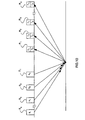
- multiple source locations S 1 , S 2 , ..., Sq and multiple receiver locations R 1 , R 2 , ..., Rp are laid out in the seismic survey E. It is further understood that the seismic survey E can either be linear or areal in extent.
- the source elements Sj in the set of seismic sources S are adapted to impart seismic wave energy into the earth's formations along at least two linearly independent, lines of action s 1 and s 2 .
- the receiver elements r i in the set of seismic receivers R are adapted to detect seismic wave energy in at least two linearly independent, lines of action r 1 and r 2 .
- the seismic signals ( ⁇ ij ) pq can be processed, for example common depth point (CDP) processing techniques, to form either CDP stacked seismic signals ⁇ ij or a common depth point gathers of seismic signals ⁇ ij .
- CDP common depth point
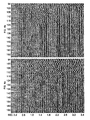
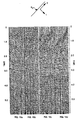
- the concord of CDP stacked seismic data shown in Figures 4a-d were created from the elements of the stacked seismic signals ⁇ ij , i.e., ⁇ 11 , ⁇ 21 ,. ⁇ 12 and ⁇ 22 .
- Each element of the CDP stacked seismic signals ⁇ ij is formed by stacking elements of the seismic signal ( ⁇ ij ) pq , e.g., ( ⁇ 11 ) pq . Since this collection of seismic signals ⁇ ij is for all i and j, the collection of seismic data displayed in Figures 4a-d is referred to as a concord of seismic data.
- Figures 4a and 4d represent CDP stacked seismic data produced with elements s j in the set of shear wave seismic sources S and elements r 1 in the set of shear wave seismic receivers R having matched lines of action.
- the seismic data of Figure 4a is developed from the CDP stacks of the seismic signals ⁇ 22 and the seismic data of Figure 4d is developed from the CDP stacks of the seismic signals ⁇ 11 . Even to the trained eye, the seismic data of Figures 4a and 4d lack sufficient correlation of seismic events and are thus not interpretable.
- the seismic data of Figures 4b and 4c are CDP stacked seismic data developed from the CDP stacks of the seismic signals ⁇ 12 and ⁇ 21 , respectively.
- the elements s j and r i in the sets of seismic sources S and seismic receivers R have unmatched lines of action which are orthogonal one to the other. It is clear even to the untrained eye that significant spatially coherent energy is present in both Figures 4b and c.
- both CDP stacks of the seismic signals ⁇ 12 and ⁇ 21 were believed to contain only noise, i.e., no spatially coherent seismic events. In this case, the misconceptions stem from ignoring the effects of azimuthal anisotropy in the subterranean formations.
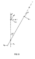
- Figure 5 shows the orientation of a line in profile of seismic survey E with respect to the lines of action of the elements s 1 and S2 and of the elements r 1 and r 2 of the set of seismic receivers R as well as the inferred orientation of the planes of symmetry A in subterranean formation.
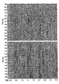
- the anomalous appearance of the CDP stacked seismic data in Figures 4a-d can also be observed in a concord of common source point gathers of seismic data displayed in Figures 6a-d produced from common source point gathers of the seismic signal ( ⁇ ij ) pq designated as ⁇ ij taken along the same line of profile E 1 .
- the concord of seismic data displayed in Figures 6a-d are developed from a single source location Sq and at sixty (60) different receiver locations Rp.
- the elements of the seismic data shown in Figures 6a-d are for different pairings of the elements r i and s j in the set of seismic receivers R and the seismic sources S.
- correlation of events is difficult on such "raw data”, it is certainly anomalous to record the significant seismic energy on the unmatched seismic signals, ⁇ ' 12 and ⁇ ' 21 , in seismic sections 6b and 6c.
- the seismic energy is received with the elements r ; of the set of seismic receivers R having lines of action orthogonal to the lines of action of the elements Sj of seismic source S.
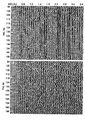
- a common source point gather of the seismic signals B ij are represented in the concord of seismic data of Figures 7a-d taken along the same line of profile in the seismic survey E.
- the elements r ⁇ i and ⁇ j in the set of seismic sources S and seismic receivers R have a different set of substantially orthogonal lines of action.
- the orientations of the elements r ⁇ 1 and ⁇ j were selected to be physically appropriate for the inferred anisotropy symmetry planes A of the subterranean formation as shown in Figure 5.
- An orientation module F will now be described which can synthetically rotate the lines of action of the elements r ; and s j to new synthetic lines of action of the elements r i and s j so as to correspond with the physically oriented lines of action of the elements r ⁇ i and ⁇ j previously describd or to any other desired orientation.
- the orientation module F operates on the seismic signals ⁇ ij to produce a synthetic seismic signals ⁇ cm having synthetic lines of action generally different from those of the original seismic signals ⁇ ij . It is instructive to recall at this juncture that the indices i,j and c,m are dummy variables and that the changes from indices i,j to c,m have been employed merely as an aid in further differentiating between the seismic signals ⁇ ij and ⁇ ij and the synthetic seismic signals ⁇ cm . As will be discussed later, optimizing the selection of a particular rotation of the synthetic of seismic signals ⁇ cm can be used to infer the geological character of the subterranean formation by focusing on a particular component of the seismic wave energy.
- the receiver operator C ci is adapted to transform the lines of action of the elements r i in the set of seismic receivers R into a synthetic set of lines of action for the elements r c for a synthetic set of seismic receivers R.
- the receiver operator C ci is thus a vector rotation adapted to transform the original set of linearly independent lines of action for the elements r i in the set of seismic receivers R into a synthetic set of linearly independent lines of action for the elements r c in the set of synthetic seismic receivers R.
- the source operator M jm is adapted to transform the lines of action of the elements Sj of the set of seismic source S into a set of synthetic lines of action of the elements s m for a synthetic set of seismic sources S.
- the source operator M jm is thus a vector rotation adapted to transform the first set of linearly independent lines of action for the elements Sj in the set of seismic sources S into a synthetic set of linearly independent lines of action for the elements s m of a synthetic seismic source S.
- the orientation module F in the preferred embodiment is a computer processing unit adapted to implement the source operator M jm and the receiver operator C ci ;.
- a flow process for the operation of the orientation module F is shown in Figures 11 and 12 and will be discussed later.
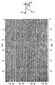
- orientation module F The benefits of the orientation module F are vividly demonstrated by comparing the CDP stack of the seismic signals ⁇ ij portrayed in Figures 4a-d with the synthetic CDP stack of the seismic signals ⁇ cm , portrayed in Figures 8a ⁇ d.
- the concord of seismic data of Figure 4 are CDP stacked seismic data produced from the CDP stack of the signals ⁇ ij , i.e., the seismic signal of element r ; of the set of seismic receivers R from seismic energy imparted by the element s j in the set of seismic sources S.
- the CDP stacked seismic signals ⁇ 22 and ⁇ 11 represented in seismic sections Figures 4a and 4b correspond to the results of seismic exploration where the elements r ; and Sj of the set of seismic sources S and seismic receivers R have matched lines of action.
- CDP stacked seismic signals B 12 and B 21 heretofore believed to be substantially noise, represented in the seismic sections Figures 4b and 4c correspond to the seismic signals obtained with the elements r ; and Sj of the set of seismic sources S and the seismic receivers R having unmatched lines of action.
- Figures 8a-d are a synthetic concord of CDP stacked seismic data produced by the operation of the orientation module F on the concord of CDP stacked seismic signals B ij and displayed in Figures 4a-d.
- the orientation module F in this case, has been employed to reduce the effects of shear polarization splitting or birefringence by synthesizing new lines of action for the elements r ; and s j in the set of seismic sources S and seismic receivers R such that the new synthetic lines of action of the elements r c , s m are appropriately aligned with respect to symmetry planes A shown in dashed lines of Figure 5.
- the useful seismic energy in the seismic signals shown in Figures 8a and b has been increased whereas the useful seismic energy has been decreased in the seismic signals shown in Figures 8b and c.
- the physical orientation of the lines of action of the elements ⁇ j and r ⁇ i in the set of seismic sources S and the seismic receiver R is feasible after the appropriate orientation is known, the use of the orientation module F offers more practicability.
- the orientation module F can be employed to rotate the lines of action of the elements s j and r i in the set of seismic sources S and seismic receiver R, if desired, to any orientation provided a complete collection of seismic signals ⁇ ij is available, i.e., a concord of seismic signals K.
- the synthesized seismic signals ⁇ cm represented in synthesized concord of common source point gathers of seismic data of Figures 9a-d simulates the result that would have been obtained had the lines of action of the elements r c and s m in the set of seismic sources S and seismic receivers R been oriented as were the elements r ⁇ i and ⁇ j in the set of seismic receivers R and seismic sources S used to produce Figures 7a-d.
- the seismic data of Figures 9b and c indicate that the seismic energy developed by the unmatched seismic signals ⁇ 21 , and ⁇ 12 has been substantially transferred to the seismic signals ⁇ 22 and ⁇ 11 depicted in the seismic sections of Figures 9a and 9d thereby simplifyng the problems of interpreting the concord seismic sections.
- seismic sections of Figures 9a and 9d now exhibit the desired correlation amongst seismic events, and hence, can be used to interpret the geologic character of the subterranean formation.
- the operation of the orientation module F can be thought of as vectorially rotating the lines of action of the elements r i and s j in the set of seismic sources S and seismic receivers R to accentuate a particular component of the seismic wave energy in order to infer the geological character of subterranean formations.
- the synthetic concords of seismic data of Figures 8a-d and 9a-d can enhance the interpretation of the geological character of the subterranean formations with seismic data obtained with shear wave synthetic sources and shear wave seismic receivers when heretofore such interpretation has not been generally obtainable.
- the subterranean formation represented in the concords of seismic data in Figures 4, 6, 7, 8 and 9 is an azimuthally anisotropic media having generally parallel planes of symmetry as generally indicated by the dashed lines of Figure 5.
- the synthetic lines of action of the elements s m , in the set of seismic sources S and the elements r c in the set of seismic receivers R produced by orientation module F are also shown in Figures 5 and are seen to be substantially either parallel or perpendicular to the inferred planes of symmetry of the azimuthally anisotropic media.
- the orientation module F cannot produce meaningful results unless a concord of seismic signals K is originally obtained.
- existing techniques for collecting geophysical data have heretofore been limited to utilizing a first set of synthetic sources S and seismic receivers R having elements s, and r 1 with matched lines of action to produce seismic signals ( ⁇ 11 ) pq .
- More recent techniques have added a second set of seismic sources S and seismic receivers R having elements s 2 and r 2 with matched lines of action but different from s 1 and r, to produce seismic signals ( ⁇ 22 ) pq .
- seismic wave energy is imparted by each element s j in the set of seismic sources S at source location Sq and each element r i in the set of seismic receivers R is adapted to detect the seismic energy at receiver locations Rp.
- this scheme is preferred, there are innumerable alternate schemes for acquiring a concord of seismic signals K as would be obvious to one skilled in the art.
- Figure 10 utilizes the same elements r i in a set of seismic receivers R at the seismic receiver locations Rp as shown in Figure 2 and 3. However, rather than imparting seismic wave energy at each source location Sq with both elements s, and s 2 in the set of seismic sources S, the seismic wave energy is imparted at every other source location Sq by alternating elements s 1 and s 2 .
- the seismic signals ⁇ ij are processed for a common depth point, a usable albeit non-ideal, concord of CDP stacked seismic signals K can be obtained (this results from the summation of station locations involved in CDP process).
- the CDP summation of the seismic signals ( ⁇ ij ) pq is now amenable to operation by the operation module F.
- a similar decimation on the elements r i of the set of seismic receivers R can also produce a usable, albeit non-ideal, concord of seismic signals K when processed for a common depth point.
- the orientation module F can generate synthetic seismic signals ⁇ cm having the elements r c and s m with new lines of action by a linear combination of the seismic signals ⁇ ij .
- the synthetic lines of action for the receiver elements r c are a linear combination of the original linearly independent lines of action r, and r 2 .
- the synthetic lines of action for the source elements s m are a linear combination of the original linearly independent lines of action s 1 and s z . That is to say, given a complete set of seismic receivers R, the lines of action of the receiver elements r i can be transformed to a new line of action r c via the receiver operator C ci ; without having a complete set of source elements s j and given a complete set of seismic sources S, the lines of action source elements s i can be transformed into new lines of action s m via the source operator Mm without having a complete set of seismic receivers R.
- a plurality of concords of seismic signals K can be acquired for selected combinations of the source locations Sq and the receiver locations Rp in a seismic survey E.
- a shear wave seismic source S e.g., a shear wave vibrator having a fixed line of action
- seismic energy such as SH wave
- the seismic source S fixed line of action is rotated into a second orientation s 2 with respect to the seismic line of profile E and seismic energy, such as SV, is imparted into the earth's formation along the second line of action s 2 .
- the lines of action s, and S2 are substantially mutually perpendicular although other orientations can be employed.
- at least two seismometers R are placed at each receiver location Rp and each are adapted to receive different components r, and r 2 of the seismic energy imparted.
- the seismic receivers have (Sh) wave and (Sv) wave lines of action.
- the lines of action r, and r 2 in the set of seismic receivers R are substantially mutually perpendicular although other orientations can be employed.
- seismic energy having a compressional (P) wave line of action s 3 can be imparted at each source location Sq and the set of seismic receivers R can also include an element r 3 for receiving seismic wave energy having a (P) wave line of action at each receiver location Rp.
- each element r in the set of seismic receivers detects a component of the seismic wave energy imparted by each elements; in the set of seismic sources.
- the seismic survery is laid out on the earth's surface without regard or knowledge of the geologic characteristics of the subterranean formation.
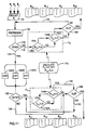
- Block 100 represents a collection of all seismic signals ( ⁇ ij ) pq obtained in a seismic survey for selected combinations of source locations Sq and receiver locations Rp. Proceeding to Block 105, the of seismic signals ( ⁇ ij ) pq are processed including correlation, filtering, normal moveout correction, etc.
- Block 110 is then entered and a decision is made whether to stack the seismic signals ( ⁇ ij ) pq before or after the operation of orientation module F. Proceeding first in a direction of a decision of stack before implementing the orientation module F, either block 120A or 120B or 120C is entered. Blocks 120A, 120B, and 120C each represent the different methods of stacking of the seismic signals ( ⁇ ij ) pq by way of examples common depth point, common source point and common receiver point, respectively.
- the orientation module F 1 includes a source operator M jm (t,x) designated in Block 140A and a seismic receiver operator C ci (t,x) designated in Block 140B.
- the seismic source operator M jm (t,x) is a specified vector rotation adapted to transform the linearly independent lines of action of the elements s j in the set of seismic source S and to synthetic lines of action s m different from that of the elements s j .
- the seismic source operator M jm (t,x) is time-dependent and spatially dependent; i.e., the source operator M jm (t,x) can produce different vector rotations as a function of time and spatial location. Since the seismic signals ( ⁇ ij ) pq are implicitly dependent upon time and spatial location, operation of a time-dependent and spatially-dependent source operator M jm (t,x) can more accurately describe variations in the geological characteristics of subterranean formations which can vary as a function of both depth and spatial location.
- the receiver operator C ci (t,x) is a time-dependent and spatially-dependent vector rotation; i.e., the receiver operator C ci (t,x) can produce different vector rotations as a function of both time and spatial location.
- the receiver operator C ci (t,x) is a specified vector rotation adapted to transform the linearly independent lines of action of the elements r i of the set of seismic receivers R into synthetic lines of action of the receiver elements r c different from that of the elements r ; .
- Block 140A thus represents a decision whether or not to impress source operator M jm (t,x) on the stack of seismic signals ( ⁇ ij ) pq .
- the extent of rotation of the source operator M jm (t,x) is determined in Block 170 and communicated to the orientation module F,. The steps of calculating the receiver operator M jm (t,x) will be discussed later.
- Block 140B is entered and a decision is made whether or not to impress the receiver operator C ci (t,x) on the stack of seismic signals ( ⁇ ij ) pq .
- the extent of rotation by the receiver operator C ci (t,x) is determined in Block 170 and communicated to the orientation module F. The step of calculating the receiver operator C ci (t,x) will be discussed later.
- the orientation module F 1 can produce one of three results: first, the operation of the source operator alone M jm (t,x); second, the operation of the receiver operator C ci (t,x) alone; and third, the combined operation of both source and receiver operators C ci (t,x) and M jm (t,x).
- the synthesized stack of seismic signals ( ⁇ cm ) pq which have been produced by the orientation module F 1 are then directed to Block 150 whereby seismic sections traces can be produced for each of the components in the stack of seismic signals ( ⁇ ij ) pq ; i.e., ⁇ 11 , ⁇ 12 , ⁇ 21 , and ⁇ 22 .
- the orientation module performs an identity rotation of the seismic signals ( ⁇ ij ) pq
- the concord of seismic sections ⁇ ij as shown in Figure 4, can be thought of as displaying the components of the seismic signals ⁇ ij as actually obtained.
- the orientation module performs a selected rotation of the stack of seismic signals ( ⁇ ij ) pq , a synthetic concord of seismic data is produced which can be thought of as displaying the synthetic seismic signals ⁇ cm . Iterations in the extent of rotation by the orientation module F, can produce a plurality of synthetic seismic sections having incremental rotations.
- a seismologist reviews a plurality of the synthetic concords of seismic data to ascertain which incremental rotation brings into focus the geological characteristics of interest in the subterranean formations.
- the technique of focusing the seismic energy of the seismic wave so as to enhance the geological characteristics of the subterranean formation can be conceptualized as maximizing the output of the seismic energy inpartd into the ground onto various of the synthetic concord of seismic sections.
- FIG. 170 calculation means are provided for determining the extent of rotation orientation module F by determinng individually the extent of rotation of both the source operator M jm (t,x) and the receiver operator C ci (t,x). Specifically looking at Figure 12, and iterative process whereby the operators are calculated is shown.
- Figure 12 is an expanded flow diagram, detailing the iterative steps of the calculation Block 170 in Figure 11.
- Figure 12 discloses an iterative process for calculating the extent of rotation of the operators C ci (t,x) and M jm (t,x) for specified time window At and a specified spatial location selected in Block 200. That is, the operators C ci (t,x) and M jm (t,x) will operate only over a selected time window At of the seismic signal C ij for a given spatial location x,.
- the time window At is equal to the record length of the seismic signal ⁇ ij and further iterations of time are not considered.
- a first time window ⁇ t 1 is selected in Block 200, a first extent of rotation of the operators C ci ( ⁇ t 1 ,x 1 ) and M jm ( ⁇ t 1 ,x 1 ) can be calculated as shown in Block 210 and thereafter such extent of rotation is communicated to the orientation module F such that a first concord of synthetic seismic data produced from the seismic signals ⁇ ij can be obtained.
- a second time window At 2 is selected in Block 220.
- the step of rotation of the operator C ci ( ⁇ t 2 ,x 1 ) and M jm ( ⁇ t 2 ,x 1 ) is calculated for the time window At 2 and communicated to the orientation module F such that additional concords of synthetic seismic data can be obtained. Further iterations the extent of rotation of operator C ci ( ⁇ t 2 ,x 1 ) and C jm ( ⁇ t 2 ,x 1 ) are communicated by feedback loop 235 similar to the previous discussion.
- the process of selecting a time window ⁇ t n and thereafter iteratively calculating the extent of rotation operator C ci ( ⁇ t n ,x 1 ) and M jm ( ⁇ t n ,x 1 ) and plotting the concords of synthetic data can be contained for as many sub-divisions of time as required. Additionally by way of feedback loop 255, the spatial location can be indexed to the next spatial location X 2 and the entire process repeated, thus making both operators dependent on both time and spatial location.
- a decision not to stack the concords of seismic signals ( ⁇ ij ) pq before impressing the operator C ci (t,x) and M jm (t,x) proceeds directly to the orientation module F 2 . Thereafter the previously discussed operation of the orientation module in cooperation with the iterative process for ascertaining the extent of rotation of the operator G jl ( ⁇ t,x) and M jm (At,x) is carried out.
- the seismic signals ⁇ ij which have been processed by the orientation module are displayed as synthetic concords of seismic data.
- the resulting synthetic concord of seismic data can either be produced from selected gathers of the seismic signals ⁇ ij or alternatively any other mode of gathering the seismic signals ( ⁇ ij ) pq such as common depth point, common depth source point, common receiver point, etc.
- FIG. 13 a topographical overview of two different line of profile E, and E 2 are shown schematically.
- the line of profile E insects the line of profile E 2 with an included angle of approximately 60°C.
- These lines of profile were laid out in Dilley, Texas, which was known to contain an azimuthally anisotropic subterranean formation.
- the symmetry planes of such formations were generally aligned perpendicularly to the line of profile E 2 .
- Seismic source locations Sq and seismic receiver locations Rp were laid out along both lines of profile. Superimposed on each line of profile are the lines of action of the source and receiver elements with arrows labeled either 1 or 2.
- the elements r ; in the set of seismic receivers R were (Sh) wave and (Sv) wave type receivers while the seismic source was a shear wave vibrator having a fixed line of action which was rotated approximately 90° with respect to the seismic line of profile between acquistion cycles to impart either (Sv) or (Sh) wave energy along the lines of profile.
- Figures 14a-d the quality of the concord of CSP seismic data shown thereon, especially Figures 14a and d corresponding to seismic signals ⁇ 22 and ⁇ 11 taken along line of profile E 1 , is uniformly poor and not interpretable since neither seismic line of profile E 1 nor the lines of action s 1 , S2 and r 1 and r 2 were properly oriented with the inferred symmetry planes of the azimuthally anisotropic subterranean formation.
- the seismic data of Figure 15a aand 15d corresponding to the seismic signals ⁇ 22 and ⁇ 11 taken along the line of profile E 2 show good correlation of the seismic events.
- line of profile E 2 was oriented such that the lines of action s 1 , S2 and r 1 , r 2 were properly oriented with respect to the inferred symmetry planes of the azimuthally anisotropic subterranean formation.
- FIGS 16a-d a synthetic concord of common source point gathers of seismic data derived from the common source point gathers of the seismic signals ( ⁇ ij ) pq along the line of profile E 1 now show good correlation and interpretability.
- the synthesized concord of seismic data shown in Figures 16a-d are the result of a synchronous rotation of the lines of action of the elements s 1 and s 2 the set of seismic sources S and of the lines of action of the elements r 1 and r 2 in the set of seismic receivers R through approximately 30° of rotation.
- each seismic line of profile was linear; however, lines of profile are more generally curvilinear as shown in Figure 17.
- the seismic line of profile E 3 in Figure 17 can be curvilinear for a number of reasons including surveying errors, avoiding physical objects such as trees, houses, roads, lakes, etc. Nevertheless, the orientation of the elements r i and s j of the set of seismic receivers R and seismic sources S are fixed with respect to the seismic line of profile E 3 at each source and receiver location Sq and Rp as shown by the arrows numbered 1 and 2.
- the lines of action of the elements r i and s j can be uniformly aligned either relative to the geological character of the subterranean formation orto the horizontal surface of the earth as seen by the arrows numbered and 2.
- the present method of acquiring geophysical information and the further processing and displaying techniques disclosed herein transforms and otherwise uninterpretable seismic data into a useful form.
- the effect of the operation of the orientation module F is a two-dimensional planar rotation of the lines of action of the elements r, and r 2 and s 1 and s 2 .
- orientation module F is a three-dimensional volumetric rotation of the lines of action r,, r 2 , r 3 , and s 1 , s 2 , s 3 .
- the concord of seismic signals K also comprehends utilizing three seismic receivers and seismic sources each having independent, noncollinear lines of action.
- such a concord of seismic signals K could be obtained using mutally orthogonal sets of seismic sources and receivers such as are presently available; e.g., Sh, Sv and P wave sources and receivers.
- the present invention is not limited to the particular line of action of seismic sources and/or seismic receivers presently available.
Abstract
Description
- The present invention relates generally to the field of geophysical exploration. Specifically, a novel method and system of obtaining, interpreting, processing, and displaying seismic data having improved quality as well as new information concerning the earth's subterranean formations are disclosed. Additionally, an improved shear wave seismic exploration technique is disclosed in which a shear wave seismic survey line of profile can be laid without prior knowledge of or regard for the geological character of the earth's subterranean formations.
- Historically, shear wave seismic exploration techniques have employed shear wave seismic sources and shear wave seismic receivers in a seismic survey to gather seismic data. Such a seismic survey has been either linear or areal in its extent. The seismic energy imparted by the shear wave seismic source is detected by the shear wave seismic receivers after interacting with the earth's subterranean formations. Such seismic surveys, however, have been limited to utilizing a shear wave seismic source having a single line of action or polarization, oriented with respect to the seismic survery line of profile, to preferentially generate seismic waves of known orientation, e.g., horizontal shear (Sh) waves or vertical shear (Sv) waves. The shear wave seismic receivers utilized in conjunction with a given shear wave seismic source have similarly been limited to a single line of action or polarization, oriented with respect to the seismic survey line of profile, to preferentially receive a single component of the seismic wave, e.g., (Sh) wave or (Sv) wave. As used herein, the term "line of action" generally comprehends a defined vector displacement, such as the particle motion of the seismic wave. In present shear wave seismic surveys, the lines of action of the seismic source and the seismic receivers have the same orientation relative to the line of profile and are said to be "matched".
- As long as seismic surveys were limited to seismic sources and seismic receivers having a compressional (P) wave lines of action, satisfactory results were generally obtained irrespective of the orientation of the seismic survey lines of profile with respect to the underlying geological character of the subterranean formations. However, when the seismic sources and seismic receivers are of the shear wave type, i.e., either horizontal shear (Sh) wave or vertical shear (Sv) wave, the orientation of the seismic survey line of profile and/or the line of action of the shear wave seismic source with respect to the geological character of the subterranean formations can determine whether or not meaningful seismic data is obtained.
- As understood by those skilled in the art, compressional (P) waves are longitudinal waves where the particle motion is in the direction of propagation. Shear waves are transverse waves where the particle motion is in a transverse plane perpendicular to the direction of propagation. Two special classes of shear waves are defined herein. Specifically, horizontal shear (Sh) waves where the particle motion in the transverse plane is further restricted to be perpendicular to the line of profile of the seismic survey E (i.e., horizontal) and vertical shear (Sv) waves where the particle motion in the transverse plane is further restricted to be perpendicular to the horizontal shear (Sh) particle motion all of which is shown in Figure 1.
- Exemplary of the dependence of the orientation of the seismic survey line of profile with respect to the geological character of the subterranean formation, when matched shear wave seismic sources and shear wave seismic receivers are used, it is known by those skilled in the art that shear wave seismic surveys are adversely affected by azimuthally anisotropic subterranean formations. Azimuthally anisotropic subterranean formations have generally vertical parallel planes of symmetry. Because (Sh) waves and (Sv) waves interact differently with the symmetry planes of the azimuthally anisotropic subterranean formation, especially when the symmetry planes are either parallel to or perpendicular to the line of action of the shear wave, care must be taken to ensure that the seismic survey line of profile is laid out either parallel or perpendicular to the symmetry planes.
- When the seismic survey line of profile is laid out either parallel or perpendicular to the symmetry planes, the utilization of matched sets of (Sh) wave and (Sv) wave seismic receivers and seismic sources have been used to demonstrate the anisotropic geological character of a subterranean formation. Such a technique requires prior knowledge of the seismic velocity anisotropy of the subterranean formation to be successful.
- The interaction differences of (Sh) waves and (Sv) waves have been utilized to detect and measure the anisotropic properties of an azimuthally anisotropic subterranean formation when the seismic lines of profile are properly oriented with respect to the surfaces of the symmetry planes and matched sets of shear wave seismic sources and shear wave seismic receivers have been deployed in the seismic survey. In such applications, (Sh) and (Sv) shear wave seismic sources and seismic receivers are utilized, but only in matched sets, i.e., (Sh) shear wave seismic sources with (Sh) shear wave seismic receivers and (Sv) shear wave seismic sources with (Sv) shear wave seismic receivers.
- However, if the seismic survey line of profile is not properly oriented with respect to the planes of symmetry, the seismic information observed can be difficult to interpret at best.
- As shown in Figure 1, the (Sh) wave and (Sv) wave lines of action for the seismic source S and seismic receiver R are defined with respect to the line of profile of the seismic survey E. As such, the orientation of the seismic survey line of profile with respect to the symmetry planes is critical. Consequently, utilisation of matched sets of shear wave seismic sources and shear wave seismic receivers have produced inconsistent results when the seismic survey line of profile has not been properly laid out with respect to the anisotropic geological character of the subterranean formations.
- Those acquainted with the art of seismic exploration, especially in seismically virgin territory, realise that knowledge of the geological character of the subterranean formations is generally not available prior to seismic exploration. The method and system of geophysical exploration of the present invention can be advantageously employed without regard to or knowledge of the geological character of the subterranean formations and still obtain meaningful seismic data.
- The present invention consists in one aspect in a method for geophysical exploration of the earth's subterranean formations comprising the step of collecting a concord of seismic signals by imparting seismic wave energy into the earth subterranean formations along at least two linearly independent lines of action and receiving at least two linearly independent components of the seismic wave energy imparted along each line of action after it has interacted with the earth's subterranean formations.
- The term "linearly independent" as used herein is a mathematical expression used to indicate that information contained in a first line of action cannot be obtained through a linear combination of other lines of action; i.e., the information is not redundant.
- In another aspect, the present invention consists in a method for processing a concord of seismic signals acquired with sets of seismic sources having at least two lines of action and seismic receivers having at least two lines of action, comprising the steps of: obtaining a concord of seismic signals; and transforming the concord of seismic signals into a synthetic concord of seismic signals.
- In one aspect of the present invention, a seismic survey is laid out without regard for or knowledge of the geological character of the earth's subterranean formations. Elements in a set of seismic sources adapted to impart seismic wave energy into the earth's subterranean formations along at least two linearly independent lines of action are positioned at selected source locations. Elements in a set of seismic receivers adapted to detect at least two linearly independent components of the imparted seismic wave energy are positioned at selected receiver locations.
- Each element in the set of the seismic receivers is adapted to generate an electrical signal or trace containing information regarding the geological character of the subterranean formation. An ensemble of such seismic signals is obtained for selected combinations of source locations and receiver locations.
- The system may further include an orientation module adapted to generate synthetic concords of seismic signals corresponding to synthetic orientations of the lines of action of the elements in the sets of the seismic sources and elements in the sets of seismic receivers so as to focus on a particular component of the imparted seismic wave energy. A concord of synthetic seismic sections produced from synthesized components of the detected seismic wave energy in the synthetic concord of seismic signals can aid in inferring the geological character of the subterranean formations. The synthetic concords of seismic signals correspond to a synthesized rotation of the lines of action of the elements in the sets of seismic sources and/or the sets of seismic receivers so as to focus on a particular component seismic wave energy. The orientation module is adapted to operate on either an unstacked concord of seismic signals or on a stacked concord of seismic signals.
- The synthetic concords of the seismic signals or traces can focus on any one of a plurality of components of the seismic wave energy with respect to the geological character of the subterranean formations and thus provides a method for inferring various features of the subterranean formations.
- In one embodiment, a method and system of shear wave geophysical exploration are disclosed utilizing a shear wave seismic source imparting seismic shear wave energy at each source location in the seismic survey along at least two linearly independent lines of action and at least two shear wave seismic receivers at each receiver location in the seismic survey. Each shear wave seismic receiver has linearly independent lines of action adapted to detect a component of the imparted seismic wave energy.
- The orientation module has the effect of synthetically rotating the lines of action of the elements within either the set of seismic sources or the set of seismic receivers or both, into new lines of action. The resulting synthetic concords of seismic signals thus appears as if they had been originally acquired with sets of seismic sources and/or sets of seismic receivers having elements with such synthesized new lines of action.
- The ability to obtain shear wave seismic data in a given seismic survey with shear wave seismic sources and shear wave seismic receivers having fixed lines of action and thereafter synthetically rotating the lines of action affords a significant improvement in the shear wave seismic data quality as well as the interpretation thereof.
- The present invention further includes a method of displaying the concords of seismic signals as a concord of seismic data as well as displaying the synthetic concords of seismic signals as synthetic concords of seismic data. The synthetic seismic data produced from the synthetic concords of seismic signals are generated by the operation of the orientation module so as to focus on different components of the seismic wave energy and to provide a method of interpreting the geological character of the subterranean formation.
- The invention will now be described by way of example with reference to the accompanying drawings in which:
- Figure 1 is a schematic representation defining the relationship between a line of action and a line of profile in a seismic survey;
- Figures 2a-b are schematic examples of the present invention demonstrating the relationship of the lines of action for the elements ri and sj for a single set of seismic receivers and seismic sources;
- Figure 3 is a schematic example of the present invention employing multiple sets of seismic sources and seismic receivers;
- Figures 4a-d are a concord of common depth point (CDP) stacked seismic data obtained from field data;
- Figure 5 is a topographical view representing the relationship between the line of survey E, the lines of action of the elements r1, r2; r̂1, r̂2; s1, s2; ŝ1, ŝ2; and the inferred planes of symmetry A of the subterranean formation from which the field data was obtained;
- Figues 6a-d are a concord of common source point (CSP) seismic data corresponding to common source point gathers of seismic signals obtained with elements having lines of action r1, r2 and s1, S2;
- Figures 7a-d are a concord of common source point seismic data in which the original lines of action of the elements r1, r2; s1 and s2 used to obtain the seismic data shown in Figures 6a-d have been physically rotated into lines of action represented by the elements r̂1, r̂2 and ŝ1, and ŝ2 as shown in Figure 5;
- Figures 8a-d are a synthetic concord of CDP stacked seismic data in which the synthetic orientation of the lines of action of the elements r,, r2 and s1, s2 of the synthetic set of seismic sources and seismic receivers correspond to the physical lines of action of the elements r̂1, r̂2, and ŝ1, ŝ2 of the synthetic set of seismic sources and seismic receivers as shown in Figure 5.
- Figures 9a-d are a synthetic concord of common source point seismic data in which the synthetic lines of actions of the elements
r 1,r 2;s 1,s 2 correspond to the physical lines of action represented by the elements r̂1, r̂2; ŝ1, ŝ2 in Figure 5; - Figure 10 is a schematic representation of an alternative placement scheme of the elements ri and si in the sets of seismic receivers R and seismic sources S to obtain a concord of seismic signals;
- Figure 11 is a generalized process flow diagram of the method of the present invention;
- Figure 12 is a generalized process flow diagram of the operation of other orientation module;
- Figure 13 is a topographical view of the seismic survey lines of profile E1 and E2 and the orientation of the physical lines of action of elements si and ri in the sets of seismic sources and seismic receivers for the field data and synthetic lines of action of elements
s m andr c; - Figure 14 is a concord of common source point seismic data along line of profile E1;
- Figure 15 is a concord of common source point seismic data along line of profile E2;
- Figure 16 is a synthetic concord of common source point seismic data along the line of profile E1; and
- Figure 17 is a topographical view of a curvilinear seismic line of profile E3.
- In order to facilitate a more comprehensive understanding of the present invention, Table I and a brief discussion of the mathematical notation to be utilized are provided.

- Looking now to Figure 2a and b, a set of seismic receivers R is located at a specified location in a seismic survey E. Each set of seismic receivers R includes elements adapted to detect a component of the imparted seismic wave energy. The elements in the set of seismic receivers R have linearly independent lines of action r1 and r2. Additionally, a set of seismic sources S is adapted to impart preferred components of seismic wave energy into the earth's formation at a specified location in the seismic survey E. Each set of seismic sources S includes elements adapted to impart seismic energy into the earth along linearly independent lines of action s1 and s2. The elements in the sets of seismic sources S and seismic receivers R are identified by their lines of action and are hereafter generally denoted sj and ri, respectively. This notation identifies both the element and the line of action of the element.
- Upon the independent initiation of each source element sj in the set of seismic sources S, seismic wave energy having a preferred line of action s1 or s2 is imparted into the earth's formations at the specified location in the seismic survey E. After interacting with the subterranean formation, two components of the seismic wave energy imparted by each source element sj are detected by the receiver elements ri in the set of seismic receivers R.
- Figures 2a and 2b show by way of example, a set of seismic receivers R having elements with lines of action r1 and r2 and a set of seismic sources S imparting seismic wave energy along lines of action s1 and s2. Such configuration is merely by way of example since those skilled in the art will appreciate that typically several sets of seismic sources and seismic receivers can be used simultaneously to obtain the benefits of a spatial array. In this example, the paired lines of actions of r1, s1and r2, S2 in the set of seismic receivers R and seismic sources S have the same orientation or alignment with respect to the line of profile of the seismic survey E.
- Figure 2a is a schematic representation of the independent initiation of the source element s1 in the set of seismic sources S imparting seismic wave energy into the earth's subterranean formation along the preferred line of action s1 and the measurement of such seismic wave energy with the receiver elements r1 and r2 in the set of seismic receivers R.
- Figure 2b is a schematic representation of the same set of seismic sources S and set of seismic receivers R in Figure 2a, but shows the independent initiation of source element s2 in the set of seismic sources S imparting seismic wave energy into the earth's subterranean formation along the preferred line of action s2 and the measurement of such seismic wave energy with the receiver elements r1 and r2 in the set of seismic receivers R.
- Mathematically, the seismic wave energy detected can be organized in the following matrix form where (ri, sj) represents ordered pairs of the elements ri and sj in the set of seismic receivers R and the set of seismic sources S:

- By extension, K can represent a concord of seismic signals φij generated from seismic energy imparted by a set of seismic sources S having three three elements s1, S2 and s3 and detected by a set of seismic receivers R having three r1, r2, and r3. Each element sj and rj have linearly independent lines of action. In the notation that has been introduced:

- Those skilled in the art recognize the relationship between Equations (1) and (2); however, to simplify the nature of the forthcoming description only those sets of seismic sources S and sets of seismic receivers, limited to elements having only two linearly independent lines of action, will be discussed.
- Further discussion will be provided concerning preferred lines of action of the elements sj and ri in a set of seismic sources S and seismic receivers R. Presently, no limitation has been imposed upon relative orientations of the lines of action s, and s2 or the lines of action r, and r2 other than that they be linearly independent. As will be discussed later, in one embodiment pairs of the elements sj of the set of seismic sources S and the elements r1 in the set of seismic receivers R can have the same lines of action.
- Except where specifically noted to the contrary, the general collection of seismic signals φij will be understood, hereinafter, to also comprehend the specific collection of seismic signals designated a concord of seismic signals K. That is, the concord of seismic signals K defines the minimum usable collection of seismic signals φij As will be shown later, various seismic data acquisition techniques can be employed to form a concord of seismic signals K.
- When ordered pairs of the elements r; of the set of seismic receivers R and the elements sj of the seismic sources S have the same indices, e.g., (ri, s1), this notation is intended to indicate that both the elements of the set of seismic sources S and the set of seismic receivers R have the same lines of action or polarization and are said to be "matched". The consequence of employing matched pairs of source elements sj and receiver elements r; is to produce matched components of the seismic signals, e.g., φ11 and φ22. If the indices for ordered pairs of the elements of the set of seismic sources S and the seismic receivers R are different, e.g., (r1, S2), this notation is intended to indicate that the elements in the set of seismic sources S and the seismic receivers R have different lines of action or polarization and are said to be "unmatched". The consequence of employing unmatched pairs of source elements sj and receiver elements r; is to produce unmatched components of the seismic signals, e.g., φ12 and φ21. Whereas, the general notation (r;, si) comprehends both matched and unmatched pairs of elements of sets seismic sources S and seismic receivers R.
- As previously noted, the seismic wave energy imparted by elements sj in the set of seismic sources S and detected by the elements r; in a set of seismic receivers R is represented by the seismic signals φij. The seismic signals φij contain information regarding the geological character of the subterranean formation. It is understood by those skilled in the art that the seismic signals φij can be collected in a seismic survey E for a plurality of ordered pairs of seismic source locations Sq and receiver locations Rp as shown generally in Figure 3. In the notation developed, this is geneally denoted (φij)pq; i.e., the seismic response observed by the element r; in the set of seismic receivers R located at Rp resulting from the seismic energy imparted by the elements sj a set of seismic sources S located at Sq.
- In Figure 3, multiple source locations S1, S2, ..., Sq and multiple receiver locations R1, R2, ..., Rp are laid out in the seismic survey E. It is further understood that the seismic survey E can either be linear or areal in extent. At each source location Sq, the source elements Sj in the set of seismic sources S are adapted to impart seismic wave energy into the earth's formations along at least two linearly independent, lines of action s1 and s2. At each seismic receiver location Rp, the receiver elements ri in the set of seismic receivers R are adapted to detect seismic wave energy in at least two linearly independent, lines of action r1 and r2.
- Once having acquired a plurality of seismic signals (φij)pq in the seismic survey E, the seismic signals (φij)pq can be processed, for example common depth point (CDP) processing techniques, to form either CDP stacked seismic signals βij or a common depth point gathers of seismic signals βij. The concord of CDP stacked seismic data shown in Figures 4a-d were created from the elements of the stacked seismic signals βij, i.e., β11, β21,. β12 and β22. Each element of the CDP stacked seismic signals βij is formed by stacking elements of the seismic signal (φij)pq, e.g., (φ11)pq. Since this collection of seismic signals φij is for all i and j, the collection of seismic data displayed in Figures 4a-d is referred to as a concord of seismic data.
- The concord of seismic data of Figures 4a-d was generated from field data and are demonstrative of the difficulties associated with the acquisition of shear wave seismic data.
- In particular, Figures 4a and 4d represent CDP stacked seismic data produced with elements sj in the set of shear wave seismic sources S and elements r1 in the set of shear wave seismic receivers R having matched lines of action. The seismic data of Figure 4a is developed from the CDP stacks of the seismic signals φ22 and the seismic data of Figure 4d is developed from the CDP stacks of the seismic signals φ11. Even to the trained eye, the seismic data of Figures 4a and 4d lack sufficient correlation of seismic events and are thus not interpretable.
- The seismic data of Figures 4b and 4c are CDP stacked seismic data developed from the CDP stacks of the seismic signals φ12 and φ21, respectively. In the CDP seismic data of Figures 4b and 4c, the elements sj and ri in the sets of seismic sources S and seismic receivers R have unmatched lines of action which are orthogonal one to the other. It is clear even to the untrained eye that significant spatially coherent energy is present in both Figures 4b and c. Previously, for such a geometrically simple subterranean formation, both CDP stacks of the seismic signals φ12 and φ21 were believed to contain only noise, i.e., no spatially coherent seismic events. In this case, the misconceptions stem from ignoring the effects of azimuthal anisotropy in the subterranean formations.
- One known causation of such poor correlation of the seismic data between Figures 4a and 4d and the considerable seismic wave energy portrayed in Figures 4b and 4c is shear polarization splitting or shear birefringence resulting from an azimuthally anisotropic subterranean formation. In particular, this result can occur if the lines of action of the source elements sj in the set of the seismic sources S and the lines of action of the receiver elements ri in the set of seismic receivers R are not appropriately oriented with respect to the symmetry planes of the azimuthally anisotropic subterranean formation. Unfortunately, the orientation of the azimuthally anisotropic subterranean formation's symmetry planes is generally not known beforehand as evidenced in the seismic sections shown in Figures 4a and 4d. In fact, Figure 5 shows the orientation of a line in profile of seismic survey E with respect to the lines of action of the elements s1 and S2 and of the elements r1 and r2 of the set of seismic receivers R as well as the inferred orientation of the planes of symmetry A in subterranean formation.
- The anomalous appearance of the CDP stacked seismic data in Figures 4a-d can also be observed in a concord of common source point gathers of seismic data displayed in Figures 6a-d produced from common source point gathers of the seismic signal (φij)pq designated as βij taken along the same line of profile E1.
- The concord of seismic data displayed in Figures 6a-d are developed from a single source location Sq and at sixty (60) different receiver locations Rp. The elements of the seismic data shown in Figures 6a-d are for different pairings of the elements ri and sj in the set of seismic receivers R and the seismic sources S. Although correlation of events is difficult on such "raw data", it is certainly anomalous to record the significant seismic energy on the unmatched seismic signals, β'12 and β'21, in seismic sections 6b and 6c. In both cases, the seismic energy is received with the elements r; of the set of seismic receivers R having lines of action orthogonal to the lines of action of the elements Sj of seismic source S.
- To further motivate the discussion, a common source point gather of the seismic signals Bij are represented in the concord of seismic data of Figures 7a-d taken along the same line of profile in the seismic survey E. In this example, the elements r̂i and ŝj in the set of seismic sources S and seismic receivers R have a different set of substantially orthogonal lines of action. In fact, the orientations of the elements r̂1 and ŝj were selected to be physically appropriate for the inferred anisotropy symmetry planes A of the subterranean formation as shown in Figure 5. The unmatched or cross component seismic signals β̂'12 and β̂'21, in the seismic section of Figures 7b and 7c show considerably less seismic energy than the matched component or principal components of the seismic signals β̂'22 and β̂'11 in the seismic sections of Figure 7a and 7b. Orientation Module
- An orientation module F will now be described which can synthetically rotate the lines of action of the elements r; and sj to new synthetic lines of action of the elements ri and sj so as to correspond with the physically oriented lines of action of the elements r̂i and ŝj previously describd or to any other desired orientation.
- Recall that for selected source locations Sq and selected receiver locations Rp a collection of seismic signals (φij)pq can be developed or simply φij if the locations indices are suppressed.
- The foregoing is a description of a receiver operator Cci; and a source operator Mjm collectively referred to as an orientation module F. The orientation module F operates on the seismic signals φij to produce a synthetic seismic signals
φ cm having synthetic lines of action generally different from those of the original seismic signals φij. It is instructive to recall at this juncture that the indices i,j and c,m are dummy variables and that the changes from indices i,j to c,m have been employed merely as an aid in further differentiating between the seismic signals φij and φij and the synthetic seismic signalsφ cm. As will be discussed later, optimizing the selection of a particular rotation of the synthetic of seismic signalsφ cm can be used to infer the geological character of the subterranean formation by focusing on a particular component of the seismic wave energy. - The receiver operator Cci; is adapted to transform the lines of action of the elements ri in the set of seismic receivers R into a synthetic set of lines of action for the elements rc for a synthetic set of seismic receivers R. The receiver operator Cci; is thus a vector rotation adapted to transform the original set of linearly independent lines of action for the elements ri in the set of seismic receivers R into a synthetic set of linearly independent lines of action for the elements rc in the set of synthetic seismic receivers R. Impressing the receiver operator Cci; on the seismic signals φij produces synthetic seismic signals
φ cj which can be thought of as the result of a set of synthetic receivers R with elements rc having linearly independent lines of action generally different from those in the set of seismic receivers R yet still receiving the same seismic wave energy imparted by the elements Sj in the set of seismic sources S. - In a similar fashion, the source operator Mjm is adapted to transform the lines of action of the elements Sj of the set of seismic source S into a set of synthetic lines of action of the elements sm for a synthetic set of seismic sources S. The source operator Mjm is thus a vector rotation adapted to transform the first set of linearly independent lines of action for the elements Sj in the set of seismic sources S into a synthetic set of linearly independent lines of action for the elements sm of a synthetic seismic source S. Impressing the seismic source operator Mjm on the seismic signals φij produces synthetic seismic signals
φ im which can be thought of as the result of a set of synthetic seismic sources S with elements sm having linearly independent lines of action generally different from those in the set of the seismic source S yet detecting the seismic wave energy with the elements ri in the set of seismic receivers R. - The combined operation of the operators Cci; and Mjm on the seismic signals φij, more succinctly the operation of orientation module F, produces synthetic seismic signals
φ cm which can be thought of as having acquired synthetic seismic signalsφ cm resulting from the independent initiation of elements sm in the set of seismic sources S and detected by the elements rc in the set of seismic receivers R. Using the Einstein summation convention, explicitly noting the source locations Sq and receiver locations Rp and using the above notation:
- Hence, one can generate a plurality of synthetic seismic signals
φ cm having elements rc and sm for a plurality of synthetic lines of action. More simply stated, the original concord of seismic signals K has been transformed by the orientation module S into a synthetic concord of seismic signals K. - The orientation module F in the preferred embodiment is a computer processing unit adapted to implement the source operator Mjm and the receiver operator Cci;. A flow process for the operation of the orientation module F is shown in Figures 11 and 12 and will be discussed later.
- The benefits of the orientation module F are vividly demonstrated by comparing the CDP stack of the seismic signals φij portrayed in Figures 4a-d with the synthetic CDP stack of the seismic signals
φ cm, portrayed in Figures 8a―d. - In particular, the concord of seismic data of Figure 4 are CDP stacked seismic data produced from the CDP stack of the signals φij, i.e., the seismic signal of element r; of the set of seismic receivers R from seismic energy imparted by the element sj in the set of seismic sources S. Specifically, the CDP stacked seismic signals β22 and β11 represented in seismic sections Figures 4a and 4b correspond to the results of seismic exploration where the elements r; and Sj of the set of seismic sources S and seismic receivers R have matched lines of action. While the CDP stacked seismic signals B12 and B21, heretofore believed to be substantially noise, represented in the seismic sections Figures 4b and 4c correspond to the seismic signals obtained with the elements r; and Sj of the set of seismic sources S and the seismic receivers R having unmatched lines of action.
- Figures 8a-d are a synthetic concord of CDP stacked seismic data produced by the operation of the orientation module F on the concord of CDP stacked seismic signals Bij and displayed in Figures 4a-d. The orientation module F, in this case, has been employed to reduce the effects of shear polarization splitting or birefringence by synthesizing new lines of action for the elements r; and sj in the set of seismic sources S and seismic receivers R such that the new synthetic lines of action of the elements rc, sm are appropriately aligned with respect to symmetry planes A shown in dashed lines of Figure 5. In effect, the useful seismic energy in the seismic signals shown in Figures 8a and b has been increased whereas the useful seismic energy has been decreased in the seismic signals shown in Figures 8b and c.
- In Figures 9a-d, a concord of common source point gathers of seismic data has been obtained in the field along the same line of profile E with sets of seismic sources S and seismic receivers R having elements sm and rc synthetically oriented such that their lines of action correspond to lines of action of the physical elements r̂i and ŝj in the synthetic set of seismic sources S and the seismic receivers R and shown in Figures 7a-d. This synthetic orientation of the lines of action of the elements rc and sm corresponds to the appropriate alignment with respect to the symmetry planes of the subterranean formation to reduce the effects of shear polarization or birefringence. In fact, the common source point gathers of seismic data of Figures 7 and 9 are essentially identical.
- The synthetic concord of seismic signals K depicted in Figure 9 and the physical concord of seismic signals K̂ depicted in Figure 7 both contain substantially the same useful information. Although the physical orientation of the lines of action of the elements ŝj and r̂i in the set of seismic sources S and the seismic receiver R is feasible after the appropriate orientation is known, the use of the orientation module F offers more practicability. The orientation module F can be employed to rotate the lines of action of the elements sj and ri in the set of seismic sources S and seismic receiver R, if desired, to any orientation provided a complete collection of seismic signals φij is available, i.e., a concord of seismic signals K.
- The synthesized seismic signals
φ cm represented in synthesized concord of common source point gathers of seismic data of Figures 9a-d, simulates the result that would have been obtained had the lines of action of the elements rc and sm in the set of seismic sources S and seismic receivers R been oriented as were the elements r̂i and ŝj in the set of seismic receivers R and seismic sources S used to produce Figures 7a-d. The seismic data of Figures 9b and c indicate that the seismic energy developed by the unmatched seismic signals φ21, and φ12 has been substantially transferred to the seismic signals φ22 and φ11 depicted in the seismic sections of Figures 9a and 9d thereby simplifyng the problems of interpreting the concord seismic sections. In fact, seismic sections of Figures 9a and 9d now exhibit the desired correlation amongst seismic events, and hence, can be used to interpret the geologic character of the subterranean formation. - The operation of the orientation module F can be thought of as vectorially rotating the lines of action of the elements ri and sj in the set of seismic sources S and seismic receivers R to accentuate a particular component of the seismic wave energy in order to infer the geological character of subterranean formations. The synthetic concords of seismic data of Figures 8a-d and 9a-d can enhance the interpretation of the geological character of the subterranean formations with seismic data obtained with shear wave synthetic sources and shear wave seismic receivers when heretofore such interpretation has not been generally obtainable.
- It has been inferred that the subterranean formation represented in the concords of seismic data in Figures 4, 6, 7, 8 and 9 is an azimuthally anisotropic media having generally parallel planes of symmetry as generally indicated by the dashed lines of Figure 5. The synthetic lines of action of the elements sm, in the set of seismic sources S and the elements rc in the set of seismic receivers R produced by orientation module F are also shown in Figures 5 and are seen to be substantially either parallel or perpendicular to the inferred planes of symmetry of the azimuthally anisotropic media.
- It is meaningful at this point to note that the original line of profile of the seismic survery E, as well as the lines of action of the elements si and ri in the set of the seismic sources S and seismic receivers R, need not have been preselected so as to insure acceptable results; rather, in any seismic survey utilizing sets of seismic sources S having elements si adapted to impart seismic wave energy along at least two linearly independent lines of action s, and s2 and sets of seismic receivers R having elements ri adapted to receive at least two components of such seismic wave energy along linearly independent lines of action r, and r2 (i.e., a concord of seismic signals K) can produce interpretable seismic data.
- The orientation module F cannot produce meaningful results unless a concord of seismic signals K is originally obtained. To further clarify this distinction, recall that existing techniques for collecting geophysical data have heretofore been limited to utilizing a first set of synthetic sources S and seismic receivers R having elements s, and r1 with matched lines of action to produce seismic signals (φ11)pq. More recent techniques have added a second set of seismic sources S and seismic receivers R having elements s2 and r2 with matched lines of action but different from s1 and r, to produce seismic signals (φ22)pq.
- Prior techniques did not obtain the cross component seismic signals (φ12)pq and (φ21)pq and, in fact, such seismic signals were believed to be essentially noise and hence of no value. Operation of the orientation module F on such a collection of seismic data is not meaningful because of failure to collect adequate seismic data; i.e., a concord seismic signals K which have been found to contain useful information.
- As previously shown in Figures 2 and 3, to develop a useful concord of seismic signals K (i.e., a complete set of seismic signals, (φ11, φ12, φ21, and φ22) seismic wave energy is imparted by each element sj in the set of seismic sources S at source location Sq and each element ri in the set of seismic receivers R is adapted to detect the seismic energy at receiver locations Rp. Although this scheme is preferred, there are innumerable alternate schemes for acquiring a concord of seismic signals K as would be obvious to one skilled in the art.
- An example of such alternative schemes, Figure 10 utilizes the same elements ri in a set of seismic receivers R at the seismic receiver locations Rp as shown in Figure 2 and 3. However, rather than imparting seismic wave energy at each source location Sq with both elements s, and s2 in the set of seismic sources S, the seismic wave energy is imparted at every other source location Sq by alternating elements s1 and s2. When the seismic signals φij are processed for a common depth point, a usable albeit non-ideal, concord of CDP stacked seismic signals K can be obtained (this results from the summation of station locations involved in CDP process). As such, the CDP summation of the seismic signals (φij)pq is now amenable to operation by the operation module F. A similar decimation on the elements ri of the set of seismic receivers R can also produce a usable, albeit non-ideal, concord of seismic signals K when processed for a common depth point.
- In general, with a seismic signal φij or some function of the seismic signal φij, e.g., a CDP summation resulting from a set of seismic receivers R having oriented elements r, responding to a set of seismic sources S having oriented elements sj, the orientation module F can generate synthetic seismic signals
φ cm having the elements rc and sm with new lines of action by a linear combination of the seismic signals φij. In particular, the synthetic lines of action for the receiver elements rc are a linear combination of the original linearly independent lines of action r, and r2. The synthetic lines of action for the source elements sm are a linear combination of the original linearly independent lines of action s1 and sz. That is to say, given a complete set of seismic receivers R, the lines of action of the receiver elements ri can be transformed to a new line of action rc via the receiver operator Cci; without having a complete set of source elements sj and given a complete set of seismic sources S, the lines of action source elements si can be transformed into new lines of action sm via the source operator Mm without having a complete set of seismic receivers R. - If the seismic source locations Sq and the receiver locations Rp coincide, and the orientation of the lines of action of receiver elements ri and the source elements sj are the same, elastic reciprocity can be exploited to provide redundant seismic signals φij or to supply missing seismic signals φij because elastic reciprocity results in the equality that;
-

- That is, interchanging the locations and the lines of action of the elements ri and sj in the set of seismic receivers R and seismic sources S results in the same seismic signal. By extension, it can be demonstrated that in a CDP acquisition technique and with the restrictions that have been enumerated above, the CDP seismic sections φij and φji are reciprocal pairs.
- In operation, irrespective of the particular placement scheme of the elements sj and the set of seismic sources S at the elements r and set of seismic receivers R, a plurality of concords of seismic signals K can be acquired for selected combinations of the source locations Sq and the receiver locations Rp in a seismic survey E.
- In the preferred embodiment, at each source location Sq a shear wave seismic source S, e.g., a shear wave vibrator having a fixed line of action, is employed. By first orienting the seismic source S line of action of the seismic sources in a first orientation with respect to the line of profile of the seismic survey E, seismic energy, such as SH wave, can be imparted into the earth's formation along the first line of action si. Next, the seismic source S fixed line of action is rotated into a second orientation s2 with respect to the seismic line of profile E and seismic energy, such as SV, is imparted into the earth's formation along the second line of action s2. Here the lines of action s, and S2 are substantially mutually perpendicular although other orientations can be employed. Additionally, at least two seismometers R are placed at each receiver location Rp and each are adapted to receive different components r, and r2 of the seismic energy imparted. Here it is preferred that the seismic receivers have (Sh) wave and (Sv) wave lines of action. The lines of action r, and r2 in the set of seismic receivers R are substantially mutually perpendicular although other orientations can be employed.
- Additionally, seismic energy having a compressional (P) wave line of action s3 can be imparted at each source location Sq and the set of seismic receivers R can also include an element r3 for receiving seismic wave energy having a (P) wave line of action at each receiver location Rp. Moreover, each element r in the set of seismic receivers detects a component of the seismic wave energy imparted by each elements; in the set of seismic sources.
- Regardless of the lines of action selected for the elements sj and rj in the set of seismic sources S and seismic receivers R, the seismic survery is laid out on the earth's surface without regard or knowledge of the geologic characteristics of the subterranean formation.
- Looking now at Figure 11, a generalized process flow diagram is shown for operating on a plurality of concords of seismic
signals K. Block 100 represents a collection of all seismic signals (φij)pq obtained in a seismic survey for selected combinations of source locations Sq and receiver locations Rp. Proceeding to Block 105, the of seismic signals (φij)pq are processed including correlation, filtering, normal moveout correction, etc. -
Block 110 is then entered and a decision is made whether to stack the seismic signals (φij)pq before or after the operation of orientation module F. Proceeding first in a direction of a decision of stack before implementing the orientation module F, eitherblock Blocks - Next, the seismic signals (φij)pq are operated on by the orientation module F,. Here the distinction between orientation modules, i.e., F, and F2, is merely for clarity since both contain the same seismic operators. The orientation module F1 includes a source operator Mjm(t,x) designated in
Block 140A and a seismic receiver operator Cci(t,x) designated inBlock 140B. As previously noted, the seismic source operator Mjm(t,x) is a specified vector rotation adapted to transform the linearly independent lines of action of the elements sj in the set of seismic source S and to synthetic lines of actions m different from that of the elements sj. It is further noted that the seismic source operator Mjm(t,x) is time-dependent and spatially dependent; i.e., the source operator Mjm(t,x) can produce different vector rotations as a function of time and spatial location. Since the seismic signals (φij)pq are implicitly dependent upon time and spatial location, operation of a time-dependent and spatially-dependent source operator Mjm(t,x) can more accurately describe variations in the geological characteristics of subterranean formations which can vary as a function of both depth and spatial location. - Further, the receiver operator Cci(t,x) is a time-dependent and spatially-dependent vector rotation; i.e., the receiver operator Cci(t,x) can produce different vector rotations as a function of both time and spatial location. The receiver operator Cci(t,x) is a specified vector rotation adapted to transform the linearly independent lines of action of the elements ri of the set of seismic receivers R into synthetic lines of action of the receiver elements rc different from that of the elements r;. Since the seismic signals (φij)pq are implicitly dependent upon both time and spatial location, operation of a time and spatially-dependent receiver operator Cci(t,x) can more accurately describe the variations in the geologic characteristics as a function of depth of the subterranean formation and the spatial location.
-
Block 140A thus represents a decision whether or not to impress source operator Mjm(t,x) on the stack of seismic signals (φij)pq. The extent of rotation of the source operator Mjm(t,x) is determined inBlock 170 and communicated to the orientation module F,. The steps of calculating the receiver operator Mjm(t,x) will be discussed later. Regardless of the decision made inBlock 140A,Block 140B is entered and a decision is made whether or not to impress the receiver operator Cci(t,x) on the stack of seismic signals (φij)pq. The extent of rotation by the receiver operator Cci(t,x) is determined inBlock 170 and communicated to the orientation module F. The step of calculating the receiver operator Cci(t,x) will be discussed later. - Hence, the orientation module F1 can produce one of three results: first, the operation of the source operator alone Mjm(t,x); second, the operation of the receiver operator Cci(t,x) alone; and third, the combined operation of both source and receiver operators Cci(t,x) and Mjm(t,x).
- The synthesized stack of seismic signals (
φ cm)pq which have been produced by the orientation module F1 are then directed to Block 150 whereby seismic sections traces can be produced for each of the components in the stack of seismic signals (φij)pq; i.e., φ11, φ12, φ21, and φ22. If the orientation module performs an identity rotation of the seismic signals (φij)pq, the concord of seismic sections φij, as shown in Figure 4, can be thought of as displaying the components of the seismic signals φij as actually obtained. If, however, the orientation module performs a selected rotation of the stack of seismic signals (φij)pq, a synthetic concord of seismic data is produced which can be thought of as displaying the synthetic seismic signalsφ cm. Iterations in the extent of rotation by the orientation module F, can produce a plurality of synthetic seismic sections having incremental rotations. - Presently a seismologist reviews a plurality of the synthetic concords of seismic data to ascertain which incremental rotation brings into focus the geological characteristics of interest in the subterranean formations. The technique of focusing the seismic energy of the seismic wave so as to enhance the geological characteristics of the subterranean formation can be conceptualized as maximizing the output of the seismic energy inpartd into the ground onto various of the synthetic concord of seismic sections.
- Now looking at
Block 170, calculation means are provided for determining the extent of rotation orientation module F by determinng individually the extent of rotation of both the source operator Mjm(t,x) and the receiver operator Cci(t,x). Specifically looking at Figure 12, and iterative process whereby the operators are calculated is shown. Figure 12 is an expanded flow diagram, detailing the iterative steps of thecalculation Block 170 in Figure 11. Since the calculation of either source operator Mm(t,x) or receiver operator Cci(t,x) includes three independent variables; i.e., time, spatial location and extent of rotation, Figure 12 discloses an iterative process for calculating the extent of rotation of the operators Cci(t,x) and Mjm(t,x) for specified time window At and a specified spatial location selected inBlock 200. That is, the operators Cci(t,x) and Mjm(t,x) will operate only over a selected time window At of the seismic signal Cij for a given spatial location x,. - If the operator Cci(t,x) and Mjm(t,x) are assumed not to vary with time; i.e., both operators are constant with respect to time, the time window At is equal to the record length of the seismic signal φij and further iterations of time are not considered.
- At a given spatial location x" a first time window △t1 is selected in
Block 200, a first extent of rotation of the operators Cci(△t1,x1) and Mjm(△t1,x1) can be calculated as shown inBlock 210 and thereafter such extent of rotation is communicated to the orientation module F such that a first concord of synthetic seismic data produced from the seismic signals φij can be obtained. Next byfeedback loop 215, the process of recalculating the extent of rotation operator Cci(△t1,x1) and Mjm(△t1,x1) for a new extended rotation is performed and once again communicated to the orientation module F such that a second concord of synthetic seismic data Yij can be obtained. This iterative process is continued until the operator is able to ascertain which component of the seismic wave has properly focused upon the geological characteristic of interest and the subterranean formation. - Next, a second time window At2 is selected in
Block 220. Thereafter, inBlock 230 the step of rotation of the operator Cci(△t2,x1) and Mjm(△t2,x1) is calculated for the time window At2 and communicated to the orientation module F such that additional concords of synthetic seismic data can be obtained. Further iterations the extent of rotation of operator Cci(△t2,x1) and Cjm(△t2,x1) are communicated byfeedback loop 235 similar to the previous discussion. - The process of selecting a time window △tn and thereafter iteratively calculating the extent of rotation operator Cci(△tn,x1) and Mjm(△tn,x1) and plotting the concords of synthetic data can be contained for as many sub-divisions of time as required. Additionally by way of feedback loop 255, the spatial location can be indexed to the next spatial location X2 and the entire process repeated, thus making both operators dependent on both time and spatial location.
- Returning now to Block 110 of Figure 11, a decision not to stack the concords of seismic signals (φij)pq before impressing the operator Cci(t,x) and Mjm(t,x) proceeds directly to the orientation module F2. Thereafter the previously discussed operation of the orientation module in cooperation with the iterative process for ascertaining the extent of rotation of the operator Gjl(△t,x) and Mjm(At,x) is carried out. In
Block 160 the seismic signals φij which have been processed by the orientation module are displayed as synthetic concords of seismic data. It is to be noted that the resulting synthetic concord of seismic data can either be produced from selected gathers of the seismic signals φij or alternatively any other mode of gathering the seismic signals (φij)pq such as common depth point, common depth source point, common receiver point, etc. - The fruits of the present method of acquiring geophysical data and the subsequent processing thereof provides for a myriad of techniques for seismic data enhancement, analysis, display and interpretation. Looking now at Figure 13, a topographical overview of two different line of profile E, and E2 are shown schematically. The line of profile E, insects the line of profile E2 with an included angle of approximately 60°C. These lines of profile were laid out in Dilley, Texas, which was known to contain an azimuthally anisotropic subterranean formation. Moreover, the symmetry planes of such formations were generally aligned perpendicularly to the line of profile E2.
- Seismic source locations Sq and seismic receiver locations Rp were laid out along both lines of profile. Superimposed on each line of profile are the lines of action of the source and receiver elements with arrows labeled either 1 or 2. The elements r; in the set of seismic receivers R were (Sh) wave and (Sv) wave type receivers while the seismic source was a shear wave vibrator having a fixed line of action which was rotated approximately 90° with respect to the seismic line of profile between acquistion cycles to impart either (Sv) or (Sh) wave energy along the lines of profile.
- The response to a cross line s, vibratory displacement of the seismic source S (Sh) wave was recorded into the elements r; of the set of seismic receivers to sense both the inline (Sv) and cross line (Sh) motion in both lines of profile. This procedure was then repeated with the same source which was rotated approximately 90° with respect to the line of profile so that the motion of the vibrator baseplate was directed in the inline direction S2 to produce (Sv) wave motion. This technique was performed on both lines of profile. This acquisition technique produced a plurality of seismic signals. Common source point gathers of the individual seismic signals (φij)pq were processed and displayed in the form of a concord of common source point gather seismic sections shown in Figures 14, and 15 along lines of profile E1 and E2, respectively.
- Looking first at Figures 14a-d the quality of the concord of CSP seismic data shown thereon, especially Figures 14a and d corresponding to seismic signals φ22 and φ11 taken along line of profile E1, is uniformly poor and not interpretable since neither seismic line of profile E1 nor the lines of action s1, S2 and r1 and r2 were properly oriented with the inferred symmetry planes of the azimuthally anisotropic subterranean formation. However, the seismic data of Figure 15a aand 15d corresponding to the seismic signals φ22 and φ11 taken along the line of profile E2 show good correlation of the seismic events. Recall that line of profile E2 was oriented such that the lines of action s1, S2 and r1, r2 were properly oriented with respect to the inferred symmetry planes of the azimuthally anisotropic subterranean formation.
- Now looking at Figures 16a-d, a synthetic concord of common source point gathers of seismic data derived from the common source point gathers of the seismic signals (φij)pq along the line of profile E1 now show good correlation and interpretability. The synthesized concord of seismic data shown in Figures 16a-d are the result of a synchronous rotation of the lines of action of the elements s1 and s2 the set of seismic sources S and of the lines of action of the elements r1 and r2 in the set of seismic receivers R through approximately 30° of rotation. The synthetically rotated lines of action of the elements sj of the set of seismic sources S and of the elements r; in the set of seismic receivers R are shown conceptually in Figure 13 where the rotated lines of action of the elements Sj and r; are shown and indicated by the numbered arrows. At the point of intersection of the lines of profile E1 and E2 as shown in Figure 13, the concord of synthetic seismic data shown in Figures 16a-d from the line of profile E1 now match with the physical concord of seismic data in Figures 15a-d of the line of profile E2. Thus showing that the lines of action of the elements sj of the set of seismic source S and the elements ri of the set of seismic receiver R in the line of profile E1 could have been physically oriented to obtain interpretable information as shown by comparing Figures 7 and 16 which were in fact both obtained along the line of profile E1.
- All prior examples assumed that each seismic line of profile was linear; however, lines of profile are more generally curvilinear as shown in Figure 17. The seismic line of profile E3 in Figure 17 can be curvilinear for a number of reasons including surveying errors, avoiding physical objects such as trees, houses, roads, lakes, etc. Nevertheless, the orientation of the elements ri and sj of the set of seismic receivers R and seismic sources S are fixed with respect to the seismic line of profile E3 at each source and receiver location Sq and Rp as shown by the arrows numbered 1 and 2. Since the orientation module F includes a spatial dependency, the lines of action of the elements ri and sj can be uniformly aligned either relative to the geological character of the subterranean formation orto the horizontal surface of the earth as seen by the arrows numbered and 2.
- Since the orientation of the symmetry planes are not known prior to the acquisition and are in fact a reason for the acquisition of a useable concord of seismic signals (φij)pq in the first place, the present method of acquiring geophysical information and the further processing and displaying techniques disclosed herein transforms and otherwise uninterpretable seismic data into a useful form. As described herein, the effect of the operation of the orientation module F is a two-dimensional planar rotation of the lines of action of the elements r, and r2 and s1 and s2. However, if the elements ri and sj have three linearly independent lines of action, the effect of orientation module F is a three-dimensional volumetric rotation of the lines of action r,, r2, r3, and s1, s2, s3.
- Moreover, among the infinite choices of rotations which can be impressed upon the concord of seismic signals K by the orientation module F, those skilled in the art can appreciate that other geological characteristics of the subterranean formation can also be inferred or brought into focus so as to aid in the detection as well as the interpretation thereof. Exemplary, but without limitation, the following applications are provided: optimize receiver source directionality as a function of offset and formation dip; examine the continuous variations of sources from compressional wave to shear wave; discriminate or accentuate compressional events and shear events; correct or extrapolate the effects of range in the presence of azimuthally anisotropic formations; and optimize the source directivity with respect to the resultant received vector amplitude for signal enhancement and information.
- As previously noted, the concord of seismic signals K also comprehends utilizing three seismic receivers and seismic sources each having independent, noncollinear lines of action. As presently envisioned, such a concord of seismic signals K could be obtained using mutally orthogonal sets of seismic sources and receivers such as are presently available; e.g., Sh, Sv and P wave sources and receivers. However, the present invention is not limited to the particular line of action of seismic sources and/or seismic receivers presently available. Having disclosed the fundamental concept of the present invention, it will be obvious to those skilled in the art that variations or modifications thereto can be obtained without departing from the scope of the invention as set forth in the appended claims.
Claims (20)
Priority Applications (1)
| Application Number | Priority Date | Filing Date | Title |
|---|---|---|---|
| AT85305160T ATE60143T1 (en) | 1984-07-20 | 1985-07-19 | MULTIPLE TRANSMITTER AND MULTIPLE RECEIVER, PROCEDURE FOR GEOPHYSICAL MEASUREMENTS. |
Applications Claiming Priority (2)
| Application Number | Priority Date | Filing Date | Title |
|---|---|---|---|
| US06/633,160 US4803666A (en) | 1984-07-20 | 1984-07-20 | Multisource multireceiver method and system for geophysical exploration |
| US633160 | 1984-07-20 |
Publications (3)
| Publication Number | Publication Date |
|---|---|
| EP0169075A2 EP0169075A2 (en) | 1986-01-22 |
| EP0169075A3 EP0169075A3 (en) | 1987-06-24 |
| EP0169075B1 true EP0169075B1 (en) | 1991-01-16 |
Family
ID=24538522
Family Applications (1)
| Application Number | Title | Priority Date | Filing Date |
|---|---|---|---|
| EP85305160A Expired - Lifetime EP0169075B1 (en) | 1984-07-20 | 1985-07-19 | Multisource multireceiver method for geophysical exploration |
Country Status (7)
| Country | Link |
|---|---|
| US (1) | US4803666A (en) |
| EP (1) | EP0169075B1 (en) |
| AT (1) | ATE60143T1 (en) |
| CA (1) | CA1254991A (en) |
| DE (1) | DE3581326D1 (en) |
| EG (1) | EG17525A (en) |
| NO (1) | NO169984C (en) |
Families Citing this family (48)
| Publication number | Priority date | Publication date | Assignee | Title |
|---|---|---|---|---|
| US5029146A (en) * | 1984-07-20 | 1991-07-02 | Amoco Corporation | Multisource multireceiver method and system for geophysical exploration |
| US4903244A (en) * | 1984-07-20 | 1990-02-20 | Standard Oil Company (Now Amoco Corporation) | Multisource multireceiver method and system for geophysical exploration |
| CN1011826B (en) * | 1986-08-18 | 1991-02-27 | 康诺科有限公司 | Apparatus for inducing elliptically polarized shear waves in earth medium |
| US4794572A (en) * | 1986-09-30 | 1988-12-27 | Amoco Corporation | Acoustic well logging method and system for obtaining a measure of formation anisotropy |
| US4888743A (en) * | 1986-10-30 | 1989-12-19 | Amoco Corporation | Method of seismic surveying for resolving the effects of formation anisotropy in shear wave reflection seismic data |
| US4803669A (en) * | 1986-12-19 | 1989-02-07 | Atlantic Richfield Company | Three-component three-dimensional seismic data acquisition |
| US5136554A (en) * | 1990-08-31 | 1992-08-04 | Amoco Corporation | Method of geophysical exploration |
| US4912979A (en) * | 1987-10-14 | 1990-04-03 | Amoco Corporation | Method and apparatus for detecting and measuring elastic anisotropy |
| US5027332A (en) * | 1987-10-14 | 1991-06-25 | Amoco Corporation | Method for geophysical exploration |
| CA1313910C (en) * | 1987-10-14 | 1993-02-23 | Richard M. Alford | Method for geophysical exploration |
| US5036945A (en) * | 1989-03-17 | 1991-08-06 | Schlumberger Technology Corporation | Sonic well tool transmitter receiver array including an attenuation and delay apparatus |
| US5010976A (en) * | 1989-10-04 | 1991-04-30 | Atlantic Richfield Company | Characterization of the full elastic effect of the near surface on seismic waves |
| US4995008A (en) * | 1989-12-27 | 1991-02-19 | Exxon Production Research Company | Method of using a circularly-polarized source to characterize seismic anisotropy |
| US5060203A (en) * | 1990-06-26 | 1991-10-22 | Chevron Research And Technology Company | Method of layer stripping to predict subsurface stress regimes |
| US5060204A (en) * | 1990-06-27 | 1991-10-22 | Chevron Research And Technology Company | Method of layer stripping to determine fault plane stress build-up |
| US5062061A (en) * | 1990-10-25 | 1991-10-29 | Conoco Inc. | Automatic direction control for omni-directional shear wave sources |
| US5142501A (en) * | 1991-06-13 | 1992-08-25 | Chevron Research And Technology Company | Method of geophysical exploration by analyzing shear-wave polarization directions |
| US5402392A (en) * | 1993-08-10 | 1995-03-28 | Exxon Production Research Company | Determining orientation of vertical fractures with well logging tools |
| US5641223A (en) * | 1994-05-04 | 1997-06-24 | Tetrad, Inc. | Horticulture lamp |
| GB2322704B (en) * | 1994-07-07 | 1998-12-09 | Geco As | Method of Processing seismic data |
| US5774416A (en) * | 1995-04-07 | 1998-06-30 | Pgs, Tensor, Inc. | Method and device for attenuating water column reverberations using co-located hydrophones and geophones in ocean bottom seismic processing |
| US5621699A (en) * | 1995-07-07 | 1997-04-15 | Pgs Ocean Bottom Seismic, Inc. | Apparatus and method of calibrating vertical particle velocity detector and pressure detector in a sea-floor cable with in-situ passive monitoring |
| US5657294A (en) * | 1995-09-25 | 1997-08-12 | Amoco Corporation | Short window norm optimization for multi-source multi-component seismic data |
| US5754492A (en) * | 1996-02-12 | 1998-05-19 | Pgs Tensor, Inc. | Method of reverberation removal from seismic data and removal of dual sensor coupling errors |
| US6061298A (en) * | 1998-06-08 | 2000-05-09 | Pgs Tensor, Inc. | Method of and system for processing multicomponent seismic data |
| US5999486A (en) * | 1998-07-23 | 1999-12-07 | Colorado School Of Mines | Method for fracture detection using multicomponent seismic data |
| US6151275A (en) * | 1998-09-11 | 2000-11-21 | Pgs Tensor, Inc. | Method of dual wavefield reinforcement |
| US6182015B1 (en) | 1999-03-15 | 2001-01-30 | Pgs Tensor, Inc. | High fidelity rotation method and system |
| US6188961B1 (en) | 1999-03-31 | 2001-02-13 | Hilliburton Energy Services, Inc. | Acoustic logging apparatus and method |
| US6625542B1 (en) * | 1999-11-08 | 2003-09-23 | Board Of Regents For The University Of Texas System | Determining anisotropy in a stratum using scattered vertical and horizontal shear modes |
| US6564150B2 (en) * | 1999-11-08 | 2003-05-13 | Board Of Regents For The University Of Texas | System and method for orienting seismic energy receivers to yield discriminated vertical shear waves |
| US6498990B2 (en) | 1999-11-08 | 2002-12-24 | Vecta Technology | System and method for orienting seismic energy sources and receivers to yield discriminated horizontal and vertical shear waves |
| US6556921B1 (en) * | 1999-11-08 | 2003-04-29 | Board Of Regents For The University Of Texas System | Determining vertical fractures in a stratum using scattered vertical and horizontal shear modes |
| US7058513B2 (en) * | 1999-11-08 | 2006-06-06 | Vecta Technology, L.P. | Method of seismic exploration by discriminating horizontal and vertical shear waves |
| GB2356455A (en) * | 1999-11-16 | 2001-05-23 | Geco Prakla | Determination of fast and slow shear wave polarisation directions |
| GB9927052D0 (en) | 1999-11-17 | 2000-01-12 | Geco As | A marine seismic source |
| GB2358247B (en) * | 2000-01-14 | 2004-02-11 | Geco Prakla | Geophone coupling |
| US6748329B2 (en) * | 2000-12-08 | 2004-06-08 | Halliburton Energy Services, Inc. | Acoustic signal processing method using array coherency |
| GB2381313B (en) * | 2001-07-18 | 2005-01-05 | Westerngeco Ltd | A method of processing geophysical data |
| US6842400B2 (en) * | 2001-12-18 | 2005-01-11 | Halliburton Energy Services, Inc. | Acoustic logging apparatus and method |
| US6772067B2 (en) | 2001-12-19 | 2004-08-03 | Halliburton Energy Services, Inc | Acoustic logging apparatus and method for anisotropic earth formations |
| CA2366030A1 (en) * | 2001-12-20 | 2003-06-20 | Global E Bang Inc. | Profiling system |
| US20070121423A1 (en) * | 2001-12-20 | 2007-05-31 | Daniel Rioux | Head-mounted display apparatus for profiling system |
| EP1468310A1 (en) * | 2002-01-15 | 2004-10-20 | WesternGeco, L.L.C. | Layer stripping converted reflected waveforms for dipping fractures |
| US7310285B2 (en) * | 2005-08-04 | 2007-12-18 | Schlumberger Technology Corporation | Method for characterizing shear wave formation anisotropy |
| US7623412B2 (en) * | 2006-03-07 | 2009-11-24 | Schlumberger Technology Corporation | Anisotropy measurement while drilling |
| WO2012015520A1 (en) | 2010-07-26 | 2012-02-02 | Exxonmobil Upstream Research Company | Seismic acquisition method for mode separation |
| US9470805B2 (en) * | 2012-12-21 | 2016-10-18 | Cgg Services Sa | Volumetric and non-volumetric sources-based seismic survey and method |
Family Cites Families (12)
| Publication number | Priority date | Publication date | Assignee | Title |
|---|---|---|---|---|
| US2257187A (en) * | 1939-12-21 | 1941-09-30 | Geophysical Res Corp | Seismic surveying |
| US2215297A (en) * | 1940-02-16 | 1940-09-17 | Geophysical Res Corp | Seismic surveying |
| US2658578A (en) * | 1948-10-05 | 1953-11-10 | Charles W Oliphant | Seismic prospecting |
| US2880816A (en) * | 1955-11-30 | 1959-04-07 | Pan American Petroleum Corp | Seismic surveying with shear waves |
| US3003577A (en) * | 1957-06-05 | 1961-10-10 | Texaco Inc | Apparatus for seismic exploration |
| US3378096A (en) * | 1966-05-12 | 1968-04-16 | Continental Oil Co | Method of seismic energy interference cancellation by detecting singularly oriented particle motion |
| FR2060151A1 (en) * | 1969-09-02 | 1971-06-18 | Inst Francais Du Petrole | |
| US4106327A (en) * | 1977-11-22 | 1978-08-15 | The United States Of America As Represented By The United States Department Of Energy | Anisotropic determination and correction for ultrasonic flaw detection by spectral analysis |
| US4528649A (en) * | 1978-05-25 | 1985-07-09 | Chevron Research Company | Exploration system for discovering deposits of ore, marker rock and/or economic minerals |
| US4422165A (en) * | 1981-02-11 | 1983-12-20 | Mobil Oil Corporation | Maximum likelihood estimation of the ratio of the velocities of compressional and shear waves |
| US4415999A (en) * | 1981-11-23 | 1983-11-15 | Mobil Oil Corporation | Method of confirming seismic data interpretation |
| DE3212357A1 (en) * | 1982-03-31 | 1983-10-06 | Prakla Seismos Gmbh | Seismic development method |
-
1984
- 1984-07-20 US US06/633,160 patent/US4803666A/en not_active Expired - Lifetime
-
1985
- 1985-07-08 CA CA000486483A patent/CA1254991A/en not_active Expired
- 1985-07-19 AT AT85305160T patent/ATE60143T1/en not_active IP Right Cessation
- 1985-07-19 DE DE8585305160T patent/DE3581326D1/en not_active Expired - Lifetime
- 1985-07-19 EP EP85305160A patent/EP0169075B1/en not_active Expired - Lifetime
- 1985-07-19 NO NO852904A patent/NO169984C/en not_active IP Right Cessation
- 1985-07-21 EG EG429/85A patent/EG17525A/en active
Also Published As
| Publication number | Publication date |
|---|---|
| US4803666A (en) | 1989-02-07 |
| NO169984B (en) | 1992-05-18 |
| NO169984C (en) | 1992-08-26 |
| EG17525A (en) | 1989-09-30 |
| EP0169075A3 (en) | 1987-06-24 |
| CA1254991A (en) | 1989-05-30 |
| NO852904L (en) | 1986-01-21 |
| EP0169075A2 (en) | 1986-01-22 |
| ATE60143T1 (en) | 1991-02-15 |
| DE3581326D1 (en) | 1991-02-21 |
Similar Documents
| Publication | Publication Date | Title |
|---|---|---|
| EP0169075B1 (en) | Multisource multireceiver method for geophysical exploration | |
| US5343441A (en) | Multisource multireceiver method and system for geophysical exploration | |
| US6748330B2 (en) | Method and apparatus for anisotropic vector plane wave decomposition for 3D vertical seismic profile data | |
| US5029146A (en) | Multisource multireceiver method and system for geophysical exploration | |
| US5214613A (en) | Method and apparatus for determining properties of anisotropicelastic media | |
| US6597994B2 (en) | Seismic processing system and method to determine the edges of seismic data events | |
| US5027332A (en) | Method for geophysical exploration | |
| Daley et al. | Orbital vibrator seismic source for simultaneous P-and S-wave crosswell acquisition | |
| EP2823337B1 (en) | Extracting sv shear data from p-wave marine data | |
| CN1325936C (en) | Method of processing geophysical data | |
| US5657294A (en) | Short window norm optimization for multi-source multi-component seismic data | |
| CN115826039A (en) | Time slice classification model training method and system, and application method and system | |
| EP0312263B1 (en) | Method for geophysical exploration | |
| Darragh | Analysis of near-source waves: separation of wave types using strong motion array recordings | |
| US10114132B2 (en) | Optimal phase relationship | |
| Abbas et al. | An Open-Access Database of Active-source and Passive-wavefield DAS and Nodal Station Measurements at the Newberry Florida Site | |
| Kamei et al. | Waveform-based source-parameter estimation for elastic full-waveform inversion | |
| Wang et al. | The wavefield of a multipole acoustic logging-while-drilling tool in horizontal and highly deviated wells | |
| Miao et al. | High resolution seismic waveform migration location method and its applications | |
| Mizuno et al. | Real-time passive seismic monitoring using DAS—Today's solutions and remaining challenges | |
| Pierre-Yves | Review meeting | |
| Ralston | New approaches to seismic data acquisition | |
| Charara et al. | 3D Spectral Element Modelling for Acoustically Sensing a Well from a Nearby Well | |
| Patterson et al. | Integration of cross-dipole acoustics for improved formation evaluation | |
| Lellouch et al. | Shear-Wave Velocity Model for the Dead Sea Transform from Multimode Inversion of Surface Waves Excited by the February 2023 Southeast Türkiye Earthquake Sequence |
Legal Events
| Date | Code | Title | Description |
|---|---|---|---|
| PUAI | Public reference made under article 153(3) epc to a published international application that has entered the european phase |
Free format text: ORIGINAL CODE: 0009012 |
|
| AK | Designated contracting states |
Designated state(s): AT BE CH DE FR GB IT LI LU NL SE |
|
| PUAL | Search report despatched |
Free format text: ORIGINAL CODE: 0009013 |
|
| AK | Designated contracting states |
Kind code of ref document: A3 Designated state(s): AT BE CH DE FR GB IT LI LU NL SE |
|
| 17P | Request for examination filed |
Effective date: 19870903 |
|
| 17Q | First examination report despatched |
Effective date: 19890201 |
|
| GRAA | (expected) grant |
Free format text: ORIGINAL CODE: 0009210 |
|
| AK | Designated contracting states |
Kind code of ref document: B1 Designated state(s): AT BE CH DE FR GB IT LI LU NL SE |
|
| REF | Corresponds to: |
Ref document number: 60143 Country of ref document: AT Date of ref document: 19910215 Kind code of ref document: T |
|
| REF | Corresponds to: |
Ref document number: 3581326 Country of ref document: DE Date of ref document: 19910221 |
|
| ITF | It: translation for a ep patent filed |
Owner name: BARZANO' E ZANARDO ROMA S.P.A. |
|
| ET | Fr: translation filed | ||
| PLBE | No opposition filed within time limit |
Free format text: ORIGINAL CODE: 0009261 |
|
| STAA | Information on the status of an ep patent application or granted ep patent |
Free format text: STATUS: NO OPPOSITION FILED WITHIN TIME LIMIT |
|
| 26N | No opposition filed | ||
| EPTA | Lu: last paid annual fee | ||
| EAL | Se: european patent in force in sweden |
Ref document number: 85305160.5 |
|
| REG | Reference to a national code |
Ref country code: GB Ref legal event code: IF02 |
|
| PGFP | Annual fee paid to national office [announced via postgrant information from national office to epo] |
Ref country code: NL Payment date: 20040629 Year of fee payment: 20 |
|
| PGFP | Annual fee paid to national office [announced via postgrant information from national office to epo] |
Ref country code: AT Payment date: 20040702 Year of fee payment: 20 |
|
| PGFP | Annual fee paid to national office [announced via postgrant information from national office to epo] |
Ref country code: GB Payment date: 20040714 Year of fee payment: 20 |
|
| PGFP | Annual fee paid to national office [announced via postgrant information from national office to epo] |
Ref country code: FR Payment date: 20040720 Year of fee payment: 20 |
|
| PGFP | Annual fee paid to national office [announced via postgrant information from national office to epo] |
Ref country code: SE Payment date: 20040721 Year of fee payment: 20 |
|
| PGFP | Annual fee paid to national office [announced via postgrant information from national office to epo] |
Ref country code: CH Payment date: 20040722 Year of fee payment: 20 |
|
| PGFP | Annual fee paid to national office [announced via postgrant information from national office to epo] |
Ref country code: LU Payment date: 20040730 Year of fee payment: 20 |
|
| PGFP | Annual fee paid to national office [announced via postgrant information from national office to epo] |
Ref country code: BE Payment date: 20040819 Year of fee payment: 20 |
|
| PGFP | Annual fee paid to national office [announced via postgrant information from national office to epo] |
Ref country code: DE Payment date: 20040831 Year of fee payment: 20 |
|
| PG25 | Lapsed in a contracting state [announced via postgrant information from national office to epo] |
Ref country code: GB Free format text: LAPSE BECAUSE OF EXPIRATION OF PROTECTION Effective date: 20050718 |
|
| PG25 | Lapsed in a contracting state [announced via postgrant information from national office to epo] |
Ref country code: NL Free format text: LAPSE BECAUSE OF EXPIRATION OF PROTECTION Effective date: 20050719 |
|
| BE20 | Be: patent expired |
Owner name: *AMOCO CORP. Effective date: 20050719 |
|
| REG | Reference to a national code |
Ref country code: GB Ref legal event code: PE20 |
|
| REG | Reference to a national code |
Ref country code: CH Ref legal event code: PL |
|
| EUG | Se: european patent has lapsed | ||
| NLV7 | Nl: ceased due to reaching the maximum lifetime of a patent |
Effective date: 20050719 |
|
| BE20 | Be: patent expired |
Owner name: *AMOCO CORP. Effective date: 20050719 |