EP0168868A1 - Process for the deposition of a corrosion-inhibiting layer, comprising protective oxide-forming elements at the base of a gas turbine blade, and a corrosion-inhibiting layer - Google Patents
Process for the deposition of a corrosion-inhibiting layer, comprising protective oxide-forming elements at the base of a gas turbine blade, and a corrosion-inhibiting layer Download PDFInfo
- Publication number
- EP0168868A1 EP0168868A1 EP85201000A EP85201000A EP0168868A1 EP 0168868 A1 EP0168868 A1 EP 0168868A1 EP 85201000 A EP85201000 A EP 85201000A EP 85201000 A EP85201000 A EP 85201000A EP 0168868 A1 EP0168868 A1 EP 0168868A1
- Authority
- EP
- European Patent Office
- Prior art keywords
- base body
- matrix
- gas turbine
- turbine blade
- sic
- Prior art date
- Legal status (The legal status is an assumption and is not a legal conclusion. Google has not performed a legal analysis and makes no representation as to the accuracy of the status listed.)
- Granted
Links
Images
Classifications
-
- C—CHEMISTRY; METALLURGY
- C23—COATING METALLIC MATERIAL; COATING MATERIAL WITH METALLIC MATERIAL; CHEMICAL SURFACE TREATMENT; DIFFUSION TREATMENT OF METALLIC MATERIAL; COATING BY VACUUM EVAPORATION, BY SPUTTERING, BY ION IMPLANTATION OR BY CHEMICAL VAPOUR DEPOSITION, IN GENERAL; INHIBITING CORROSION OF METALLIC MATERIAL OR INCRUSTATION IN GENERAL
- C23C—COATING METALLIC MATERIAL; COATING MATERIAL WITH METALLIC MATERIAL; SURFACE TREATMENT OF METALLIC MATERIAL BY DIFFUSION INTO THE SURFACE, BY CHEMICAL CONVERSION OR SUBSTITUTION; COATING BY VACUUM EVAPORATION, BY SPUTTERING, BY ION IMPLANTATION OR BY CHEMICAL VAPOUR DEPOSITION, IN GENERAL
- C23C24/00—Coating starting from inorganic powder
- C23C24/08—Coating starting from inorganic powder by application of heat or pressure and heat
- C23C24/10—Coating starting from inorganic powder by application of heat or pressure and heat with intermediate formation of a liquid phase in the layer
- C23C24/103—Coating with metallic material, i.e. metals or metal alloys, optionally comprising hard particles, e.g. oxides, carbides or nitrides
-
- B—PERFORMING OPERATIONS; TRANSPORTING
- B23—MACHINE TOOLS; METAL-WORKING NOT OTHERWISE PROVIDED FOR
- B23K—SOLDERING OR UNSOLDERING; WELDING; CLADDING OR PLATING BY SOLDERING OR WELDING; CUTTING BY APPLYING HEAT LOCALLY, e.g. FLAME CUTTING; WORKING BY LASER BEAM
- B23K35/00—Rods, electrodes, materials, or media, for use in soldering, welding, or cutting
- B23K35/22—Rods, electrodes, materials, or media, for use in soldering, welding, or cutting characterised by the composition or nature of the material
- B23K35/24—Selection of soldering or welding materials proper
- B23K35/32—Selection of soldering or welding materials proper with the principal constituent melting at more than 1550 degrees C
- B23K35/327—Selection of soldering or welding materials proper with the principal constituent melting at more than 1550 degrees C comprising refractory compounds, e.g. carbides
-
- F—MECHANICAL ENGINEERING; LIGHTING; HEATING; WEAPONS; BLASTING
- F01—MACHINES OR ENGINES IN GENERAL; ENGINE PLANTS IN GENERAL; STEAM ENGINES
- F01D—NON-POSITIVE DISPLACEMENT MACHINES OR ENGINES, e.g. STEAM TURBINES
- F01D5/00—Blades; Blade-carrying members; Heating, heat-insulating, cooling or antivibration means on the blades or the members
- F01D5/12—Blades
- F01D5/28—Selecting particular materials; Particular measures relating thereto; Measures against erosion or corrosion
- F01D5/288—Protective coatings for blades
-
- Y—GENERAL TAGGING OF NEW TECHNOLOGICAL DEVELOPMENTS; GENERAL TAGGING OF CROSS-SECTIONAL TECHNOLOGIES SPANNING OVER SEVERAL SECTIONS OF THE IPC; TECHNICAL SUBJECTS COVERED BY FORMER USPC CROSS-REFERENCE ART COLLECTIONS [XRACs] AND DIGESTS
- Y10—TECHNICAL SUBJECTS COVERED BY FORMER USPC
- Y10T—TECHNICAL SUBJECTS COVERED BY FORMER US CLASSIFICATION
- Y10T428/00—Stock material or miscellaneous articles
- Y10T428/12—All metal or with adjacent metals
- Y10T428/12493—Composite; i.e., plural, adjacent, spatially distinct metal components [e.g., layers, joint, etc.]
- Y10T428/12535—Composite; i.e., plural, adjacent, spatially distinct metal components [e.g., layers, joint, etc.] with additional, spatially distinct nonmetal component
- Y10T428/12576—Boride, carbide or nitride component
-
- Y—GENERAL TAGGING OF NEW TECHNOLOGICAL DEVELOPMENTS; GENERAL TAGGING OF CROSS-SECTIONAL TECHNOLOGIES SPANNING OVER SEVERAL SECTIONS OF THE IPC; TECHNICAL SUBJECTS COVERED BY FORMER USPC CROSS-REFERENCE ART COLLECTIONS [XRACs] AND DIGESTS
- Y10—TECHNICAL SUBJECTS COVERED BY FORMER USPC
- Y10T—TECHNICAL SUBJECTS COVERED BY FORMER US CLASSIFICATION
- Y10T428/00—Stock material or miscellaneous articles
- Y10T428/12—All metal or with adjacent metals
- Y10T428/12493—Composite; i.e., plural, adjacent, spatially distinct metal components [e.g., layers, joint, etc.]
- Y10T428/12771—Transition metal-base component
- Y10T428/12806—Refractory [Group IVB, VB, or VIB] metal-base component
- Y10T428/12826—Group VIB metal-base component
- Y10T428/12847—Cr-base component
- Y10T428/12854—Next to Co-, Fe-, or Ni-base component
-
- Y—GENERAL TAGGING OF NEW TECHNOLOGICAL DEVELOPMENTS; GENERAL TAGGING OF CROSS-SECTIONAL TECHNOLOGIES SPANNING OVER SEVERAL SECTIONS OF THE IPC; TECHNICAL SUBJECTS COVERED BY FORMER USPC CROSS-REFERENCE ART COLLECTIONS [XRACs] AND DIGESTS
- Y10—TECHNICAL SUBJECTS COVERED BY FORMER USPC
- Y10T—TECHNICAL SUBJECTS COVERED BY FORMER US CLASSIFICATION
- Y10T428/00—Stock material or miscellaneous articles
- Y10T428/12—All metal or with adjacent metals
- Y10T428/12493—Composite; i.e., plural, adjacent, spatially distinct metal components [e.g., layers, joint, etc.]
- Y10T428/12771—Transition metal-base component
- Y10T428/12861—Group VIII or IB metal-base component
- Y10T428/12931—Co-, Fe-, or Ni-base components, alternative to each other
-
- Y—GENERAL TAGGING OF NEW TECHNOLOGICAL DEVELOPMENTS; GENERAL TAGGING OF CROSS-SECTIONAL TECHNOLOGIES SPANNING OVER SEVERAL SECTIONS OF THE IPC; TECHNICAL SUBJECTS COVERED BY FORMER USPC CROSS-REFERENCE ART COLLECTIONS [XRACs] AND DIGESTS
- Y10—TECHNICAL SUBJECTS COVERED BY FORMER USPC
- Y10T—TECHNICAL SUBJECTS COVERED BY FORMER US CLASSIFICATION
- Y10T428/00—Stock material or miscellaneous articles
- Y10T428/12—All metal or with adjacent metals
- Y10T428/12493—Composite; i.e., plural, adjacent, spatially distinct metal components [e.g., layers, joint, etc.]
- Y10T428/12771—Transition metal-base component
- Y10T428/12861—Group VIII or IB metal-base component
- Y10T428/12944—Ni-base component
-
- Y—GENERAL TAGGING OF NEW TECHNOLOGICAL DEVELOPMENTS; GENERAL TAGGING OF CROSS-SECTIONAL TECHNOLOGIES SPANNING OVER SEVERAL SECTIONS OF THE IPC; TECHNICAL SUBJECTS COVERED BY FORMER USPC CROSS-REFERENCE ART COLLECTIONS [XRACs] AND DIGESTS
- Y10—TECHNICAL SUBJECTS COVERED BY FORMER USPC
- Y10T—TECHNICAL SUBJECTS COVERED BY FORMER US CLASSIFICATION
- Y10T428/00—Stock material or miscellaneous articles
- Y10T428/25—Web or sheet containing structurally defined element or component and including a second component containing structurally defined particles
- Y10T428/259—Silicic material
-
- Y—GENERAL TAGGING OF NEW TECHNOLOGICAL DEVELOPMENTS; GENERAL TAGGING OF CROSS-SECTIONAL TECHNOLOGIES SPANNING OVER SEVERAL SECTIONS OF THE IPC; TECHNICAL SUBJECTS COVERED BY FORMER USPC CROSS-REFERENCE ART COLLECTIONS [XRACs] AND DIGESTS
- Y10—TECHNICAL SUBJECTS COVERED BY FORMER USPC
- Y10T—TECHNICAL SUBJECTS COVERED BY FORMER US CLASSIFICATION
- Y10T428/00—Stock material or miscellaneous articles
- Y10T428/30—Self-sustaining carbon mass or layer with impregnant or other layer
Definitions
- the advantage of the new corrosion protection layer is that, despite the high Si content, it does not have the usual brittleness and does not peel off the base body 1 during operation. In addition, rapid diffusion of silicon into the base body 1 is prevented. The silicon slowly migrates out of the discretely embedded SiC particles into the matrix and continuously forms cover layers containing SiO 2 on the surface. Since this subsequent delivery extends over a longer period of time, a long service life and effectiveness of the corrosion protection layer can be expected.
Abstract
Verfahren zum Aufbringen einer Korrosionsschutzschicht auf dem Grundkörper (1) einer Gasturbinenschaufel durch Einbetten von Partikeln (3) aus SiC in einer metallischen Matrix mittels Pulver-, Pasten- oder elektrolytisch/elektrophoretischer Methoden und Verdichten, Verschweissen resp. Aufschmelzen und Verbinden des die Matrix bildenden Werkstoffs mit dem Grundkörper (1) mittels Heisspressen, heiss-isostatischem Pressen resp. Laserstrahl, Elektronenstrahl oder elektrischem Lichtbogen. Es enstehen nicht abplatzende Schutzschichten mit hohem Siliziumgehalt, welcher mindestens teilweise in den eingebetteten, zum Teil umgewandelten SiC-Partikeln (6) als Speicher für den Betrieb enthalten ist.Method for applying a corrosion protection layer on the base body (1) of a gas turbine blade by embedding particles (3) made of SiC in a metallic matrix by means of powder, paste or electrolytic / electrophoretic methods and compression, welding or. Melt and connect the material forming the matrix to the base body (1) by means of hot pressing, hot isostatic pressing or Laser beam, electron beam or electric arc. Protective layers with a high silicon content that do not flake off are formed, which is at least partially contained in the embedded, partially converted SiC particles (6) as a memory for operation.
Description
Die Erfindung geht aus von einem Verfahren zum Aufbringen einer schutzoxydbildende Elemente enthaltenden Korrosionsschutzschicht nach der Gattung des Oberbegriffs des Anspruchs 1 und von einer Korrosionsschutzschicht nach der Gattung des Anspruchs 8.The invention relates to a method for applying a corrosion protection layer containing protective oxide-forming elements according to the preamble of claim 1 and a corrosion protection layer according to the preamble of claim 8.
Korrosionsschutzschichten, insbesondere Hochtemperatur-Korrosionsschutzschichten werden beim Bau von Gasturbinen zur Verlängerung der Lebensdauer und zur Erzielung besseren Betriebsverhaltens von hochbeanspruchten Teilen (Turbinenschaufeln) benötigt. Grundsätzlich handelt es sich darum, schutzoxydbildende Elemente (z.B. Cr, Al, Si) in die Oberflächenzone des Bauteils einzulagern oder als mehr oder weniger zusammenhängende Schicht - meist in eine Matrix eingebettet - auf die Oberfläche des Bauteils aufzubringen. Im Betrieb bilden sich sodann die Schutzoxyde in Form von zusammenhängenden Deckschichten aus. Es ist bekannt, dass SiOZ-bildende Deckschichten in mancher Hinsicht den Cr203- und Al2O3-bildenden Deckschichten überlegen sind. Sie zeigen eine höhere Korrosionsbeständigkeit und insbesondere bei hohen Temperaturen höhere Oxydationsbeständigkeit als die beiden anderen Varianten (Vergl. M.W.Grünling, R.Bauer, The role of silicon in corrosion-resistant high temperature coatings, Int.Conf: on Metallurgical Coatings and Process Technology, San Diego USA, April 5-8, 1982, Thin Solid Films, Vol. 95, No. 1 1983).Corrosion protection layers, in particular high-temperature corrosion protection layers, are required in the construction of gas turbines to extend the service life and to achieve better operating behavior of highly stressed parts (turbine blades). Basically, it is a question of storing protective oxide-forming elements (eg Cr, Al, Si) in the surface zone of the component or of applying them as a more or less coherent layer - usually embedded in a matrix - to the surface of the component. The protective oxides then form in operation in the form of coherent cover layers. It is known that SiO Z- forming cover layers are superior in some respects to the Cr203 and Al 2 O 3 -forming cover layers. They show a higher corrosion resistance and especially at high temperatures higher oxidation resistance than the other two variants (see MWGrünling, R.Bauer, The role of silicon in corrosion-resistant high temperature coatings, Int.Conf: on Metallurgical Coatings and Process Technology, San Diego USA, April 5-8, 1982, Thin Solid Films, Vol. 95, No. 1 1983).
SiO2-bildende Schichten wurden jedoch bis zu diesem Zeitpunkt trotzdem kaum eingesetzt, da die aufgebrachten hochsilizierten Schutzschichten und Randzonen ungünstige mechanische Eigenschaften aufweisen. Zufolge ihrer Sprödigkeit haften sie ungenügend auf dem Grundkörper, reissen auf oder blättern ab.Up to this point, however, SiO 2 -forming layers had hardly been used because the highly siliconized protective layers and edge zones had unfavorable mechanical properties. Due to their brittleness, they adhere insufficiently to the base body, tear open or peel off.
Es ist deshalb schon vorgeschlagen worden, Silizium in Form einer inerten Phase, z.B. als SiC zuzugeben (Vergl. V.Nagarajan, I.G.Wright, Investigation of techniques for preparation of high-temperature alloys capable of forming protective silica scales, Battelle Columbus Laboratories, Columbus, Ohio USA, EPRI Contract TPS 79-731, Final Report 1981).It has therefore already been proposed to use silicon in the form of an inert phase, e.g. as SiC (see V. Nagarajan, IGWright, Investigation of techniques for preparation of high-temperature alloys capable of forming protective silica scales, Battelle Columbus Laboratories, Columbus, Ohio USA, EPRI Contract TPS 79-731, Final Report 1981) .
Da zur Zeit keines der bekannten Verfahren zur Erzeugung von SiC-haltigen Oberflächenschichten - Kathodenstrahlzerstäubung, Vakuumverdampfung, Flamm- oder Plasmaspritzen etc. - als geeignet erscheint, besteht ein grosses Bedürfnis, einen diesbezüglich gangbaren und erfolgversprechenden Weg aufzuzeigen.Since none of the known methods for the production of SiC-containing surface layers - cathode-ray sputtering, vacuum evaporation, flame or plasma spraying, etc. - currently appears to be suitable, there is a great need to show a feasible and promising way in this regard.
Der Erfindung liegt die Aufgabe zugrunde, ein Verfahren zum Auf- bzw. Einbringen von Siliziumkarbid in die Oberflächenzone einer aus einer Superlegierung als Grundkörper bestehenden Gasturbinenschaufel sowie eine einen hohen Siliziumgehalt aufweisende Korrosionsschutzschicht für Gasturbinenschaufeln anzugeben.The invention has for its object a method for applying and introducing silicon carbide in the upper to specify the surface zone of a gas turbine blade consisting of a superalloy as the base body and a corrosion protection layer for gas turbine blades which has a high silicon content.
Diese Aufgabe wird durch die im kennzeichnenden Teil des Anspruchs 1 und des Anspruchs 8 angegebenen Merkmale gelöst.This object is achieved by the features specified in the characterizing part of claim 1 and claim 8.
Die Erfindung wird anhand der nachfolgenden, durch Figuren näher erläuterten Ausführungsbeispiele beschrieben.The invention is described on the basis of the following exemplary embodiments which are explained in more detail by means of figures.
Dabei zeigt:
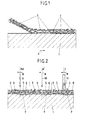
- Fig. 1 einen Schnitt durch einen zu beschichtenden Grundkörper im Zeitpunkt des Aufbringens einer Pulverschicht,
- Fig. 2 einen Schnitt durch einen beschichteten Grundkörper im Zeitpunkt des Aufschmelzens der aufgebrachten Pulverschicht.
- 1 shows a section through a base body to be coated at the time a powder layer is applied,
- Fig. 2 shows a section through a coated base body at the time of melting the applied powder layer.
In Fig. 1 ist ein schematischer Schnitt durch einen zu beschichtenden Grundkörper im Zeitpunkt des Aufbringens einer Pulverschicht dargestellt. 1 stellt einen Grundkörper (Grundwerkstoff, Substrat) dar, welcher mit einer Korrosionsschutzschicht zu versehen ist. Im vorliegenden Fall handelt es sich um einen Ausschnitt aus einem Bauteil für eine thermische Maschine, z.B. aus einer Gasturbinenschaufel bestehend aus einer Nickelbasis-Superlegierung. Die aufzubringende Pulvermischung ist schematisch als Gemenge der Partikel 2 aus einer Superlegierung und der Partikel 3 aus Siliziumkarbid dargestellt. Die Vorschubrichtung des Grundkörpers 1 beim Aufbringen der Pulvermischung ist durch den Pfeil 4 angedeutet.1 shows a schematic section through a base body to be coated at the time a powder layer is applied. 1 represents a base body (base material, substrate) which is to be provided with a corrosion protection layer. In the present case, it is a section of a component for a thermal machine, for example a gas turbine blade consisting of a nickel-based superalloy. The powder mixture to be applied is shown schematically as a mixture of
Das aufzubringende Material ist hier als lose Pulvermischung dargestellt. Doch gilt Fig. 1 grundsätzlich auch für alle anderen derartigen Aufbringverfahren: Einfüllen von Pulver in einen Zwischenraum zwischen Grundkörper 1 und Gesenk oder Kapsel, Auftragen einer Paste mittels Pinsel oder anderer Vorrichtung etc.The material to be applied is shown here as a loose powder mixture. However, Fig. 1 also applies in principle to all other such application methods: pouring powder into a space between the base body 1 and the die or capsule, applying a paste using a brush or other device, etc.
Fig. 2 stellt den schematischen Schnitt durch einen beschichteten Grundkörper im Zeitpunkt des Aufschmelzens der aufgebrachten Pulverschicht dar. Die Bezugszeichen 1 bis 3 entsprechen genau denjenigen der Fig. 1. Daraus geht der Zustand der locker aufgestreuten Pulverpartikel hervor. 5 stellt jeweils die aufgeschmolzene und wieder erstarrte Masse des Superlegierungspulvers dar. Dieser, die Matrix der Korrosionsschutzschicht bildende Teil ist des weiteren fest mit dem Grundkörper 1 durch einen entsprechenden Aufschmelz- und Erstarrungsvorgang verbunden. Die entsprechende Verbindungszone 7 Korrosionsschutzschicht/Grundkörper ist durch eine unregelmässige Linie angedeutet. 6 stellen die in der Masse 5 eingebetteten, zum Teil aufgeschmolzenen bzw. chemisch umgewandelten Siliziumkarbid-Partikel und ihre Umwandlungsprodukte (Komplexe, mehrfache Karbide und Mischkarbide) dar. In der Figur sind 3 verschiedene Aufschmelzverfahren und ihre entsprechenden Mittel dargestellt. 9 bezieht sich auf einen Laserstrahl (gewellte Linie hY), 10 auf einen Elektronenstrahl (punktierte Linie e ) und 11 auf einen Lichtbogen (Stromzuführungselektrode -, Strom I). Die jeweilige Vorschubrichtung des verwendeten Mittels beim Aufschmelzen der Pulvermischung ist durch Pfeile 8 angedeutet.FIG. 2 shows the schematic section through a coated base body at the time of melting the applied powder layer. The reference numerals 1 to 3 correspond exactly to those in FIG. 1. This shows the state of the loosely scattered powder particles. 5 each represents the melted and re-solidified mass of the superalloy powder. This part, which forms the matrix of the corrosion protection layer, is furthermore firmly connected to the base body 1 by a corresponding melting and solidification process. The
Auf eine Gasturbinenschaufel aus einer Nickelbasis-Superlegierung der Markenbezeichnung MA 6000 (Inco) wurde eine Korrosionsschutzschicht aufgebracht. Die Superlegierung hatte folgende Zusammensetzung:

Legierungspulver der gleichen vorstehenden Zusammensetzung wurde im Volumenverhältnis 1:1 mit Siliziumkarbidpulver gemischt: SiC-Gehalt der Pulvermischung ca. 28 Gew.-%; C-Gehalt ca. 8,4 Gew.-%; Si-Gehalt ca. 19,6 Gew.-%. Die Pulvermischung hatte eine mittlere Korngrösse von ca. 60 µm (grösstes Korn ca. 100 µm). Die Gasturbinenschaufel wurde nun derart in das Gesenk einer Schmiedepresse eingelegt, dass allseitig ein Hohlraum von ca. 2 bis 3 mm vorhanden war, welcher von der Pulvermischung ausgefüllt wurde. Die Schaufel war also allseitig im Pulver eingebettet. Nun wurde das Ganze während 5 s bei einer Temperatur von 900°C und einem Druck von 500 MPa isotherm heissgepresst. Dabei verschweissten die Partikel des Legierungspulvers sowohl untereinander wie mit der Masse der Superlegierung der Schaufel zu einem festen, dichten, kompakten Körper, in dessen Randzone die SiC-Partikel eingelagert waren. Letztere hatten teilweise mit dem Superlegierungsmaterial reagiert, so dass ein Austausch der beteiligten Elemente (chemische Umwandlung) stattfand. Durch Analyse wurde ermittelt, dass die Korrosionsschutzschicht, welche eine durchschnittliche Dicke von ca. 1 mm aufwies, im wesentlichen aus einer hochnickelhaltigen Matrix bestand, in welche ein Teil des Siliziums eingewandert war. In dieser Matrix waren verschiedene Partikel von komplexen Phasen eingebettet. Unter anderem wurden Mischkarbide des W, Mo, Cr, Ta und Ti nebst solchen mit unverändertem SiC festgestellt. Sowohl die siliziumhaltige Matrix wie die noch Silizium enthaltenden Karbide dienen im Betrieb als Reserve (Speicher) für die Bildung der SiO2-haltigen Deckschicht.Alloy powder of the same composition above was mixed in a volume ratio of 1: 1 with silicon carbide powder: SiC content of the powder mixture approx. 28% by weight; C content approx. 8.4% by weight; Si content approx. 19.6% by weight. The powder mixture had an average grain size of approx. 60 µm (largest grain approx. 100 µm). The gas turbine blade was then inserted into the die of a forging press in such a way that there was a cavity of approximately 2 to 3 mm on all sides, which was filled by the powder mixture. The blade was therefore embedded in the powder on all sides. The whole was then hot pressed for 5 s at a temperature of 900 ° C. and a pressure of 500 MPa. The particles of the alloy powder welded to each other as well as to the mass of the superalloy of the blade to form a solid, dense, compact body in the edge zone the SiC particles were embedded. The latter had partially reacted with the superalloy material, so that an exchange of the elements involved (chemical conversion) took place. It was determined by analysis that the corrosion protection layer, which had an average thickness of approximately 1 mm, consisted essentially of a matrix containing high nickel, into which part of the silicon had migrated. Various particles of complex phases were embedded in this matrix. Among other things, mixed carbides of W, Mo, Cr, Ta and Ti were found along with those with unchanged SiC. During operation, both the silicon-containing matrix and the carbides still containing silicon serve as a reserve (storage) for the formation of the SiO 2 -containing top layer.
Eine zuvor auf längliches Grobkorn geglühte Gasturbinenschaufel aus der Legierung MA 6000 gemäss Zusammensetzung von Beispiel 1 wurde mit einer Korrosionsschutzschicht versehen. Zunächst wurde Legierungspulver der gleichen Zusammensetzung wie der Grundkörper 1 (Fig. 1) im Volumenverhältnis 1:1 mit Siliziumkarbidpulver gemischt: SiC-Gehalt der Pulvermischung ca. 28 Gew.-%; C-Gehalt ca. 8,4 Gew.-%; Si-Gehalt ca. 19,6 Gew.-%. Die mittlere Korngrösse der Pulvermischung betrug 20µm (grösstes Korn ca. 40 µm). Aus Weicheisenblech von 1 mm Dicke wurde eine Kapsel geformt, deren Hohlmasse (Innenabmessungen) diejenigen der Gasturbinenschaufel um ca. 4 - 5 mm übertrafen: Einseitiger Abstand der Kapselinnenwand von der Schaufeloberfläche ca. 2 - 2,5 mm. Dieser Hohlraum wurde mit der Pulvermischung gefüllt und die Kapsel daraufhin gasdicht verschweisst. Nun wurde das Ganze einem heiss-isostatischen Pressvorgang unter einem Druck von 150 MPa bei einer Temperatur von 1200°C während 1/2 h ausgesetzt. Nach dem Pressen wurde die Weicheisenschicht durch mechanische Bearbeitung entfernt. Es hatte sich darunter eine mit dem Grundkörper 1 fest verschweisste Korrosionsschutzschicht von ca. 1 - 1,2 mm Dicke gebildet, in deren Matrix aus Superlegierung diskrete Partikel von Karbiden eingelagert waren, welche als Speicher für die Oxyd-Deckschicht dienen.A gas turbine blade made of the alloy MA 6000 according to the composition of Example 1 and previously annealed to elongated coarse grain was provided with a corrosion protection layer. First, alloy powder of the same composition as base body 1 (FIG. 1) was mixed with silicon carbide powder in a volume ratio of 1: 1: SiC content of the powder mixture was about 28% by weight; C content approx. 8.4% by weight; Si content approx. 19.6% by weight. The average grain size of the powder mixture was 20 µm (largest grain approx. 40 µm). A capsule was formed from soft iron sheet with a thickness of 1 mm and its hollow mass (internal dimensions) exceeded those of the gas turbine blade by approx. 4 - 5 mm: one-sided distance of the capsule inner wall from the blade surface was approx. 2 - 2.5 mm. This cavity was filled with the powder mixture and the capsule was then sealed gas-tight. Now the whole thing was subjected to a hot isostatic pressing process under a pressure of 150 MPa exposed at a temperature of 1200 ° C for 1/2 h. After pressing, the soft iron layer was removed by mechanical processing. A corrosion protection layer of approximately 1 to 1.2 mm thick, welded to the base body 1, had formed underneath, in whose matrix of superalloy discrete particles of carbides were embedded, which serve as storage for the oxide cover layer.
Auf eine Gasturbinenschaufel der gleichen Legierung MA 6000 wie in Beispiel 1 wurde eine Korrosionsschutzschicht nach dem Pastenverfahren aufgebracht. Legierungspulver (Partikel 2) der gleichen Zusammensetzung wie der Grundkörper 1 wurde im Volumenverhältnis 1:2 mit Siliziumkarbidpulver (Partikel 3) gemischt: SiC-Gehalt der Pulvermischung ca. 44 Gew.-%; C-Gehalt ca. 13,2 Gew.-%; Si-Gehalt ca. 30,8 Gew.-S. Die Pulvermischung hatte eine mittlere Korngrösse von 25 µm (grösstes Korn ca. 40 µm). Diese Pulvermischung wurde in einem organischen Lösungsmittel zu einer Suspension angerührt. Zu diesem Zweck wurden auf 100 g Pulvermischung ca. 50 - 60 ml Terpineol C10H18O gegeben, so dass eine viskose, streichfähige Paste gebildet wurde. Diese Paste wurde in einer Schichtdicke von ca. 2 mm allseitig auf die Gasturbinenschaufel aufgebracht und das Lösungsmittel durch Erhitzen ausgetrieben. Nun wurden die Partikel 2 aus der Superlegierung der aufgetragenen Schicht mittels Laserstrahl 9 von 5 kW Leistung aufgeschmolzen und mit dem Grundkörper 1 in der Verbindungszone 7 als wieder erstarrte Masse 5 fest verankert. Die darin eingebetteten, teilweise umgewandelten Partikel 6 zeigten neben SiC einen gewissen Anteil von komplexen Mischkarbiden. Ein Teil des freigesetzten elementaren Siliziums war in der Matrix der Masse 5 gelöst. Die fertige Korrosionsschutzschicht wies eine Dicke von ca. 0,8 mm auf.A corrosion protection layer was applied to a gas turbine blade of the same MA 6000 alloy as in Example 1 using the paste method. Alloy powder (particle 2) of the same composition as base body 1 was mixed in a volume ratio of 1: 2 with silicon carbide powder (particle 3): SiC content of the powder mixture approx. 44% by weight; C content approx. 13.2% by weight; Si content approx. 30.8% by weight. The powder mixture had an average grain size of 25 µm (largest grain approx. 40 µm). This powder mixture was stirred in an organic solvent to form a suspension. For this purpose, about 50-60 ml of Terpineol C 10 H 18 O were added to 100 g of powder mixture, so that a viscous, spreadable paste was formed. This paste was applied on all sides to the gas turbine blade in a layer thickness of approximately 2 mm and the solvent was expelled by heating. The
Eine Gasturbinenschaufel wurde in der gleichen Weise, wie in Beispiel 3 angegeben, nach dem Pastenverfahren beschichtet. Das Aufschmelzen und Einschmelzen des Legierungspulvers in den Grundkörper 1 erfolgte jedoch mittels eines Elektronenstrahls 10. Das Ergebnis war eine zusammenhängende, fest mit dem Grundkörper 1 verankerte Korrosionsschutzschicht analogen Gefüges und ähnlicher Zusammensetzung wie in Beispiel 2.A gas turbine blade was coated by the paste method in the same manner as in Example 3. However, the alloy powder was melted and melted into the base body 1 by means of an
Als Grundkörper 1 wurde eine Gasturbinenschaufel aus der Legierung MA 6000 gemäss Beispiel 1 verwendet. Die Schaufel wurde zunächst in 10%iger Natronlauge bei 40°C entfettet und dann in 20%iger Schwefelsäure bei Raumtemperatur anodisch gebeizt. Zu diesem Zweck wurde das Werkstück mit dem positiven Pol einer Gleichstromquelle verbunden und in ein Beizbad eingehängt. Nach einer Spülung mit Wasser wurde das Werkstück elektrochemisch mit einer Chromschicht von ca. 0,15 mm Dicke versehen. Nach einer weiteren Spülung wurde das verchromte Werkstück in ein zweites Elektrolysebad gebracht, welches ausser gelösten Nickel- und Borsalzen noch ca. 150 g Siliziumkarbid pro 1 Flüssigkeit in Suspension enthielt. Die Siliziumkarbidpartikel hatten eine Korngrösse von 4 bis 12µm und wurden durch intensive Badbewegung in Schwebe gehalten. Durch einen kombinierten elektrolytisch-elektrophoretischen Prozess wurde dadurch gleichzeitig Nickel (als zusammenhängende Matrix) und Siliziumkarbid (als eingebettete Partikel) auf der Oberfläche des verchromten Grundkörpers 1 in einer Dicke von ca. 0,85 mm abgeschieden. Dabei übernahmen Nickel und Chrom zusammengenommen gleichsam die Funktion der Pulverpartikel 2 und das Siliziumkarbid diejenige der Pulverpartikel 3 in Fig. 1. Die gesamte aufgetragene Oberflächenschicht hatte eine Dicke von ca. 1 mm und wies annähernd die theoretische Dichte auf. In einem darauffolgenden Aufschmelz- und Einschmelzprozess wurde die Schicht mittels Lichtbogen 11 gemäss Fig. 2 wärmebehandelt, wobei eine dem Grundkörper 1 ähnliche Masse 5 als Matrix (Cr/Ni-Legierung) mit eingebetteten Partikeln 6 als zusätzlichem Silizium-Speicher gebildet wurde. Auch hier konnten in der fertigen Korrosionsschutzschicht neben Silizium in der Grundmasse die Karbide des Siliziums, Chroms und in geringerem Gehalt diejenigen des Wolframs, Molybdäns und Tantals sowie entsprechende Mischkarbide festgestellt werden.A gas turbine blade made of the alloy MA 6000 according to Example 1 was used as the base body 1. The scoop was first degreased in 10% sodium hydroxide solution at 40 ° C. and then anodically pickled in 20% sulfuric acid at room temperature. For this purpose, the workpiece was connected to the positive pole of a direct current source and hung in a pickling bath. After rinsing with water, the workpiece was electrochemically provided with a chrome layer of approximately 0.15 mm thick. After a further rinse, the chrome-plated workpiece was placed in a second electrolysis bath which, in addition to dissolved nickel and boron salts, also contained approximately 150 g of silicon carbide per 1 liquid in suspension. The silicon carbide particles had a grain size of 4 to 12 µm and were kept in suspension by intensive bath movement. Through a combined electrolytic-electrophoretic process, nickel (as a coherent matrix) and silicon carbide (as embedded particles) were simultaneously on the surface of the chrome-plated Base body 1 deposited in a thickness of about 0.85 mm. Here, nickel and chromium taken over, as it were, the function of the
Selbstverständlich können die angegebenen Verfahrensschritte mehrmals wiederholt und in der Reihenfolge auch umgekehrt werden. Auch kann die Beimengung des Siliziumkarbidpulvers ebenfalls im Chromelektrolysebad erfolgen. Es können dem Nickelelektrolysebad statt Siliziumkarbid allein auch zusätzlich Silizide, z.B. Chromsilizid Cr3Si als Suspension beigegeben werden. Auf diese Weise lassen sich Oberflächenschichten beliebiger Dicke und Zusammensetzung verwirklichen. Durch den nachfolgenden Auf- und Einschmelzprozess kann die Struktur und Zusammensetzung der Matrix der Oberflächenschicht weitgehend optimiert und der Legierung des Grundkörpers 1 angepasst werden.Of course, the specified process steps can be repeated several times and the order can also be reversed. The silicon carbide powder can also be added in the chromium electrolysis bath. Instead of silicon carbide alone, silicides, for example chromium silicide Cr 3 Si, can also be added to the nickel electrolysis bath as a suspension. In this way, surface layers of any thickness and composition can be realized. The structure and composition of the matrix of the surface layer can be largely optimized and adapted to the alloy of the base body 1 by the subsequent melting and melting process.
Unter gewissen Umständen, insbesondere bei geringeren Anforderungen, geringeren Dicken der Schutzschicht und kleineren Abmessungen des Werkstücks kann auf den ersten Schritt der Verchromung des Grundkörpers 1 verzichtet und mit einem Nickelelektrolysebad allein, mit oder ohne Zusätze von suspendierten chromhaltigen Partikeln (Cr, Cr3Si etc.) gearbeitet werden.Under certain circumstances, in particular with lower requirements, smaller thicknesses of the protective layer and smaller dimensions of the workpiece, the first step of chrome-plating the base body 1 can be omitted and with a nickel electrolysis bath alone, with or without the addition of suspended chromium-containing particles (Cr, Cr 3 Si etc.).
Die Erfindung ist nicht auf die Ausführungsbeispiele beschränkt. Als Aufbringverfahren kann irgend ein Verfahren dienen, welches die gleichzeitige Ablagerung einer metallischen Grundmasse - in Schicht- oder Partikelform - und diskreter SiC-Partikel gewährleistet. Wird hierzu eine Pulvermischung verwendet, so kann die Partikelgrösse vorteilhafterweise 10 bis 100 fm betragen. Arbeitet man nach dem Pastenverfahren, so wird die Pulvermischung in vorteilhafter Weise in einem organischen Lösungsmittel (Terpineol, Dimethylformamid) zu einer viskosen Masse aufgeschlämmt. Im Falle des elektrolytisch/elektrophoretischen Aufbringens können mehrere Bäder hintereinander angewendet werden. Der Verdichtungs/Kompaktierungs/Verschweissungs-Schritt kann durch Aufschmelzen (eine Art lokale Schmelzschweissung) des metallischen Anteils mittels Laserstrahl, Elektronenstrahl oder Lichtbogen oder durch Heisspressen (eine Art Press-Schweissung, Sintern, Drucksintern, Diffusions-Verbinden etc.) erfolgen.The invention is not restricted to the exemplary embodiments. Any method which guarantees the simultaneous deposition of a metallic matrix - in layer or particle form - and discrete SiC particles can serve as the application method. If a powder mixture is used for this purpose, the particle size can advantageously be 10 to 100 μm. If the paste method is used, the powder mixture is advantageously slurried to a viscous mass in an organic solvent (terpineol, dimethylformamide). In the case of electrolytic / electrophoretic application, several baths can be used in succession. The compression / compacting / welding step can be carried out by melting (a kind of local fusion welding) the metallic part using a laser beam, electron beam or electric arc or by hot pressing (a type of press welding, sintering, pressure sintering, diffusion bonding etc.).
Das Heisspressen kann vorteilhafterweise bei einer Temperatur von 900°C und einem Druck von bis 500 MPa während einer Zeitdauer von 0,5 bis 10 s entsprechend einem Verformungsgrad von ca. 0,2 und einer Verformungsgeschwindigkeit von 0,2 10-1s-1 bis 4 ' 10-1s-1 durchgeführt werden. Im Falle der Anwendung des heiss-isostatischen Pressens zur Herstellung der Korrosionsschutzschicht ist es vorteilhaft, von einem zunächst auf Grobkorn geglühten Grundkörper 1 der Gasturbinenschaufel auszugehen und das nachfolgende heiss-isostatische Pressen bei einer Temperatur von 1200°C unter einem Druck von 100 - 150 MPa während einer Zeitdauer von 1/2 bis 3 h durchzuführen. Steht der Grundkörper 1 dagegen lediglich als feinkörniges Vormaterial zur Verfügung, so darf - um eine Rekristallisation in unerwünschter Richtung zu vermeiden - höchstens bei 900°C gepresst werden, was dann Drücke von 500 MPa und Zeiten bis zu 5 h erfordern würde.The hot pressing can advantageously at a temperature of 900 ° C and a pressure of up to 500 MPa for a period of 0.5 to 10 s corresponding to a degree of deformation of about 0.2 and a rate of deformation of 0.2 10 -1 s -1 up to 4 '10 -1 s -1 . If hot-isostatic pressing is used to produce the anti-corrosion layer, it is advantageous to start from a base body 1 of the gas turbine blade that was initially annealed to coarse-grained material, and to then use hot-isostatic pressing at a temperature of 1200 ° C. under a pressure of 100-150 MPa to be carried out for a period of 1/2 to 3 hours. If, on the other hand, the base body 1 is only available as a fine-grained primary material, in order to avoid recrystallization in the undesired direction, pressing may be carried out at a maximum of 900 ° C., which would then require pressures of 500 MPa and times of up to 5 h.
Die Zusammensetzung der metallischen Matrix der Korrosionsschutzschicht kann annähernd die gleiche wie diejenige des Grundkörpers 1 der Gasturbinenschaufel sein. Sie kann ferner aus Nickel, einer Nickel/Chrom-Legierung oder aus Kobalt bestehen. Dieser letztere Fall liegt meist dann vor, wenn der die Matrix bildende Werkstoff elektrochemisch (galvanisch) auf den Grundkörper 1 aufgebracht wird.The composition of the metallic matrix of the corrosion protection layer can be approximately the same as that of the base body 1 of the gas turbine blade. It can also consist of nickel, a nickel / chromium alloy or cobalt. This latter case is usually present when the material forming the matrix is applied electrochemically (galvanically) to the base body 1.
Der Vorteil der neuen Korrosionsschutzschicht besteht darin, dass sie trotz hohen Si-Gehaltes nicht die übliche Sprödigkeit besitzt und im Betrieb nicht vom Grundkörper 1 abblättert. Ausserdem wird eine schnelle Diffusion von Silizium in den Grundkörper 1 verhindert. Das Silizium wandert langsam aus den diskret eingebetteten SiC-Partikeln in die Matrix ein und bildet an der Oberfläche laufend Si02-haltige Deckschichten. Da sich diese Nachlieferung über einen längeren Zeitabschnitt erstreckt kann mit einer hohen Lebensdauer und Wirksamkeit der Korrosionsschutzschicht gerechnet werden.The advantage of the new corrosion protection layer is that, despite the high Si content, it does not have the usual brittleness and does not peel off the base body 1 during operation. In addition, rapid diffusion of silicon into the base body 1 is prevented. The silicon slowly migrates out of the discretely embedded SiC particles into the matrix and continuously forms cover layers containing SiO 2 on the surface. Since this subsequent delivery extends over a longer period of time, a long service life and effectiveness of the corrosion protection layer can be expected.
Claims (10)
Applications Claiming Priority (2)
| Application Number | Priority Date | Filing Date | Title |
|---|---|---|---|
| CH3455/84 | 1984-07-16 | ||
| CH345584 | 1984-07-16 |
Publications (2)
| Publication Number | Publication Date |
|---|---|
| EP0168868A1 true EP0168868A1 (en) | 1986-01-22 |
| EP0168868B1 EP0168868B1 (en) | 1989-02-01 |
Family
ID=4256312
Family Applications (1)
| Application Number | Title | Priority Date | Filing Date |
|---|---|---|---|
| EP85201000A Expired EP0168868B1 (en) | 1984-07-16 | 1985-06-12 | Process for the deposition of a corrosion-inhibiting layer, comprising protective oxide-forming elements at the base of a gas turbine blade, and a corrosion-inhibiting layer |
Country Status (4)
| Country | Link |
|---|---|
| US (1) | US4627896A (en) |
| EP (1) | EP0168868B1 (en) |
| JP (1) | JPS6134107A (en) |
| DE (1) | DE3568065D1 (en) |
Cited By (5)
| Publication number | Priority date | Publication date | Assignee | Title |
|---|---|---|---|---|
| WO1997034076A1 (en) * | 1996-03-13 | 1997-09-18 | Forschungszentrum Karlsruhe Gmbh | Protective coating for tubing blades |
| US6149389A (en) * | 1996-03-13 | 2000-11-21 | Forschungszentrum Karlsruhe Gmbh | Protective coating for turbine blades |
| EP2062997A2 (en) * | 2007-11-23 | 2009-05-27 | MTU Aero Engines GmbH | Device for coating components |
| CN105483696A (en) * | 2015-12-28 | 2016-04-13 | 浙江工业大学 | Method for enhancing surface abrasive resistance of Hastelloy N through laser cladding |
| CN114918628A (en) * | 2022-06-20 | 2022-08-19 | 江苏金通灵鼓风机有限公司 | Manufacturing method of large closed tungsten carbide abrasion-proof impeller |
Families Citing this family (38)
| Publication number | Priority date | Publication date | Assignee | Title |
|---|---|---|---|---|
| CH667108A5 (en) * | 1985-04-22 | 1988-09-15 | Fluehmann Ag Werner | GALVANIC BATHROOM FOR THE COMBINED DEPOSITION OF METAL AND A PERMANENTLY LUBRICATING SOLID LUBRICANT. |
| JPS62254950A (en) * | 1986-04-28 | 1987-11-06 | Fuji Toryo Kogyosho:Kk | Wear resistant model |
| US4802828A (en) * | 1986-12-29 | 1989-02-07 | United Technologies Corporation | Turbine blade having a fused metal-ceramic tip |
| US4735656A (en) * | 1986-12-29 | 1988-04-05 | United Technologies Corporation | Abrasive material, especially for turbine blade tips |
| FR2615871B1 (en) * | 1987-05-26 | 1989-06-30 | Snecma | SUPER-ALLOY TURBOMACHINE PARTS HAVING A METALLOCERAMIC PROTECTIVE COATING |
| US4818833A (en) * | 1987-12-21 | 1989-04-04 | United Technologies Corporation | Apparatus for radiantly heating blade tips |
| US4851188A (en) * | 1987-12-21 | 1989-07-25 | United Technologies Corporation | Method for making a turbine blade having a wear resistant layer sintered to the blade tip surface |
| US4925830A (en) * | 1988-04-14 | 1990-05-15 | Tracer Technologies, Inc. | Laser based method for forming a superconducting oxide layer on various substrates |
| SE463213B (en) * | 1988-05-06 | 1990-10-22 | Ibm Svenska Ab | DEVICE AND PROCEDURE TO ENSURE A METAL SUBSTRATE WITH A RESISTANT SURFACE |
| US4854196A (en) * | 1988-05-25 | 1989-08-08 | General Electric Company | Method of forming turbine blades with abradable tips |
| FR2638781B1 (en) * | 1988-11-09 | 1990-12-21 | Snecma | ELECTROPHORETIC ANTI-WEAR DEPOSITION OF THE CONSOLIDATED METALLOCERAMIC TYPE BY ELECTROLYTIC NICKELING |
| US5211776A (en) * | 1989-07-17 | 1993-05-18 | General Dynamics Corp., Air Defense Systems Division | Fabrication of metal and ceramic matrix composites |
| DE4241420C1 (en) * | 1992-12-09 | 1993-11-25 | Mtu Muenchen Gmbh | Process for the production of components or substrates with composite coatings and its application |
| US5486281A (en) * | 1993-10-15 | 1996-01-23 | United Technologies Corporation | Method for CBN tipping of HPC integrally bladed rotors |
| DE4439950C2 (en) * | 1994-11-09 | 2001-03-01 | Mtu Muenchen Gmbh | Metallic component with a composite coating, use, and method for producing metallic components |
| FR2745589B1 (en) * | 1996-02-29 | 1998-04-30 | Snecma | HIGH STRENGTH-TO-MASS HYBRID PART AND METHOD FOR PRODUCING THE SAME |
| DE19629272A1 (en) * | 1996-07-19 | 1998-01-22 | Abb Patent Gmbh | Method for improving the resistance to crack growth of components made of nickel-based and iron-based materials |
| US6355086B2 (en) * | 1997-08-12 | 2002-03-12 | Rolls-Royce Corporation | Method and apparatus for making components by direct laser processing |
| US5902471A (en) * | 1997-10-01 | 1999-05-11 | United Technologies Corporation | Process for selectively electroplating an airfoil |
| EP1033417A1 (en) * | 1999-03-04 | 2000-09-06 | Siemens Aktiengesellschaft | Process and apparatus for coating a product, especially a high temperature gas turbine component |
| JP2003518193A (en) | 1999-11-16 | 2003-06-03 | トリトン・システムズ・インコーポレイテツド | Laser processing of discontinuous reinforced metal matrix composites |
| AT408351B (en) * | 2000-05-17 | 2001-11-26 | Miba Gleitlager Ag | METHOD FOR GALVANICALLY DEPOSITING A DISPERSION LAYER ON A SURFACE OF A WORKPIECE |
| DE10251902B4 (en) * | 2002-11-07 | 2009-05-07 | Fraunhofer-Gesellschaft zur Förderung der angewandten Forschung e.V. | Process for coating a substrate and coated article |
| US20040188323A1 (en) * | 2003-03-24 | 2004-09-30 | Tzatzov Konstantin K. | Active coating system for reducing or eliminating coke build-up during petrochemical processes |
| DE10337866B4 (en) * | 2003-08-18 | 2014-07-24 | MTU Aero Engines AG | Process for the production of components for gas turbines |
| GB2418208B (en) * | 2004-09-18 | 2007-06-06 | Rolls Royce Plc | Component coating |
| US7799111B2 (en) * | 2005-03-28 | 2010-09-21 | Sulzer Metco Venture Llc | Thermal spray feedstock composition |
| FR2884550B1 (en) * | 2005-04-15 | 2010-09-17 | Snecma Moteurs | PIECE FOR PROTECTING THE EDGE OF A BLADE |
| US7140952B1 (en) | 2005-09-22 | 2006-11-28 | Pratt & Whitney Canada Corp. | Oxidation protected blade and method of manufacturing |
| EP1999288B1 (en) * | 2006-03-20 | 2016-09-14 | Oerlikon Metco (US) Inc. | Method for forming a ceramic containing composite structure |
| US7799388B2 (en) * | 2006-05-26 | 2010-09-21 | Sulzer Metco Venture, Llc | Mechanical seals and method of manufacture |
| DE102006044555A1 (en) * | 2006-09-21 | 2008-04-03 | Mtu Aero Engines Gmbh | repair procedures |
| JP5412462B2 (en) * | 2011-04-19 | 2014-02-12 | 日本パーカライジング株式会社 | Corrosion-resistant alloy coating film for metal material and method for forming the same |
| CN103302285B (en) * | 2013-06-18 | 2015-05-20 | 江苏和昊激光科技有限公司 | Nickel-based metal ceramic alloy powder exclusively used in laser cladding of surface of punch |
| US10471543B2 (en) * | 2015-12-15 | 2019-11-12 | Lawrence Livermore National Security, Llc | Laser-assisted additive manufacturing |
| RU2618027C1 (en) * | 2016-03-28 | 2017-05-02 | Акционерное общество "Научно-производственное объединение "Центральный научно-исследовательский институт технологии машиностроения" АО "НПО "ЦНИИТМАШ" | Pastes for wear-resistant overlaying and wear-resistant coating |
| US20210078107A1 (en) * | 2019-09-12 | 2021-03-18 | The Johns Hopkins University | Reactive additive manufacturing of metallic matrix composites with ceramics |
| RU2755912C1 (en) * | 2021-02-09 | 2021-09-22 | ФЕДЕРАЛЬНОЕ ГОСУДАРСТВЕННОЕ БЮДЖЕТНОЕ ОБРАЗОВАТЕЛЬНОЕ УЧРЕЖДЕНИЕ ВЫСШЕГО ОБРАЗОВАНИЯ "Брянский государственный технический университет" | Carbonizing paste for surface |
Citations (5)
| Publication number | Priority date | Publication date | Assignee | Title |
|---|---|---|---|---|
| US3023490A (en) * | 1955-11-25 | 1962-03-06 | Dawson Armoring Company | Armored metal articles with a thin hard film made in situ and conforming to the exact contour of the underlying surface |
| US3024128A (en) * | 1955-11-14 | 1962-03-06 | Dawson Armoring Company | Method of coating metal article with hard particles |
| DE2115358A1 (en) * | 1970-03-30 | 1971-10-28 | Composite Sciences | Process for the production of layers from finely dispersed filler dispersed in a metal |
| DE2613588A1 (en) * | 1975-04-11 | 1976-10-21 | Eutectic Corp | METHOD OF EXTENDING THE LIFE OF LINE PIPE |
| FR2430286A1 (en) * | 1978-07-04 | 1980-02-01 | Fiat Ricerche | METHOD FOR APPLYING A WEAR RESISTANT MATERIAL TO A METAL SURFACE, FOR EXAMPLE ON A PISTON SEGMENT |
Family Cites Families (11)
| Publication number | Priority date | Publication date | Assignee | Title |
|---|---|---|---|---|
| US3296693A (en) * | 1962-09-21 | 1967-01-10 | Shirley J Carter | Tungsten carbide brazing |
| DE2313104C3 (en) * | 1973-03-16 | 1982-02-18 | Heyes, Josef, Dr.phil., 4000 Düsseldorf | Process for applying a firmly adhering layer of non-metallic substances to an electrically conductive base |
| US3981062A (en) * | 1973-10-01 | 1976-09-21 | Ford Motor Company | Apex seal composition for rotary engines |
| US4079552A (en) * | 1974-11-06 | 1978-03-21 | Fletcher J Lawrence | Diamond bonding process |
| US4288495A (en) * | 1978-05-19 | 1981-09-08 | Ford Motor Company | Article coated with beta silicon carbide and silicon |
| US4241135A (en) * | 1979-02-09 | 1980-12-23 | General Electric Company | Polycrystalline diamond body/silicon carbide substrate composite |
| PL121916B1 (en) * | 1979-08-25 | 1982-06-30 | Przemyslu Narzedziowego Vis K | Method of manufacturing abrasive tools with a metallic galvanic bindereskim gal'vanicheskim vjazhuhhim |
| SE8000750L (en) * | 1980-01-30 | 1981-07-31 | Bulten Kanthal Ab | HEATHOLD FIXED MACHINE COMPONENT AND SET TO MAKE IT |
| GB2101910B (en) * | 1981-07-14 | 1984-09-19 | Westinghouse Electric Corp | Improvements in or relating to thermally protected alloys |
| US4447466A (en) * | 1981-08-14 | 1984-05-08 | General Electric Company | Process for making plasma spray-cast components using segmented mandrels |
| JPS5896863A (en) * | 1981-12-02 | 1983-06-09 | Hitachi Ltd | Heat resisting superalloy for joining and its production |
-
1985
- 1985-06-12 EP EP85201000A patent/EP0168868B1/en not_active Expired
- 1985-06-12 DE DE8585201000T patent/DE3568065D1/en not_active Expired
- 1985-06-27 US US06/749,547 patent/US4627896A/en not_active Expired - Fee Related
- 1985-07-16 JP JP15531985A patent/JPS6134107A/en active Pending
Patent Citations (5)
| Publication number | Priority date | Publication date | Assignee | Title |
|---|---|---|---|---|
| US3024128A (en) * | 1955-11-14 | 1962-03-06 | Dawson Armoring Company | Method of coating metal article with hard particles |
| US3023490A (en) * | 1955-11-25 | 1962-03-06 | Dawson Armoring Company | Armored metal articles with a thin hard film made in situ and conforming to the exact contour of the underlying surface |
| DE2115358A1 (en) * | 1970-03-30 | 1971-10-28 | Composite Sciences | Process for the production of layers from finely dispersed filler dispersed in a metal |
| DE2613588A1 (en) * | 1975-04-11 | 1976-10-21 | Eutectic Corp | METHOD OF EXTENDING THE LIFE OF LINE PIPE |
| FR2430286A1 (en) * | 1978-07-04 | 1980-02-01 | Fiat Ricerche | METHOD FOR APPLYING A WEAR RESISTANT MATERIAL TO A METAL SURFACE, FOR EXAMPLE ON A PISTON SEGMENT |
Cited By (8)
| Publication number | Priority date | Publication date | Assignee | Title |
|---|---|---|---|---|
| WO1997034076A1 (en) * | 1996-03-13 | 1997-09-18 | Forschungszentrum Karlsruhe Gmbh | Protective coating for tubing blades |
| US6149389A (en) * | 1996-03-13 | 2000-11-21 | Forschungszentrum Karlsruhe Gmbh | Protective coating for turbine blades |
| EP2062997A2 (en) * | 2007-11-23 | 2009-05-27 | MTU Aero Engines GmbH | Device for coating components |
| EP2062997A3 (en) * | 2007-11-23 | 2011-05-18 | MTU Aero Engines AG | Device for coating components |
| CN105483696A (en) * | 2015-12-28 | 2016-04-13 | 浙江工业大学 | Method for enhancing surface abrasive resistance of Hastelloy N through laser cladding |
| CN105483696B (en) * | 2015-12-28 | 2018-02-13 | 浙江工业大学 | A kind of method for strengthening Hastelloy N alloy surface wearabilities using laser melting coating |
| CN114918628A (en) * | 2022-06-20 | 2022-08-19 | 江苏金通灵鼓风机有限公司 | Manufacturing method of large closed tungsten carbide abrasion-proof impeller |
| CN114918628B (en) * | 2022-06-20 | 2023-09-15 | 江苏金通灵鼓风机有限公司 | Manufacturing method of large closed tungsten carbide wear-resistant impeller |
Also Published As
| Publication number | Publication date |
|---|---|
| US4627896A (en) | 1986-12-09 |
| JPS6134107A (en) | 1986-02-18 |
| DE3568065D1 (en) | 1989-03-09 |
| EP0168868B1 (en) | 1989-02-01 |
Similar Documents
| Publication | Publication Date | Title |
|---|---|---|
| EP0168868B1 (en) | Process for the deposition of a corrosion-inhibiting layer, comprising protective oxide-forming elements at the base of a gas turbine blade, and a corrosion-inhibiting layer | |
| DE69837619T2 (en) | ELECTRODE BAR FOR SPARKLING, METHOD FOR THE PRODUCTION THEREOF, AND METHOD FOR COATING WITH SUPRASED GRINDING-CONTAINING LAYER | |
| DE2954498C2 (en) | ||
| DE2801016C2 (en) | Article made from a superalloy body with a coating of a powder applied by flame spraying and a process for its production | |
| DE3018563A1 (en) | CORROSION-RESISTANT AMORPH PRECIOUS METAL ALLOYS | |
| DE2919375C2 (en) | Application of a method for producing a laminated body | |
| DE10346281B4 (en) | Method for producing components with a nickel-based alloy and components produced therewith | |
| DE2005774A1 (en) | ||
| DE2018032C3 (en) | Process for the production of carbide hard metal based on WC, TiC and / or TaC | |
| DE2808106C2 (en) | Process for the production of a solid connection between parts made of stainless steel or superalloy | |
| DE19983980B3 (en) | A method for producing a discharge surface treatment electrode, hereinafter obtained discharge surface treatment electrode and use thereof | |
| DE2156440A1 (en) | Process for the production of workpieces from materials with different properties | |
| DE1458275A1 (en) | Process for the production of corrosion-resistant, dense nickel coatings on steel strip | |
| AT393367B (en) | LAYER COMPOSITE MATERIAL, ESPECIALLY FOR SLIDING AND FRICTION ELEMENTS, AND METHOD FOR THE PRODUCTION THEREOF | |
| DE2645414C2 (en) | Titanium anodes for the electrolytic production of manganese dioxide, as well as a process for the production of these anodes | |
| DE2225896C2 (en) | Cemented carbide | |
| DE2649388A1 (en) | CORROSION PROTECTION LAYER FOR HEAT-RESISTANT ALLOYS | |
| DE102010055791A1 (en) | Process for the manufacture of components made of refractory metals | |
| DE2137650A1 (en) | Carbide metal composite and processes for its manufacture | |
| DE1446117C3 (en) | Process for producing a diffusion layer on objects made of alloys | |
| DE3208835A1 (en) | Insoluble electrode and electrochemical apparatus | |
| DE2164738C2 (en) | Process for the aftertreatment of metal-ceramic moldings | |
| DE1927016A1 (en) | Process to increase the service life of tools | |
| DE467247C (en) | Process for the production of metallic beryllium or its alloys | |
| DE1690620C3 (en) | Method of manufacturing an electrical resistance spot welding electrode |
Legal Events
| Date | Code | Title | Description |
|---|---|---|---|
| PUAI | Public reference made under article 153(3) epc to a published international application that has entered the european phase |
Free format text: ORIGINAL CODE: 0009012 |
|
| AK | Designated contracting states |
Designated state(s): CH DE GB LI |
|
| 17P | Request for examination filed |
Effective date: 19860627 |
|
| 17Q | First examination report despatched |
Effective date: 19870522 |
|
| RAP1 | Party data changed (applicant data changed or rights of an application transferred) |
Owner name: BBC BROWN BOVERI AG |
|
| GRAA | (expected) grant |
Free format text: ORIGINAL CODE: 0009210 |
|
| AK | Designated contracting states |
Kind code of ref document: B1 Designated state(s): CH DE GB LI |
|
| REF | Corresponds to: |
Ref document number: 3568065 Country of ref document: DE Date of ref document: 19890309 |
|
| GBT | Gb: translation of ep patent filed (gb section 77(6)(a)/1977) | ||
| PLBE | No opposition filed within time limit |
Free format text: ORIGINAL CODE: 0009261 |
|
| STAA | Information on the status of an ep patent application or granted ep patent |
Free format text: STATUS: NO OPPOSITION FILED WITHIN TIME LIMIT |
|
| 26N | No opposition filed | ||
| PGFP | Annual fee paid to national office [announced via postgrant information from national office to epo] |
Ref country code: CH Payment date: 19900914 Year of fee payment: 6 |
|
| PG25 | Lapsed in a contracting state [announced via postgrant information from national office to epo] |
Ref country code: LI Effective date: 19910630 Ref country code: CH Effective date: 19910630 |
|
| REG | Reference to a national code |
Ref country code: CH Ref legal event code: PL |
|
| PGFP | Annual fee paid to national office [announced via postgrant information from national office to epo] |
Ref country code: GB Payment date: 19930512 Year of fee payment: 9 |
|
| PGFP | Annual fee paid to national office [announced via postgrant information from national office to epo] |
Ref country code: DE Payment date: 19930819 Year of fee payment: 9 |
|
| PG25 | Lapsed in a contracting state [announced via postgrant information from national office to epo] |
Ref country code: GB Effective date: 19940612 |
|
| GBPC | Gb: european patent ceased through non-payment of renewal fee |
Effective date: 19940612 |
|
| PG25 | Lapsed in a contracting state [announced via postgrant information from national office to epo] |
Ref country code: DE Effective date: 19950301 |