EP0168734B1 - Paper loading system for use in a printer - Google Patents
Paper loading system for use in a printer Download PDFInfo
- Publication number
- EP0168734B1 EP0168734B1 EP85108410A EP85108410A EP0168734B1 EP 0168734 B1 EP0168734 B1 EP 0168734B1 EP 85108410 A EP85108410 A EP 85108410A EP 85108410 A EP85108410 A EP 85108410A EP 0168734 B1 EP0168734 B1 EP 0168734B1
- Authority
- EP
- European Patent Office
- Prior art keywords
- paper
- rollers
- carriage
- bail
- loading system
- Prior art date
- Legal status (The legal status is an assumption and is not a legal conclusion. Google has not performed a legal analysis and makes no representation as to the accuracy of the status listed.)
- Expired - Lifetime
Links
Images


Classifications
-
- B—PERFORMING OPERATIONS; TRANSPORTING
- B41—PRINTING; LINING MACHINES; TYPEWRITERS; STAMPS
- B41J—TYPEWRITERS; SELECTIVE PRINTING MECHANISMS, i.e. MECHANISMS PRINTING OTHERWISE THAN FROM A FORME; CORRECTION OF TYPOGRAPHICAL ERRORS
- B41J13/00—Devices or arrangements of selective printing mechanisms, e.g. ink-jet printers or thermal printers, specially adapted for supporting or handling copy material in short lengths, e.g. sheets
- B41J13/10—Sheet holders, retainers, movable guides, or stationary guides
- B41J13/20—Bails
-
- B—PERFORMING OPERATIONS; TRANSPORTING
- B41—PRINTING; LINING MACHINES; TYPEWRITERS; STAMPS
- B41J—TYPEWRITERS; SELECTIVE PRINTING MECHANISMS, i.e. MECHANISMS PRINTING OTHERWISE THAN FROM A FORME; CORRECTION OF TYPOGRAPHICAL ERRORS
- B41J11/00—Devices or arrangements of selective printing mechanisms, e.g. ink-jet printers or thermal printers, for supporting or handling copy material in sheet or web form
- B41J11/0025—Handling copy materials differing in width
- B41J11/003—Paper-size detection, i.e. automatic detection of the length and/or width of copy material
-
- B—PERFORMING OPERATIONS; TRANSPORTING
- B41—PRINTING; LINING MACHINES; TYPEWRITERS; STAMPS
- B41J—TYPEWRITERS; SELECTIVE PRINTING MECHANISMS, i.e. MECHANISMS PRINTING OTHERWISE THAN FROM A FORME; CORRECTION OF TYPOGRAPHICAL ERRORS
- B41J11/00—Devices or arrangements of selective printing mechanisms, e.g. ink-jet printers or thermal printers, for supporting or handling copy material in sheet or web form
- B41J11/0095—Detecting means for copy material, e.g. for detecting or sensing presence of copy material or its leading or trailing end
-
- B—PERFORMING OPERATIONS; TRANSPORTING
- B41—PRINTING; LINING MACHINES; TYPEWRITERS; STAMPS
- B41J—TYPEWRITERS; SELECTIVE PRINTING MECHANISMS, i.e. MECHANISMS PRINTING OTHERWISE THAN FROM A FORME; CORRECTION OF TYPOGRAPHICAL ERRORS
- B41J29/00—Details of, or accessories for, typewriters or selective printing mechanisms not otherwise provided for
- B41J29/42—Scales and indicators, e.g. for determining side margins
Definitions
- the present invention relates to a paper loading system for use in a printer and, more particularly, to a system which may locate the opposite side edges of a loaded paper and automatically move and position the bail rollers along the paper bail to approximately opposite side rims of the loaded paper.
- a paper loading system for use in a printer as disclosed in EP-A-0 012 881 or 0 015 553 comprises a rotable platen for loading a paper thereon and a carriage movable provided adjacent to the platen.
- the right and left edges of the loaded paper are detected by optical detecting means mounted on the carriage and the position of the carriage is stored when the edge detecting means detects an edge of the loaded paper.
- the paper loading system determines the position of the loaded paper by detecting the side edges of the paper.
- a prior art paper loading device with a paper bail is shown.
- the paper loading device includes a platen 40 rotatably supported by a shaft diagrammatically shown by a chain line 41.
- feed rollers 43a, 43b and 43c which are rotatably mounted on a shaft 42 extending parallel to shaft 41.
- Feed rollers 43a, 43b and 43c are held against the platen with a predetermined pressure.
- the paper bail 44 extends parallel to shaft 41 and bail rollers 45a and 45b are rotatably mounted on paper bail 44. By the pushing force, bail rollers 45a and 45b move along paper bail 44.
- bail rollers 45a and 45b are held against the platen with a predetermined pressure by a suitable spring (not shown) so as to hold a paper between the platen and rollers.
- bail rollers 45a and 45b are separated away from the platen so as to release the paper.
- the paper After loading a paper, the paper is advanced to a printing position at which the bail, which has been in the released position, is moved to the pressing position so as to hold the paper.
- the bail rollers should be so organized at positions within the width of the loaded paper, and yet at places where the rollers do not affect the printing, such as at opposite side rims of the loaded paper.
- the printer is a type which uses ink, such as an ink-jet printer
- the proper positioning of the bail rollers is very important. For example, if the bail rollers are positioned away from the loaded paper, the paper may be lifted off from the platen. In such a case, the ink-jet may be spotted on the paper awkwardly, resulting in a deformed charac-* ter. Also, if the bail rollers are positioned against the printing area of the paper, the rollers may run over the characters just printed, resulting in an ink smear or transfer of the ink onto the rollers and back onto the paper.
- the places for positioning the bail rollers are determined by the detection of opposite side edges of the loaded paper, which can be located.
- the paper loading system for use in a printer comprises a platen, a paper bail mounted with at least two rollers, and a carriage provided to move parallelly, to the platen.
- a projection is mounted on the carriage with a photodetector is provided at a free end thereof to detect an edge of a loaded paper so as to memorize the opposite ends of the loaded paper.
- the paper bail When the paper bail is in a pressing position at which rollers are holding the paper on a path of advance of the paper, no engagement is accomplished between the projection and the rollers. But when the paper bail is in a releasing position at which rollers are separated from the path to release the paper, the projection may come into contact with rollers to change the position of rollers.
- the movements of the carriage and the paper bail are controlled to locate the rollers at the opposite side rims of the loaded paper.
- a reference number 1 designates a platen rotatably supported on a printer body (not shown) and 4 is a paper pressing apparatus for pressing the loaded paper onto platen 1.
- Paper pressing apparatus 4 include a paper bail 5 having one end 5a so bent and connected to a shaft of a rotary solenoid 8.
- a spring 14 is connected to bail 5 so as to urge the bail in the direction indicated by an arrow B.
- Mounted on paper bail 5 are bail rollers 6a and 6b and a spacer7 between the two bail rollers. Bail rollers 6a and 6b have the same diameter and spacer 7 has a diameter smaller than that of the bail roller.
- bail rollers 6a and 6b, as well as spacer7 may move along the paper bail. Also, rollers 6a and 6b freely rotate.
- paper bail 5 When solenoid 8 is off, paper bail 5 is rotated in the direction B by spring 14 so as to hold bail rollers 6a and 6b against platen with a predetermined pressure, as indicated by a dotted line. Thus, a paper may be held against the bail. Paper bail 5 in this position is referred to as a pressing position.
- paper bail 5 rotates in the direction opposite to arrow B against the urging force of the spring 14, thereby releasing the paper held between platen 1 and rollers 6a and 6b. Power supply and power cut to solenoid 8 is done by driver 9. Paper bail 5 in this position is referred to as a releasing position.
- a reference number 2 designates a carriage installed with a printing head (not shown), such as an ink jet nozzle which shoots droplets of ink towards platen 1.
- a carriage 2 is movably mounted on a pair of rails 3a and 3b which extend parallel to platen 1, and its movement is terminated at right-and left-end positions by way of software as stored in a memory 28, which will be described later, and also by way of hardware by right- and left-end stoppers (not shown).
- An elongated belt 3c having black and white stripes depicted with a constant narrow pitch extends between rails 3a and 3b.
- a photodetector 3d defined by a light emitting diode and a photocell is provided under carriage 2 so as to produce one pulse when photodetector 3d moves across one stripe. Accordingly, by the detection of number of pulses generated from photodetector 3d, it is possible to detect distance of movement of the carriage. According to a preferred embodiment, photodetector 3d is provided in the same plane, cut perpendicularly to rails 3a and 3b, as that contains probe 10, which will be described below, so that the position of the carriage as monitored by the detection of number of stripes is identical to the position of probe 10. Also, by the detection of rate of generation of pulse, it is possible to detect the speed of the carriage.
- Carriage 2 has a probe 10 extending therefrom, and its free end is located close to a path of advance of the paper, such as adjacent the surface of platen 1.
- probe 10 When paper bail 5 is moved to the released position, as shown by a real line, probe 10 may come in contact with end face of bail roller 6a or 6b so as to push and move the bail roller in accordance with the movement of the carriage 2.
- the free end of probe 10 is provided with a photodetector defined by a light emitting diode 11 for emitting light towards the path of advance of the paper and a photocell 12 for receiving a reflected light (Fig. 3) which are aligned side-by- side vertically, as shown, or horizontally, or in any other angle.
- the photodetector or more particularly photocell 12 Since the reflectivity of paper differs from that of the platen surface, the photodetector, or more particularly photocell 12, generates a signal when it moves past a boundary of the paper loaded on the platen. In place of the photodetector, any other detector may be employed.
- Photodetector 13 is also defined by a light emitting diode and a photocell and is provided for detecting the insertion of a new paper.
- FIG. 4 a block diagram of a controller for controlling the paper loading system of the present invention is shown.
- a central processing unit (CPU) 15 has an interface I/O device and program control memories.
- a memory 16 is coupled to CPU 15 for storing various data as explained below.
- bail rollers 6a and 6b, as well as spacer 7, are in the initial position, bail rollers 6a and 6b and spacer 7 are held together and are positioned at the right-hand end of the paper bail with a narrow space provided between the right-hand end face of right roller 6b and a most right-hand end position so as to permit the insertion of probe 10 in the narrow space therebetween.
- bail rollers 6a and 6b as wel as spacer 7 are first shifted together to the initial position, and then they are separated and shifted to the opposite sides of a loaded paper along the paper bail, in a manner described later.
- a table of various paper sizes such as A3, A4, A5, B3, B4, B5, etc. with a width listed to each size is stored.
- data of right- and left-hand edge positions of the loaded paper are stored.
- the positions of carriage 2 as detected by belt 3c are stored, when probe 10 detects the right- and left-hand edges of the loaded paper.
- the home position is the position from which carriage 2 starts to move for effecting the printing, and is located further rightto the right-hand edge of the loaded paper with the spacing of the approaching distance. Generally, the home position is located close to the right-end position of the scan of carriage 2.
- data representing an appropriate position of carriage 2 for detecting the leading edge of the loaded paper is stored.
- the appropriate position is approximately at the center of platen 1.
- CPU 15 is also coupled with a format setting device 20 which has a plurality of manually operable switches and keys (not shown). When switches and keys are operated, format setting device 20 produces a signal which requests the reorganization of bail rollers. When switches and keys are operated in another manner, format setting device 20 produces another signal which indicates the change of paper size.
- CPU 15 is further coupled with line feeder 19 which controls the driving of platen 1 to advance the loaded paper, solenoid actuator 18 which controls the movement of bail between the pressing position and releasing position, and carriage driver 17 which controls the movement of the carriage 2 along the pair of rails 3a and 3b.
- Fig. 5 showing a time chart of movement of carriage and bail rollers
- Figs. 6a, 6b and 6c showing a flow chart for controlling the carriage movement.
- the system operation is mainly divided into five operations which are: (1) an operation for loading a paper; (2) an operation for detecting paper position and paper size; (3) an operation for moving rollers to the initial position; (4) an operation for moving the rollers to the opposite sides of the loaded paper; and (5) a printing operation.
- Each of these operations are described below.
- step #31 the feeding of a new sheet of paper is detected by the receipt of a paper receipt signal from photodetector 13.
- step #32 it is detected whether or not the size of the paper has been changed; whether or not the inserted position of the paper has been changed; and whether or not the reorganization of rollers is requested.
- a signal is transmitted from format setting device 20 to CPU 15 for the operation following step #33. If no signal is transmitted to CPU 15 from format setting device 20 at step 32, the program goes to step #74 for moving the carriage to home position and thereafter carrying out the printing operation as indicated in steps #68-#73.
- step #33 carriage 2 is moved to the center as stored in memory 27 and, at the same time, platen 1 is further rotated (step #34) to advance the inserted paper.
- step #34 the rotation of platen 1 stops to stop the further advance of the paper, thereby completing the paper loading (step #35).
- carriage 2 is moved to the right-end position, as stored in memory 28, for the preparation of the next operation.
- step #37 From the right-end position, carriage 2 moves towards left (step #37).
- photodetector 3d facing black-and- white striped belt 3c, generates a train of pulses.
- An up-down counter 17' is provided for counting the number of pulses generated from photodetector 3d, so as to locate the position of carriage 2.
- photocell 12 When probe 10 extending from carriage 2 moves past the right side edge of the loaded paper, photocell 12 generates a first pulse (step #38).
- the content of the up-down counter is read for detecting the position of probe 10.
- the detected position which indicates the position of the right side edge of the loaded paper as measured, e.g., from the right-end position, is stored in memory 23 (step #39).
- Carriage 2 further moves towards left. Then, when probe 30 moves past the left side edge of the loaded paper, photocell 12 generates a second pulse (step #401. In response to the second pulse, the content of the up-down counter is read for detecting the position of probe 10. The detected position, which indicates the position of the left side edge of the loaded paper, is stored in memory 23 (step #41).
- carriage 2 further moves left (step #42) until it is terminated at the left-end position as stored in memory 28 (step #43).
- bail 5 which has been in the pressing position, is moved to the released position (step #44) so as to permit the contact between the probe and roller. Then, carriage 2 moves towards right (step #45). During the movement, probe 10 contacts and pushes left roller 6a, which in turn contacts and pushes spacer 7, and which in turn contacts and pushes right roller 6b. The movement of carriage 2 towards right continues until the rollers and spacer are located at the initial position wherein the right end face of right roller 6b is located closely adjacent the right-end position so as to provide a narrow space between the right end face'of right roller 6b and the right-end position (step #46).
- the positioning of the rollers and spacer to the initial position can be done by locating the carriage-at a position which is spaced from the right end position a predetermined distance equal to the sum of the length of rollers and spacer and the width of probe 10.
- step #48 carriage is further moved to the right-end position (step #48) with no contact with rollers and, thereafter, the paper bail is moved to the released position against the biasing force of spring 14 by the actuation of solenoid 8 (step #49). Accordingly, probe 10 is positioned just on the right-hand side of right roller 6b.
- carriage 2 moves towards left so as to move the rollers and spacer together towards left (step #50).
- a distance between carriage 2 (preferably at a point where probe 10 is provided) and right-end position is continuously monitored by counting the stripes on belt 3c.
- the movement of carriage 2 continues until the position of probe 10 coincides with the position of right side edge of the loaded paper as stored in memory 28. This is done by comparing the present position of carriage 2 with the position of right side edge of the loaded paper (step #52).
- rollers are located at such a position that the right end face of right roller 6b is in flush with the right side edge of the loaded paper.
- step #53 the power to solenoid 8 is cut off to move bail 5 to the pressing position, thereby disengaging the rollers from probe 10.
- flag I is set (step #54), and thereafter, carriage 2 is further moved towards left. At this moment, the positioning of right roller 6b is completed.
- the length of right roller 6b is read from memory 24 thereby locating the position of left end face of right roller 6b. This can be done by adding the length of roller 6b to the position of right side edge of the loaded paper as stored in memory 23.
- the position of carriage 2 is compared with the position of left end face of right roller 6b (step #56).
- bail 5 is moved to the released position (step #57), thereby permitting the engagement of probe 10 and left roller 6a.
- the continuous movement of carriage 2 towards left will shift the left roller 6a towards left.
- the length of left roHer 6a is read from memory 24 (step #59), thereby detecting a position where to stop the carriage so as to bring the left end face of left roller 6a in flush with the left side edge of the loaded paper (step #60). This can be done by subtracting the length of roller 6a from the position of left side edge of the loaded paper as stored in memory 23.
- the position of carriage 2 is compared with the detected position (step #61), and when the position of carriage 2 coincides with the detected position, carriage 2 stops and, at the same time, bail 5 is moved to the pressing position (step #62). Thereafter, carriage 2 is moved back to the home position (step #63). At this moment, the positioning of left roller 6a is completed.
- rollers 6a and 6b are moved to the opposite sides of the loaded paper in the above described manner. Since the diameter of spacer 7 is smaller than that roller 6a or 6b, there will be no engagement between probe 10 and spacer 7.
- carriage 2 is moved to the home position.
- the paper size of the loaded paper is detected in the following manner.
- the positions of the right and left side edges of the loaded paper is read out from memory 23, and a difference therebetween is calculated for obtaining a width of the loaded paper (step #64). Then, using the obtained width as the key factor, the paper size of the loaded paper is searched in a table, as stored in memory 22, listing various paper sizes, such as A3, A4, A5, B3, B4, B5, etc., with the paper width thereof (steps #65 and #66). When the paper size having the obtained width is found, a signal representing the detected paper size is produced for use in the further operation.
- a new home position may be detected at a point located on the right hand side of the right side edge of the loaded . paper with a spacing of the approaching distance as stored in memory 25.
- the printing operation starts upon receipt of a print start signal obtained from CPU 15.
- carriage 2 moves towards left (step #68) from the home position, and is accelerated to a predetermined speed when it is moved to the right side edge of the loaded paper (step #69).
- the printing is carried out (step #70) in a known manner.
- the carriage returns back to the home position (step #72) and starts the printing of the next line. Steps #68-#72 are repeated until the printing of one cut paper completes.
- the home position can be located on the left hand side of the loaded paper. Also, the positions can be measured from the left-end position.
- the bail rollers can be positioned automatically at the left and right side margins with high accuracy even when the size of the paper changes.
Description
- The present invention relates to a paper loading system for use in a printer and, more particularly, to a system which may locate the opposite side edges of a loaded paper and automatically move and position the bail rollers along the paper bail to approximately opposite side rims of the loaded paper.
- A paper loading system for use in a printer as disclosed in EP-A-0 012 881 or 0 015 553 comprises a rotable platen for loading a paper thereon and a carriage movable provided adjacent to the platen. The right and left edges of the loaded paper are detected by optical detecting means mounted on the carriage and the position of the carriage is stored when the edge detecting means detects an edge of the loaded paper. The paper loading system determines the position of the loaded paper by detecting the side edges of the paper.
- In Fig. 1, a prior art paper loading device with a paper bail is shown. The paper loading device includes a
platen 40 rotatably supported by a shaft diagrammatically shown by achain line 41. Provided under the platen arefeed rollers shaft 42 extending parallel toshaft 41.Feed rollers paper bail 44 extends parallel toshaft 41 andbail rollers paper bail 44. By the pushing force,bail rollers paper bail 44. - When the bail is moved to a pressing position,
bail rollers bail rollers - After loading a paper, the paper is advanced to a printing position at which the bail, which has been in the released position, is moved to the pressing position so as to hold the paper.
- In this case, the bail rollers should be so organized at positions within the width of the loaded paper, and yet at places where the rollers do not affect the printing, such as at opposite side rims of the loaded paper.
- In the case where the printing is carried out using different size papers, it is necessary to change the position of the bail rollers each time the paper size is changed. This is usually done manually, and is a cumbersome operation. Therefore, sometimes the operator forgets to move the bail rollers to the proper position.
- If the printer is a type which uses ink, such as an ink-jet printer, the proper positioning of the bail rollers is very important. For example, if the bail rollers are positioned away from the loaded paper, the paper may be lifted off from the platen. In such a case, the ink-jet may be spotted on the paper awkwardly, resulting in a deformed charac-* ter. Also, if the bail rollers are positioned against the printing area of the paper, the rollers may run over the characters just printed, resulting in an ink smear or transfer of the ink onto the rollers and back onto the paper.
- Although there are a number of printers equipped with automatic paper feeding apparatus, its advantage is reduced when bail rollers are to be moved manually.
- It is the object of the present invention to provide a paper loading system for use in a printer wherein the bail rollers can be moved automatically to predetermined positions.
- The problem is solved, according to the invention, with the features of Claim 1.
- The places for positioning the bail rollers are determined by the detection of opposite side edges of the loaded paper, which can be located.
- The paper loading system for use in a printer comprises a platen, a paper bail mounted with at least two rollers, and a carriage provided to move parallelly, to the platen. A projection is mounted on the carriage with a photodetector is provided at a free end thereof to detect an edge of a loaded paper so as to memorize the opposite ends of the loaded paper. When the paper bail is in a pressing position at which rollers are holding the paper on a path of advance of the paper, no engagement is accomplished between the projection and the rollers. But when the paper bail is in a releasing position at which rollers are separated from the path to release the paper, the projection may come into contact with rollers to change the position of rollers. Using the memorized data, the movements of the carriage and the paper bail are controlled to locate the rollers at the opposite side rims of the loaded paper.
- These and other objects and features of the present invention will become apparent from the following description taken in conjunction with a preferred embodiment thereof with reference to the accompanying drawings, throughout which like parts are designated by like reference numerals, and in which:
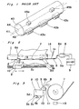
- Fig. 1 is a diagrammatic view of a paper loading system used in a printer, according to the prior art;
- Fig. 2 is a diagrammatic perspective view of a paper loading system according to one embodiment of the present invention;
- Fig. 3 is a diagrammatic side view of a paper loading system of Fig. 2;
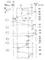
- Fig. 4 is a block diagram of a controller for controlling the paper loading system of the present invention;
- Fig. 5 is a time chart showing the movement of carriage and bail rollers; and
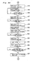
- Figs. 6a, 6b and 6c, taken together as shown in Fig. 6, show a flow chart for controlling the carriage.
- Referring to Fig. 2, a paper loading system according to one preferred embodiment of the present invention is shown. A reference number 1 designates a platen rotatably supported on a printer body (not shown) and 4 is a paper pressing apparatus for pressing the loaded paper onto platen 1.
Paper pressing apparatus 4 include apaper bail 5 having oneend 5a so bent and connected to a shaft of arotary solenoid 8. Aspring 14 is connected tobail 5 so as to urge the bail in the direction indicated by an arrow B. Mounted onpaper bail 5 arebail rollers Bail rollers spacer 7 has a diameter smaller than that of the bail roller. By the application of external force,bail rollers rollers - When
solenoid 8 is off,paper bail 5 is rotated in the direction B byspring 14 so as to holdbail rollers Paper bail 5 in this position is referred to as a pressing position. - When
solenoid 8 is on,paper bail 5 rotates in the direction opposite to arrow B against the urging force of thespring 14, thereby releasing the paper held between platen 1 androllers 6a and 6b. Power supply and power cut tosolenoid 8 is done by driver 9.Paper bail 5 in this position is referred to as a releasing position. - A
reference number 2 designates a carriage installed with a printing head (not shown), such as an ink jet nozzle which shoots droplets of ink towards platen 1. Acarriage 2 is movably mounted on a pair ofrails memory 28, which will be described later, and also by way of hardware by right- and left-end stoppers (not shown). Anelongated belt 3c having black and white stripes depicted with a constant narrow pitch extends betweenrails photodetector 3d defined by a light emitting diode and a photocell is provided undercarriage 2 so as to produce one pulse whenphotodetector 3d moves across one stripe. Accordingly, by the detection of number of pulses generated fromphotodetector 3d, it is possible to detect distance of movement of the carriage. According to a preferred embodiment,photodetector 3d is provided in the same plane, cut perpendicularly torails probe 10, which will be described below, so that the position of the carriage as monitored by the detection of number of stripes is identical to the position ofprobe 10. Also, by the detection of rate of generation of pulse, it is possible to detect the speed of the carriage. - Carriage 2 has a
probe 10 extending therefrom, and its free end is located close to a path of advance of the paper, such as adjacent the surface of platen 1. Whenpaper bail 5 is moved to the released position, as shown by a real line,probe 10 may come in contact with end face ofbail roller carriage 2. The free end ofprobe 10 is provided with a photodetector defined by alight emitting diode 11 for emitting light towards the path of advance of the paper and aphotocell 12 for receiving a reflected light (Fig. 3) which are aligned side-by- side vertically, as shown, or horizontally, or in any other angle. Since the reflectivity of paper differs from that of the platen surface, the photodetector, or more particularlyphotocell 12, generates a signal when it moves past a boundary of the paper loaded on the platen. In place of the photodetector, any other detector may be employed. - As shown in Fig. 3, another
photodetector 13 is provided under platen 1. Photodetector 13 is also defined by a light emitting diode and a photocell and is provided for detecting the insertion of a new paper. - Referring to Fig. 4 a block diagram of a controller for controlling the paper loading system of the present invention is shown.
- A central processing unit (CPU) 15 has an interface I/O device and program control memories. A
memory 16 is coupled toCPU 15 for storing various data as explained below. - At
memory area 21, data representing the initial position of the bail rollers is stored. Whenbail rollers spacer 7, are in the initial position,bail rollers spacer 7 are held together and are positioned at the right-hand end of the paper bail with a narrow space provided between the right-hand end face ofright roller 6b and a most right-hand end position so as to permit the insertion ofprobe 10 in the narrow space therebetween. It is to be noted thatbail rollers spacer 7 are first shifted together to the initial position, and then they are separated and shifted to the opposite sides of a loaded paper along the paper bail, in a manner described later. - At
memory area 22, a table of various paper sizes, such as A3, A4, A5, B3, B4, B5, etc. with a width listed to each size is stored. - At
memory area 23, data of right- and left-hand edge positions of the loaded paper are stored. During the scan ofcarriage 2, the positions ofcarriage 2 as detected bybelt 3c are stored, whenprobe 10 detects the right- and left-hand edges of the loaded paper. - At
memory 24, data of the length of each ofbail rollers spacer 7, as measured in the direction parallel to the paper bail are stored. - At
memory 25, data of an approaching distance necessary to acceleratecarriage 2 from zero to a predetermined constant speed at which the printing is carried out is stored. - At
memory 26, data of a home position ofcarriage 2 is stored. The home position is the position from whichcarriage 2 starts to move for effecting the printing, and is located further rightto the right-hand edge of the loaded paper with the spacing of the approaching distance. Generally, the home position is located close to the right-end position of the scan ofcarriage 2. - At
memory 27, data representing an appropriate position ofcarriage 2 for detecting the leading edge of the loaded paper is stored. According to the preferred embodiment, the appropriate position is approximately at the center of platen 1. - Finally, at
memory 28, data of right- and left-end positions for limiting the movement ofcarriage 2 are stored. -
CPU 15 is also coupled with aformat setting device 20 which has a plurality of manually operable switches and keys (not shown). When switches and keys are operated,format setting device 20 produces a signal which requests the reorganization of bail rollers. When switches and keys are operated in another manner,format setting device 20 produces another signal which indicates the change of paper size. -
CPU 15 is further coupled withline feeder 19 which controls the driving of platen 1 to advance the loaded paper,solenoid actuator 18 which controls the movement of bail between the pressing position and releasing position, andcarriage driver 17 which controls the movement of thecarriage 2 along the pair ofrails - Next, the operation of the paper loading system according to the present invention will be described in connection with Fig. 5 showing a time chart of movement of carriage and bail rollers, and Figs. 6a, 6b and 6c showing a flow chart for controlling the carriage movement.
- The system operation is mainly divided into five operations which are: (1) an operation for loading a paper; (2) an operation for detecting paper position and paper size; (3) an operation for moving rollers to the initial position; (4) an operation for moving the rollers to the opposite sides of the loaded paper; and (5) a printing operation. Each of these operations are described below.
- When a new sheet of paper is fed into a space behind platen 1, platen 1 rotates to roll the paper around platen 1. At
step # 31, the feeding of a new sheet of paper is detected by the receipt of a paper receipt signal fromphotodetector 13. - Then, at
step # 32, it is detected whether or not the size of the paper has been changed; whether or not the inserted position of the paper has been changed; and whether or not the reorganization of rollers is requested. When the paper size is changed, when the inserted position of the paper is changed, or when the reorganization of rollers is requested, a signal is transmitted fromformat setting device 20 toCPU 15 for the operation followingstep # 33. If no signal is transmitted toCPU 15 fromformat setting device 20 atstep 32, the program goes to step #74 for moving the carriage to home position and thereafter carrying out the printing operation as indicated in steps #68-#73. - At
step # 33,carriage 2 is moved to the center as stored inmemory 27 and, at the same time, platen 1 is further rotated (step #34) to advance the inserted paper. When the leading edge of the inserted paper is detected by the photodetector defined by light emittingdiode 11 andphotocell 12, the rotation of platen 1 stops to stop the further advance of the paper, thereby completing the paper loading (step #35). Then,carriage 2 is moved to the right-end position, as stored inmemory 28, for the preparation of the next operation. - From the right-end position,
carriage 2 moves towards left (step #37). During the movement ofcarriage 2,photodetector 3d, facing black-and- whitestriped belt 3c, generates a train of pulses. An up-down counter 17' is provided for counting the number of pulses generated fromphotodetector 3d, so as to locate the position ofcarriage 2. Then, whenprobe 10 extending fromcarriage 2 moves past the right side edge of the loaded paper,photocell 12 generates a first pulse (step #38). In response to the first pulse fromphotocell 12, the content of the up-down counter is read for detecting the position ofprobe 10. The detected position, which indicates the position of the right side edge of the loaded paper as measured, e.g., from the right-end position, is stored in memory 23 (step #39). -
Carriage 2 further moves towards left. Then, when probe 30 moves past the left side edge of the loaded paper,photocell 12 generates a second pulse (step #401. In response to the second pulse, the content of the up-down counter is read for detecting the position ofprobe 10. The detected position, which indicates the position of the left side edge of the loaded paper, is stored in memory 23 (step #41). - Thereafter,
carriage 2 further moves left (step #42) until it is terminated at the left-end position as stored in memory 28 (step #43). - By the detection of positions of the opposite sides of the loaded paper, the paper loaded position and paper width are detected.
- After
carriage 2 is terminated at the left-end position,bail 5, which has been in the pressing position, is moved to the released position (step #44) so as to permit the contact between the probe and roller. Then,carriage 2 moves towards right (step #45). During the movement, probe 10 contacts and pushes leftroller 6a, which in turn contacts and pushesspacer 7, and which in turn contacts and pushesright roller 6b. The movement ofcarriage 2 towards right continues until the rollers and spacer are located at the initial position wherein the right end face ofright roller 6b is located closely adjacent the right-end position so as to provide a narrow space between the right end face'ofright roller 6b and the right-end position (step #46). - The positioning of the rollers and spacer to the initial position can be done by locating the carriage-at a position which is spaced from the right end position a predetermined distance equal to the sum of the length of rollers and spacer and the width of
probe 10. - When the rollers are shifted to the initial position, a power to
solenoid 8 is cut off to permit the rotation ofbail 5 to the pressing position by the urging force of spring 14 (step #47). Accordingly probe 10 is freed from rollers. - Then, carriage is further moved to the right-end position (step #48) with no contact with rollers and, thereafter, the paper bail is moved to the released position against the biasing force of
spring 14 by the actuation of solenoid 8 (step #49). Accordingly,probe 10 is positioned just on the right-hand side ofright roller 6b. - From the right-end position,
carriage 2 moves towards left so as to move the rollers and spacer together towards left (step #50). During the movement, a distance between carriage 2 (preferably at a point whereprobe 10 is provided) and right-end position is continuously monitored by counting the stripes onbelt 3c. The movement ofcarriage 2 continues until the position ofprobe 10 coincides with the position of right side edge of the loaded paper as stored inmemory 28. This is done by comparing the present position ofcarriage 2 with the position of right side edge of the loaded paper (step #52). When thecarriage 2 is so moved to a position at whichprobe 10 coincides with the position of right side edge of the loaded paper, rollers are located at such a position that the right end face ofright roller 6b is in flush with the right side edge of the loaded paper. - Then, at the next step (step #53), the power to
solenoid 8 is cut off to movebail 5 to the pressing position, thereby disengaging the rollers fromprobe 10. At this moment, flag I is set (step #54), and thereafter,carriage 2 is further moved towards left. At this moment, the positioning ofright roller 6b is completed. - During the movement of
carriage 2 towards left, the length ofright roller 6b is read frommemory 24 thereby locating the position of left end face ofright roller 6b. This can be done by adding the length ofroller 6b to the position of right side edge of the loaded paper as stored inmemory 23. The position ofcarriage 2 is compared with the position of left end face ofright roller 6b (step #56). Whencarriage 2 has moved past the left end face ofroller 6b,bail 5 is moved to the released position (step #57), thereby permitting the engagement ofprobe 10 and leftroller 6a. Thus, the continuous movement ofcarriage 2 towards left will shift theleft roller 6a towards left. - In the meantime, the length of left
roHer 6a is read from memory 24 (step #59), thereby detecting a position where to stop the carriage so as to bring the left end face ofleft roller 6a in flush with the left side edge of the loaded paper (step #60). This can be done by subtracting the length ofroller 6a from the position of left side edge of the loaded paper as stored inmemory 23. The position ofcarriage 2 is compared with the detected position (step #61), and when the position ofcarriage 2 coincides with the detected position,carriage 2 stops and, at the same time,bail 5 is moved to the pressing position (step #62). Thereafter,carriage 2 is moved back to the home position (step #63). At this moment, the positioning ofleft roller 6a is completed. -
Rollers spacer 7 is smaller than thatroller probe 10 andspacer 7. - Thereafter,
carriage 2 is moved to the home position. Before the operation proceeds to the printing operation, the paper size of the loaded paper is detected in the following manner. - The positions of the right and left side edges of the loaded paper is read out from
memory 23, and a difference therebetween is calculated for obtaining a width of the loaded paper (step #64). Then, using the obtained width as the key factor, the paper size of the loaded paper is searched in a table, as stored inmemory 22, listing various paper sizes, such as A3, A4, A5, B3, B4, B5, etc., with the paper width thereof (steps # 65 and #66). When the paper size having the obtained width is found, a signal representing the detected paper size is produced for use in the further operation. - In the case where the paper is loaded at any place between the right- and left-end positions by the manual paper feeding, a new home position may be detected at a point located on the right hand side of the right side edge of the loaded . paper with a spacing of the approaching distance as stored in
memory 25. By setting a new home position each time when the paper is loaded manually, the margins of the paper can be maintained constant even if the loaded position differs. When the new home position is detected, the carriage is moved to the new home position. - The printing operation starts upon receipt of a print start signal obtained from
CPU 15. When the print start signal is generated,carriage 2 moves towards left (step #68) from the home position, and is accelerated to a predetermined speed when it is moved to the right side edge of the loaded paper (step #69). Thereafter, the printing is carried out (step #70) in a known manner. When one line is printed, the carriage returns back to the home position (step #72) and starts the printing of the next line. Steps #68-#72 are repeated until the printing of one cut paper completes. - In the above described embodiment, the home position can be located on the left hand side of the loaded paper. Also, the positions can be measured from the left-end position.
- Instead of providing the spacer independently, it is possible to provide a spacer integrally on one or both ends of at least on one roller.
- According to the present invention, since the left and right side edges of the loaded paper are detected, the bail rollers can be positioned automatically at the left and right side margins with high accuracy even when the size of the paper changes.
- Although the present invention has been fully described with reference to a preferred embodiment, many modifications and variations thereof will now be apparent to those skilled in the art, and the scope of the present invention is therefore to be limited not by the details of the preferred embodiment described above, but only by the terms of the appended claims.
Claims (13)
characterized in that,
Applications Claiming Priority (10)
| Application Number | Priority Date | Filing Date | Title |
|---|---|---|---|
| JP14308584A JPS6120776A (en) | 1984-07-09 | 1984-07-09 | Controlling sysem of paper feeding in printer |
| JP143085/84 | 1984-07-09 | ||
| JP59143084A JPS6120780A (en) | 1984-07-09 | 1984-07-09 | Detection of width of printer recording paper |
| JP143084/84 | 1984-07-09 | ||
| JP143083/84 | 1984-07-09 | ||
| JP14308284A JPS6120778A (en) | 1984-07-09 | 1984-07-09 | Paper holding roller position setting device for printer |
| JP14308384A JPS6120779A (en) | 1984-07-09 | 1984-07-09 | Paper holding roller positioning device of printer |
| JP143082/84 | 1984-07-09 | ||
| JP143975/84 | 1984-07-10 | ||
| JP14397584A JPH0238388B2 (en) | 1984-07-10 | 1984-07-10 | PURINTANOHOOMUHOJISHONSETSUTEISOCHI |
Publications (3)
| Publication Number | Publication Date |
|---|---|
| EP0168734A2 EP0168734A2 (en) | 1986-01-22 |
| EP0168734A3 EP0168734A3 (en) | 1987-08-05 |
| EP0168734B1 true EP0168734B1 (en) | 1990-03-07 |
Family
ID=27527665
Family Applications (1)
| Application Number | Title | Priority Date | Filing Date |
|---|---|---|---|
| EP85108410A Expired - Lifetime EP0168734B1 (en) | 1984-07-09 | 1985-07-06 | Paper loading system for use in a printer |
Country Status (4)
| Country | Link |
|---|---|
| US (1) | US4647239A (en) |
| EP (1) | EP0168734B1 (en) |
| CA (1) | CA1254850A (en) |
| DE (1) | DE3576300D1 (en) |
Families Citing this family (16)
| Publication number | Priority date | Publication date | Assignee | Title |
|---|---|---|---|---|
| US5019840A (en) * | 1984-03-30 | 1991-05-28 | Canon Kabushiki Kaisha | Recording apparatus with improved sheet feeding |
| JPH0764101B2 (en) * | 1985-11-09 | 1995-07-12 | 富士通株式会社 | Line feed method and single-cut set device in printer |
| US4795070A (en) * | 1986-08-26 | 1989-01-03 | Eastman Kodak Company | Web tracking apparatus |
| DE69010723T2 (en) * | 1989-03-10 | 1995-03-23 | Fujitsu Ltd | Printer with a mechanism for opening and closing the bracket. |
| JP2545464B2 (en) * | 1989-05-31 | 1996-10-16 | 富士通株式会社 | Printing equipment |
| JPH0342262A (en) * | 1989-07-08 | 1991-02-22 | Brother Ind Ltd | Printer |
| US5182861A (en) * | 1989-08-29 | 1993-02-02 | Mutoh Industries Ltd. | Sheet-driven type automatic drafting machine |
| DE69316475T2 (en) * | 1992-08-11 | 1998-08-27 | Agfa Gevaert Nv | Photographic processor |
| JP2990476B2 (en) * | 1993-05-11 | 1999-12-13 | セイコーインスツルメンツ株式会社 | Printer device |
| JPH0752490A (en) * | 1993-08-10 | 1995-02-28 | Seiko Epson Corp | Controlling method for carriage and paper feeder of printer |
| US5466079A (en) * | 1995-01-27 | 1995-11-14 | Hewlett-Packard Company | Apparatus for detecting media leading edge and method for substantially eliminating pick skew in a media handling subsystem |
| JP2000062974A (en) * | 1998-08-20 | 2000-02-29 | Canon Inc | Sheet material feeding device and recording device |
| US6447089B1 (en) | 2000-10-13 | 2002-09-10 | Hewlett-Packard Company | Techniques for using a linear array to detect media top/bottom edges for full bleed printing |
| JP2003320662A (en) * | 2002-02-28 | 2003-11-11 | Sharp Corp | Imaging apparatus |
| JP4532989B2 (en) * | 2003-06-12 | 2010-08-25 | キヤノン株式会社 | Image forming apparatus |
| AU2011287854B2 (en) | 2010-08-05 | 2015-05-28 | Société des Produits Nestlé S.A. | Cooking aid |
Family Cites Families (12)
| Publication number | Priority date | Publication date | Assignee | Title |
|---|---|---|---|---|
| DK104238C (en) * | 1964-04-18 | 1966-04-25 | Zeuthen & Aagaard As | Duplicator with adjustment mechanisms for width adjustment. |
| US3834505A (en) * | 1972-12-11 | 1974-09-10 | Ibm | Ink jet printing apparatus with line sweep and incremental printing facilities |
| US4050564A (en) * | 1973-11-23 | 1977-09-27 | International Business Machines Corporation | Electronic control for optimizing carrier turnaround in printing apparatus |
| JPS51145324A (en) * | 1975-06-10 | 1976-12-14 | Ricoh Co Ltd | Pressure regulating device for reproduction machine |
| US4265556A (en) * | 1978-12-21 | 1981-05-05 | International Business Machines Corporation | Apparatus for setting proportional margins based upon the width of a scanned sheet of paper |
| US4272204A (en) * | 1978-12-21 | 1981-06-09 | International Business Machines Corporation | Automatic margin determining apparatus for a scanned sheet of paper |
| AU5620080A (en) * | 1979-03-07 | 1980-10-30 | Vydec Inc. | Determining position of paper in typewriter |
| JPS56166087A (en) * | 1980-05-27 | 1981-12-19 | Sharp Corp | Printing system |
| JPS57105381A (en) * | 1980-12-23 | 1982-06-30 | Copal Co Ltd | Printer |
| JPS57140181A (en) * | 1981-02-25 | 1982-08-30 | Usac Electronics Ind Co Ltd | Setting of paper width for printer |
| JPS5831788A (en) * | 1981-08-18 | 1983-02-24 | Ricoh Co Ltd | Printing position controller for printer |
| JPS5836477A (en) * | 1981-08-26 | 1983-03-03 | Fujitsu Ltd | Paper propriety detection system |
-
1985
- 1985-07-06 EP EP85108410A patent/EP0168734B1/en not_active Expired - Lifetime
- 1985-07-06 DE DE8585108410T patent/DE3576300D1/en not_active Expired - Lifetime
- 1985-07-08 US US06/752,856 patent/US4647239A/en not_active Expired - Lifetime
- 1985-07-09 CA CA000486551A patent/CA1254850A/en not_active Expired
Non-Patent Citations (3)
| Title |
|---|
| PATENT ABSTRACTS OF JAPAN, unexamined applications, field M, vol. 6, no. 199, October 8, 1982, Kokai-no. 67-105 381 (COPAL) * |
| PATENT ABSTRACTS OF JAPAN, unexamined applications, field M, vol. 7, no. 63, March 16,1983, Kokai-no. 57-207 078 (TOKYO SHIBAURA DENKI) * |
| PATENT ABSTRACTS OF JAPAN, unexamined applications, field M, vol.7, no. 37, February 15, 1983, Kokai-no. 57-187 286 (MATSUSHITA) * |
Also Published As
| Publication number | Publication date |
|---|---|
| US4647239A (en) | 1987-03-03 |
| CA1254850A (en) | 1989-05-30 |
| EP0168734A2 (en) | 1986-01-22 |
| DE3576300D1 (en) | 1990-04-12 |
| EP0168734A3 (en) | 1987-08-05 |
Similar Documents
| Publication | Publication Date | Title |
|---|---|---|
| EP0168734B1 (en) | Paper loading system for use in a printer | |
| EP1080927B1 (en) | Method and apparatus for processing recording media having embedded information | |
| US6435641B1 (en) | Media movement apparatus | |
| US4565462A (en) | Paper loading apparatus for printer including plural feed paths | |
| US5474392A (en) | Device for automatically detecting thickness of printing sheet in a printer | |
| US4500219A (en) | Method and apparatus for guiding the paper in typewriters or similar office machines | |
| JP2717491B2 (en) | Printer operation method | |
| JP3805174B2 (en) | Recording medium trailing edge detection method and recording apparatus | |
| JPH0421482A (en) | Printer with paper width detector | |
| JPS6120780A (en) | Detection of width of printer recording paper | |
| JPH0422668A (en) | Printer fitted with paper width detector | |
| JPH0651411B2 (en) | Printer device | |
| US4603987A (en) | Recording member pressing device in a printer | |
| GB1565189A (en) | Printer | |
| JPH11157154A (en) | Passbook/slip printer | |
| JPH0226686Y2 (en) | ||
| JPH0289669A (en) | Printer control system | |
| JPH09141962A (en) | Printer and control method therefor | |
| JPH06201412A (en) | Recording roll paper | |
| KR0147577B1 (en) | Printer | |
| JPH0422667A (en) | Printer fitted with paper width detector | |
| JPH02137956A (en) | Paper feed position regulating device of printer | |
| JPH05138999A (en) | Sheet skew detection of printing device | |
| JPH0238388B2 (en) | PURINTANOHOOMUHOJISHONSETSUTEISOCHI | |
| JPH1035977A (en) | Sheet carrying mechanism and ink jet printer |
Legal Events
| Date | Code | Title | Description |
|---|---|---|---|
| PUAI | Public reference made under article 153(3) epc to a published international application that has entered the european phase |
Free format text: ORIGINAL CODE: 0009012 |
|
| AK | Designated contracting states |
Designated state(s): DE GB |
|
| 17P | Request for examination filed |
Effective date: 19861231 |
|
| PUAL | Search report despatched |
Free format text: ORIGINAL CODE: 0009013 |
|
| AK | Designated contracting states |
Kind code of ref document: A3 Designated state(s): DE GB |
|
| 17Q | First examination report despatched |
Effective date: 19881128 |
|
| GRAA | (expected) grant |
Free format text: ORIGINAL CODE: 0009210 |
|
| AK | Designated contracting states |
Kind code of ref document: B1 Designated state(s): DE GB |
|
| REF | Corresponds to: |
Ref document number: 3576300 Country of ref document: DE Date of ref document: 19900412 |
|
| PLBE | No opposition filed within time limit |
Free format text: ORIGINAL CODE: 0009261 |
|
| STAA | Information on the status of an ep patent application or granted ep patent |
Free format text: STATUS: NO OPPOSITION FILED WITHIN TIME LIMIT |
|
| 26N | No opposition filed | ||
| PGFP | Annual fee paid to national office [announced via postgrant information from national office to epo] |
Ref country code: GB Payment date: 19980629 Year of fee payment: 14 |
|
| PGFP | Annual fee paid to national office [announced via postgrant information from national office to epo] |
Ref country code: DE Payment date: 19980904 Year of fee payment: 14 |
|
| PG25 | Lapsed in a contracting state [announced via postgrant information from national office to epo] |
Ref country code: GB Free format text: LAPSE BECAUSE OF NON-PAYMENT OF DUE FEES Effective date: 19990706 |
|
| GBPC | Gb: european patent ceased through non-payment of renewal fee |
Effective date: 19990706 |
|
| PG25 | Lapsed in a contracting state [announced via postgrant information from national office to epo] |
Ref country code: DE Free format text: LAPSE BECAUSE OF NON-PAYMENT OF DUE FEES Effective date: 20000503 |