EP0168501A1 - Area machining method - Google Patents
Area machining method Download PDFInfo
- Publication number
- EP0168501A1 EP0168501A1 EP19850900733 EP85900733A EP0168501A1 EP 0168501 A1 EP0168501 A1 EP 0168501A1 EP 19850900733 EP19850900733 EP 19850900733 EP 85900733 A EP85900733 A EP 85900733A EP 0168501 A1 EP0168501 A1 EP 0168501A1
- Authority
- EP
- European Patent Office
- Prior art keywords
- area
- centroid
- partitioning
- cutting
- curve
- Prior art date
- Legal status (The legal status is an assumption and is not a legal conclusion. Google has not performed a legal analysis and makes no representation as to the accuracy of the status listed.)
- Granted
Links
- 238000000034 method Methods 0.000 title claims abstract description 39
- 238000003754 machining Methods 0.000 title abstract description 7
- 238000005192 partition Methods 0.000 claims abstract description 13
- 238000005520 cutting process Methods 0.000 claims description 105
- 238000000638 solvent extraction Methods 0.000 claims description 26
- 102100024853 Carnitine O-palmitoyltransferase 2, mitochondrial Human genes 0.000 description 7
- 101000909313 Homo sapiens Carnitine O-palmitoyltransferase 2, mitochondrial Proteins 0.000 description 7
- 101000859570 Homo sapiens Carnitine O-palmitoyltransferase 1, liver isoform Proteins 0.000 description 4
- 101000989606 Homo sapiens Cholinephosphotransferase 1 Proteins 0.000 description 4
- 235000010044 Hernandia moerenhoutiana Nutrition 0.000 description 2
- 244000084296 Hernandia moerenhoutiana Species 0.000 description 2
- 238000010586 diagram Methods 0.000 description 2
- 230000006870 function Effects 0.000 description 1
- 230000005291 magnetic effect Effects 0.000 description 1
- 238000003801 milling Methods 0.000 description 1
- 208000010376 orofacial cleft 2 Diseases 0.000 description 1
- 230000002035 prolonged effect Effects 0.000 description 1
Images


Classifications
-
- G—PHYSICS
- G05—CONTROLLING; REGULATING
- G05B—CONTROL OR REGULATING SYSTEMS IN GENERAL; FUNCTIONAL ELEMENTS OF SUCH SYSTEMS; MONITORING OR TESTING ARRANGEMENTS FOR SUCH SYSTEMS OR ELEMENTS
- G05B19/00—Programme-control systems
- G05B19/02—Programme-control systems electric
- G05B19/18—Numerical control [NC], i.e. automatically operating machines, in particular machine tools, e.g. in a manufacturing environment, so as to execute positioning, movement or co-ordinated operations by means of programme data in numerical form
- G05B19/41—Numerical control [NC], i.e. automatically operating machines, in particular machine tools, e.g. in a manufacturing environment, so as to execute positioning, movement or co-ordinated operations by means of programme data in numerical form characterised by interpolation, e.g. the computation of intermediate points between programmed end points to define the path to be followed and the rate of travel along that path
-
- G—PHYSICS
- G05—CONTROLLING; REGULATING
- G05B—CONTROL OR REGULATING SYSTEMS IN GENERAL; FUNCTIONAL ELEMENTS OF SUCH SYSTEMS; MONITORING OR TESTING ARRANGEMENTS FOR SUCH SYSTEMS OR ELEMENTS
- G05B2219/00—Program-control systems
- G05B2219/30—Nc systems
- G05B2219/49—Nc machine tool, till multiple
- G05B2219/49381—Raster, line servo, area machining, cutting, facing
-
- G—PHYSICS
- G05—CONTROLLING; REGULATING
- G05B—CONTROL OR REGULATING SYSTEMS IN GENERAL; FUNCTIONAL ELEMENTS OF SUCH SYSTEMS; MONITORING OR TESTING ARRANGEMENTS FOR SUCH SYSTEMS OR ELEMENTS
- G05B2219/00—Program-control systems
- G05B2219/30—Nc systems
- G05B2219/49—Nc machine tool, till multiple
- G05B2219/49392—Multipasses, segmentation of cut, paraxial cutting
Definitions
- This invention relates to an area cutting method in a numerically controlled machine tool and, more particularly, to an area cutting method for cutting the interior of an area bounded by the curve of an external shape.
- Forms of numerically controlled machining include cutting in which the interior of an area bounded by the curve of an external shape, for example the curve of an external shape comprising straight lines and circular arcs, is hollowed out down to a predetermined depth, and die milling in which the interior of an area is die milled. In such machining, as shown in Fig.
- an area cutting method is conventionally carried out by performing cutting along an (i-l)th cutting path PTi-1 in one direction (the direction of the solid line arrow), raising the tool a predetermined amount at the completion of cutting, then positioning the tool directly above a cutting starting point Ps on the next, or i-th, cutting path PTi, thereafter lowering the tool to the cutting starting point P s, moving the tool along the i-th cutting path PTi in the direction of the solid line arrow, and subsequently repeating the above unidirectional cutting.
- FIG. l(B) Another area cutting method shown in Fig. l(B) includes, following completion of cutting along the cutting path PTi-1 of the (i-l)th cutting path, moving the tool from a cutting end point Pe to the cutting starting point Ps on the next, or i-th, cutting path, and thereafter performing cutting along the i-th cutting path PTi.
- cutting is performed back and forth in the direction of the arrows.
- Still another area cutting method shown in Fig. l(C) includes obtaining offset paths OFCl, OFC2,... OFCn offset by predetermined amounts with respect to a curve OLC of an external shape, and moving the tool successively along the offset paths.
- the tool must be positioned at the cutting starting point Ps on the i-th cutting path PTi after the completion of cutting along the (i-l)th cutting path PTi-1.
- This method is disadvantageous in that it results in a long tool travelling distance.
- the cutting processes referred to here indicate up cutting and down cutting processes.
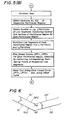
- Figs. 2(A), (B) show examples of the down cutting process
- Figs. 2(C), (D) depict exampes of the up cutting process. If the workpiece material has been decided, then a cutting method capable of cutting the workpiece efficiently is selected from the up cutting and down cutting processes. However, with the second method, the up cutting process [e.g., Fig. 2(A)] and the down cutting process [e.g., Fig. 2(C)] are always mixed, so that cutting cannot be performed efficiently.
- portions are left uncut at, e.g., the central portion of the area, depending upon the contour of the external shape curve.
- This method is disadvantageous in that dealing with these uncut portions is a complicated task.
- an object of the present invention is to provide an area cutting method whereby the interior of an area can be cut continuously and efficiently without requiring control for raising a tool, positioning the tool at the next cutting starting point and then lowering the tool.
- Another object of the present invention is to provide an area cutting method wherein portions are not left uncut.
- An area cutting method for cutting the interior of an area bounded by a closed curve has a step of calculating a centroid of an area bounded by a closed curve, a step of determining whether each line segment connecting the centroid with each vertex of the area intersects the closed curve, a step of partitioning each line segment into a predetermined number of partitions if the line segment does not intersect the closed curve, a step of performing area cutting by moving a tool along plural closed paths each of which is obtained by connecting corresponding ones of the partitioning points of respective line segments, and a step, which is executed if at least one line segment intersects the closed curve, of partitioning the area into a plurality of regions, calculating the centroid of each partitioned region, partitioning each line segment connecting the centroid with each vertex of the partitioned region corresponding to the centroid into a predetermined number of partitions, finding plural closed curves, for each and every partitioned region, obtained by connecting corresponding ones of the partitioning points of the line segments, and performing area cutting by successively
- Fig. 1 is a view for describing the conventional area cutting method
- Fig. 2 is a view for describing up cutting and down cutting processes
- Fig. 3 is a view for describing the general features of the present invention
- Fig. 4 is a block diagram of an embodiment of the present invention
- Fig. 5 is a flowchart of processing indicative of the area cutting method of the present invention
- Fig. 6 is a view for describing a method of calculating an offset curve
- Fig. 7 is a view for describing a method of linear approximation of a circular arc portion
- Fig. 8 is a view for describing a method of calculating a centroid
- Fig. 9 is a view for describing the area cutting method of the present invention for a case where the area has a complicated shape.
- Fig. 4 is a block diagram of an embodiment of the present invention
- Fig. 5 is a flowchart of processing. The area cutting method of the present invention will now be described with reference to Figs. 3 through 5.
- Area cutting data necessary for area cutting are recorded at appropriate locations on an NC tape or memory (assumed to be an NC tape hereafter) 101.
- area cutting instructions in addition to ordinary numerical control data, area cutting instructions, coordinate values (x j ,y j ) of the vertices Ql, Q2, Q3,... Qn of the area, the radius r. of each circular arc, finishing margin t, cut-in pitch P, cutting velocity fc, and data for identifying the end of the area cutting data, are recorded on the NC tape 101.
- the processor 103 finds incremental values Xi, Yi, Zi along the respective axes.
- the processor delivers ⁇ X, ⁇ Y, ⁇ Z to the pulse distributor 106 every ⁇ T sec.
- ⁇ T is stored beforehand in a parameter memory 109.
- the pulse distributor 106 On the basis of the input data, the pulse distributor 106 performs a simultaneous three-axis pulse distribution calculation to generate distributed pulses Xp, Yp, Zp. These are delivered to servo circuits 110X, 110Y, 110Z for the respective axes to transport the tool along the cutting path.
- the processor 103 in accordance with the following formulae, updates the present position X a , Y a Z a every ⁇ T sec, X a , Y a , Z a having been stored in a RAM 111:
- the processor 103 updates remaining traveling distances X r , Y r , Z (the initial values of which are the incremental values X i , Y i , Z i , respectively) every ⁇ T sec, X r , Y r , Z r having been stored in the RAM 111:
- the processor 103 treats this as indicating that the movable element has arrived at a target position and causes the NC data reader 104 to read the next item of NC data.
- the processor 103 causes the NC data reader 104 to read the area cutting data and store the data in the RAM 111 until the code indicating the end of the area cutting data is read out.
- the tool radius ra is obtained by reading a radius value corresponding to a commanded tool number from an offset memory 112, which stores the correspondence between tool numbers and tool radii.
- the offset curve OFC is found through the following processing. Specifically, as shown in Fig. 6, let two straight lines specifying the curve OLC of the external shape be Sl and S2. Straight lines Sl', S2' offset from the straight lines Sl, S2, respectively, by the distance D are found.
- intersection P2 of the straight lines Sl', S2' is then found.
- the intersection P2 is one point specifying the offset curve OFC. Accordingly, if points of intersection are found in a similar manner and stored in the RAM 111, the offset curve OFC will be obtained.
- Fig. 7 is a view for describing the linear approximation processing.
- the maximum distance d between the circular arc Al and the straight line (chord) LN is given by where the radius of the arc is r and the central angle of the chord LN is 8. Accordingly, the central angle 9 for which d ⁇ P holds, namely the central angle 0 that satisfies the relation is found, the central angle ⁇ of the circular arc Al is partitioned at the angle 8 and the coordinate values of each partitioning point R i are stored in the RAM 111. This ends the processing for linear approximation.
- the processor 103 calculates the centroid W of an area (a polygon) bounded by an offset curve OFC' (see Fig. 3) obtained by the linear approximation.
- the coordinate values of the centroid of the area (polygon) are calculated through the following processing. Specifically, as shown in Fig. 8, a polygon PG is broken down into a plurality of triangles TR1 through TR3 and the centroids Wll through W13 and areas SQ1 through SQ3 of the respective triangles are calculated. Next, a point W21 that divides a line segment W12Wll connecting the centroids Wll, W12 into the ratio SQl:SQ2 (area ratio) is found.
- the point W21 is the centroid of a quadrilateral P1P2P3P4. After the point W21 is calculated, a point W is found that divides a line segment W13W21 into the area ratio (SQ1+SQ2):SQ3. The point W is the centroid of the polygon PG.
- the processor 103 checks whether line segments Ll - L10 connecting the centroid W with each of the vertices Pl - P10 of the area intersect the linearly approximated offset curve OFC'.
- intersect refers to a state in which, as shown in Fig. 9(A), the line segment L6 connecting the centroid W with the vertex P6 of the polygon P1P2...P7 crosses the offset curve OFC'.
- the processor obtains, and stores in the RAM 111, the coordinate values of partitioning points that partition, into a predetermined number of partitions n, each of the line segments Ll - L10.
- the number n of partitions the length l of the longest of all the abovementioned line segments Ll - L10 is found, after which n is so decided as to satisfy the relation
- the processor moves the tool to the point P a2 along the first closed path CPT1 in a cutting feed mode and thereafter successively moves the tool along the first closed path in the manner P a2 ⁇ P a3 ⁇ P a4 ... ⁇ PalO to perform cutting.
- the tool is shifted to the point P bl (Pal ⁇ Pbl) in the cutting feed mode and cutting is subsequently performed along the second closed path CPT2, third closed path, ... n-th closed path CPTn.
- the tool is moved along the offset curve OFC or OFC' in accordance with the data specifying the offset curve OFC or OFC' stored in the RAM 111. This ends the area cutting processing. Thereafter, the next item of NC data is read from the NC tape and the foregoing processing is repeated.
- the present invention is not limited to this sequence, for movement along the offset curve OFC (OFC') can be exercised first. Further, it is possible to adopt an arrangement wherein an NC tape is prepared by the above-described method using area cutting data and the NC tape is loaded into an NC unit to cut the area.
- the foregoing processing partitions the area into a plurality of regions. (In the example of Fig. 9, the area is partitioned into two regions ARl, AR2.)
- area cutting can be performed while moving a tool in a continuous manner. This eliminates wasted tool motion, raises the efficiency of cutter pass and shortens machining time.
- the distance between i-th and (i+l)th closed paths is changed in dependence upon the shape to be cut, with the result that portions are not left uncut at the central and other parts of the area.
- area cutting is performed in a simple manner merely by finding a centroid, partitioning straight lines connecting the centroid with the vertices of the area into a predetermined number of segments, and successively moving the tool along the closed paths connecting corresponding ones of the partitioning points.
- tool paths can be generated automatically merely by entering area cutting data.
- the present invention is well-suited for application to area cutting performed by machine tools, or to the creation of NC data for area cutting.
Abstract
Description
- This invention relates to an area cutting method in a numerically controlled machine tool and, more particularly, to an area cutting method for cutting the interior of an area bounded by the curve of an external shape.
- Forms of numerically controlled machining include cutting in which the interior of an area bounded by the curve of an external shape, for example the curve of an external shape comprising straight lines and circular arcs, is hollowed out down to a predetermined depth, and die milling in which the interior of an area is die milled. In such machining, as shown in Fig. 1(A), an area cutting method is conventionally carried out by performing cutting along an (i-l)th cutting path PTi-1 in one direction (the direction of the solid line arrow), raising the tool a predetermined amount at the completion of cutting, then positioning the tool directly above a cutting starting point Ps on the next, or i-th, cutting path PTi, thereafter lowering the tool to the cutting starting point Ps, moving the tool along the i-th cutting path PTi in the direction of the solid line arrow, and subsequently repeating the above unidirectional cutting.
- Another area cutting method shown in Fig. l(B) includes, following completion of cutting along the cutting path PTi-1 of the (i-l)th cutting path, moving the tool from a cutting end point Pe to the cutting starting point Ps on the next, or i-th, cutting path, and thereafter performing cutting along the i-th cutting path PTi. Thus, cutting is performed back and forth in the direction of the arrows.
- Still another area cutting method shown in Fig. l(C) includes obtaining offset paths OFCl, OFC2,... OFCn offset by predetermined amounts with respect to a curve OLC of an external shape, and moving the tool successively along the offset paths.
- However, with the first area cutting method based on unidirectional cutting, the tool must be positioned at the cutting starting point Ps on the i-th cutting path PTi after the completion of cutting along the (i-l)th cutting path PTi-1. This method is disadvantageous in that it results in a long tool travelling distance.
- With the second cutting method based on reciprocative cutting, portions are left uncut. In order to cut the uncut portions, the tool must be moved along the external shape curve OLC at completion of the back-and-forth cutting, thereby necessitating both back-and-forth cutting control and cutting control along the shape of the external curve. Accordingly, this method is disadvantageous in that control is complicated. Further, if an area AR has concavities and convexities, as shown in Fig. 1(D), the second method requires movement for achieving positioning indicated by the dashed lines. This is disadvantageous in that tool travelling distance and cutting time are prolonged. In addition, since the cutting process for the outward trip is different from the cutting process for the return trip, cutting cannot be performed efficiently overall. It should be noted that the cutting processes referred to here indicate up cutting and down cutting processes. Figs. 2(A), (B) show examples of the down cutting process, and Figs. 2(C), (D) depict exampes of the up cutting process. If the workpiece material has been decided, then a cutting method capable of cutting the workpiece efficiently is selected from the up cutting and down cutting processes. However, with the second method, the up cutting process [e.g., Fig. 2(A)] and the down cutting process [e.g., Fig. 2(C)] are always mixed, so that cutting cannot be performed efficiently.
- With the third method of cutting along the offset paths, portions are left uncut at, e.g., the central portion of the area, depending upon the contour of the external shape curve. This method is disadvantageous in that dealing with these uncut portions is a complicated task.
- Accordingly, an object of the present invention is to provide an area cutting method whereby the interior of an area can be cut continuously and efficiently without requiring control for raising a tool, positioning the tool at the next cutting starting point and then lowering the tool.
- Another object of the present invention is to provide an area cutting method wherein portions are not left uncut.
- An area cutting method for cutting the interior of an area bounded by a closed curve has a step of calculating a centroid of an area bounded by a closed curve, a step of determining whether each line segment connecting the centroid with each vertex of the area intersects the closed curve, a step of partitioning each line segment into a predetermined number of partitions if the line segment does not intersect the closed curve, a step of performing area cutting by moving a tool along plural closed paths each of which is obtained by connecting corresponding ones of the partitioning points of respective line segments, and a step, which is executed if at least one line segment intersects the closed curve, of partitioning the area into a plurality of regions, calculating the centroid of each partitioned region, partitioning each line segment connecting the centroid with each vertex of the partitioned region corresponding to the centroid into a predetermined number of partitions, finding plural closed curves, for each and every partitioned region, obtained by connecting corresponding ones of the partitioning points of the line segments, and performing area cutting by successively moving the tool along each closed path.
- Fig. 1 is a view for describing the conventional area cutting method, Fig. 2 is a view for describing up cutting and down cutting processes, Fig. 3 is a view for describing the general features of the present invention, Fig. 4 is a block diagram of an embodiment of the present invention, Fig. 5 is a flowchart of processing indicative of the area cutting method of the present invention, Fig. 6 is a view for describing a method of calculating an offset curve, Fig. 7 is a view for describing a method of linear approximation of a circular arc portion, Fig. 8 is a view for describing a method of calculating a centroid, and Fig. 9 is a view for describing the area cutting method of the present invention for a case where the area has a complicated shape.
- Fig. 4 is a block diagram of an embodiment of the present invention, and Fig. 5 is a flowchart of processing. The area cutting method of the present invention will now be described with reference to Figs. 3 through 5.
- Area cutting data necessary for area cutting are recorded at appropriate locations on an NC tape or memory (assumed to be an NC tape hereafter) 101.
Specifically, in addition to ordinary numerical control data, area cutting instructions, coordinate values (xj,yj) of the vertices Ql, Q2, Q3,... Qn of the area, the radius r. of each circular arc, finishing margin t, cut-in pitch P, cutting velocity fc, and data for identifying the end of the area cutting data, are recorded on theNC tape 101. Note that the positions of the apices and the radii of the circular arcs are commanded in sets in the form, e.g., (xj,yj,rj), with rj=0 being commanded in the case of straight lines. Accordingly, in the area cutting of the area AR shown in Fig. 3, the area is specified by - Xx1 Yyl R0;
- Xx2 Yy2 R0;
- Xx3 Yy3 RO;
- Xx4 Yy4 R0;
- Xx 5 Yy 5 R0;
- Xx 6 Yy6 R0;
- Xx7 Yy7 Rr;
- (1) When a cycle start button on an operator's
panel 102 is pressed to start the system, aprocessor 103 causes anNC data reader 104 to read one block of NC data from anNC tape 101. - (2) Next, under the control of a control program stored in a
ROM 105, theprocessor 103 decodes the read NC data and determines whether the NC data are indicative of program end "M02" or tape end "M30". - (3) If program end or tape end is indicated, processing is stopped. If the NC data are path data, then these data are delivered to a
pulse distributor 106. If an item of NC data is an M-, S- or T- function instruction to be delivered to the machine side, then the instruction is applied to amachine tool 108 through amagnetics circuit 107. If an item of data is an area cutting instruction, then theNC data reader 104 is caused to read the area cutting data.
- (1) When a cycle start button on an operator's
- When an item of NC data is path data, the
processor 103 finds incremental values Xi, Yi, Zi along the respective axes. Theprocessor 103 then uses a three-dimensional command velocity F and the incremental values Xi, Yi, Zi along the respective axes to obtain velocity components Fx, Fy, Fz along the respective axes from equations


and thereafter obtains travelling quantities ΔX, ΔY, ΔZ, which are to be traversed along the respective axes in a predetermined period of time ΔT seconds (= 16 msec), from equations


- The processor delivers ΔX, ΔY, ΔZ to the
pulse distributor 106 every ΔT sec. Note that ΔT is stored beforehand in aparameter memory 109. - On the basis of the input data, the
pulse distributor 106 performs a simultaneous three-axis pulse distribution calculation to generate distributed pulses Xp, Yp, Zp. These are delivered toservo circuits 110X, 110Y, 110Z for the respective axes to transport the tool along the cutting path. - The
processor 103, in accordance with the following formulae, updates the present position Xa, Ya Za every ΔT sec, Xa, Ya, Za having been stored in a RAM 111: -


processor 103 updates remaining traveling distances Xr, Yr, Z (the initial values of which are the incremental values Xi, Yi, Zi, respectively) every ΔT sec, Xr, Yr, Zr having been stored in the RAM 111:


- When the following condition is established:

theprocessor 103 treats this as indicating that the movable element has arrived at a target position and causes theNC data reader 104 to read the next item of NC data. - (4) If an item of NC data read from the
NC tape 101 is found to be an area cutting command, theprocessor 103 causes theNC data reader 104 to read the area cutting data and store the data in the RAM 111 until the code indicating the end of the area cutting data is read out. - (5) When the reading of the area cutting data ends, the
processor 103 calculates the curve OFC, which is offset from the curve OLC (Fig. 3) of the external shape by a distance D (= ra+t), the latter being obtained by adding the tool radius ra and the finishing margin t. It should be noted that the tool radius ra is obtained by reading a radius value corresponding to a commanded tool number from anoffset memory 112, which stores the correspondence between tool numbers and tool radii. The offset curve OFC is found through the following processing. Specifically, as shown in Fig. 6, let two straight lines specifying the curve OLC of the external shape be Sl and S2. Straight lines Sl', S2' offset from the straight lines Sl, S2, respectively, by the distance D are found. The intersection P2 of the straight lines Sl', S2' is then found. The intersection P2 is one point specifying the offset curve OFC. Accordingly, if points of intersection are found in a similar manner and stored in the RAM 111, the offset curve OFC will be obtained. - (6) The
processor 103 now linearly approximates the circular arc portion of the offset curve OFC. In performing the linear approximation processing, it is so arranged that the maximum distance between the circular arc portion and the straight line takes on a value smaller than the cut-in pitch P. Fig. 7 is a view for describing the linear approximation processing. - For a case where the inner side of a circular arc Al is the area to be cut, as shown in Fig. 7(A), the maximum distance d between the circular arc Al and the straight line (chord) LN is given by

where the radius of the arc is r and the central angle of the chord LN is 8. Accordingly, the central angle 9 for which d<P holds, namely thecentral angle 0 that satisfies the relation
is found, the central angle φ of the circular arc Al is partitioned at the angle 8 and the coordinate values of each partitioning point Ri are stored in the RAM 111. This ends the processing for linear approximation. If we let the coordinate values of the starting point P7 of circular arc Al be (x7,y7), then the coordinate values (xi,yi) of an i-th partitioning point Ri, for a case where the arc center CN is taken as the origin, may be calculated from the equations

- For a case where the outer side of a circular arc Al is the area to be cut, as shown in Fig. 7(B), the maximum distance d between the circular arc Al and the straight line LN is given by

- Accordingly, the angle 8 for which d<P holds, namely the angle 9 that satisfies the relation

is found, the point Ri linearly approximating the circular arc portion on the basis of θ is found, and this is stored in the RAM 111. This ends the processing for linear approximation. - (7) When the linear approximation processing ends, the
processor 103 calculates the centroid W of an area (a polygon) bounded by an offset curve OFC' (see Fig. 3) obtained by the linear approximation. The coordinate values of the centroid of the area (polygon) are calculated through the following processing. Specifically, as shown in Fig. 8, a polygon PG is broken down into a plurality of triangles TR1 through TR3 and the centroids Wll through W13 and areas SQ1 through SQ3 of the respective triangles are calculated. Next, a point W21 that divides a line segment W12Wll connecting the centroids Wll, W12 into the ratio SQl:SQ2 (area ratio) is found. Note that the point W21 is the centroid of a quadrilateral P1P2P3P4. After the point W21 is calculated, a point W is found that divides a line segment W13W21 into the area ratio (SQ1+SQ2):SQ3. The point W is the centroid of the polygon PG. - (8) When the centroid W (Fig. 3) of the area is found, the
processor 103 checks whether line segments Ll - L10 connecting the centroid W with each of the vertices Pl - P10 of the area intersect the linearly approximated offset curve OFC'. The term "intersect" as used here refers to a state in which, as shown in Fig. 9(A), the line segment L6 connecting the centroid W with the vertex P6 of the polygon P1P2...P7 crosses the offset curve OFC'. - (9) If none of the line segments Ll - L10 inersects the offset curve OFC', then the processor obtains, and stores in the RAM 111, the coordinate values of partitioning points

that partition, into a predetermined number of partitions n, each of the line segments Ll - L10. As for the number n of partitions, the length ℓ of the longest of all the abovementioned line segments Ll - L10 is found, after which n is so decided as to satisfy the relation -


that correspond to each of the foregoing line segments, the tool is moved along each closed path and finally along the offset curve OFC or OFC'. The area AR can thus be cut. Accordingly, by using the coordinate values of the starting point Pal of the first closed path CPT1 stored in the RAM 111 through the above-described processing, theprocessor 103 obtains numerical data (incremental values between an initial position and the starting point Pal) for making the tool approach the starting point Pal from the initial position, and thereafter executes path control based on the aforementioned Eqs. (la) through (5) by using the incremental values. When the approach is completed, the processor moves the tool to the point Pa2 along the first closed path CPT1 in a cutting feed mode and thereafter successively moves the tool along the first closed path in the manner P a2 → P a3 → Pa4 ... → PalO to perform cutting. When the cutting along the first closed path ends, the tool is shifted to the point Pbl (Pal → Pbl) in the cutting feed mode and cutting is subsequently performed along the second closed path CPT2, third closed path, ... n-th closed path CPTn. Finally, the tool is moved along the offset curve OFC or OFC' in accordance with the data specifying the offset curve OFC or OFC' stored in the RAM 111. This ends the area cutting processing. Thereafter, the next item of NC data is read from the NC tape and the foregoing processing is repeated. - Though a case has been described where the tool movement sequence is CPT1 → CPT2 → ... → CPTn → OFC when performing cutting, the present invention is not limited to this sequence, for movement along the offset curve OFC (OFC') can be exercised first. Further, it is possible to adopt an arrangement wherein an NC tape is prepared by the above-described method using area cutting data and the NC tape is loaded into an NC unit to cut the area.
- (11) In a case where at least one of the line segments from among the line segments Ll - L10 connecting the centroid with the vertices intersects the linearly approximated offset curve OFC', the area (polygon) bounded by this linearly approximated offset curve OFC' is partitioned into a plurality of regions. This area partitioning operation is carried out through the following sequence, which serves as an example [see Fig. 9(A)]:
- (a) It is checked whether line segment Li connecting the centroid W with the i-th (the initial value of i is 1) vertex Pi intersects the offset curve OFC'.
- (b) If no intersection occurs, the operation i+1 i i is performed and the decision process of step (a) is performed.
- (c) If an intersection occurs, the polygon P1P2P3...Pi-1 is treated as a first partitioned region AR1.
- (d) Thereafter, the centroid of the polygon PiPi+l...Pl is found and the processing of steps (a) - (c) is repeated for the polygon PiPi+l...Pl.
- The foregoing processing partitions the area into a plurality of regions. (In the example of Fig. 9, the area is partitioned into two regions ARl, AR2.)
- (12) When the area partitioning processing ends, the centroids Wl, W2 of the respective partitioned regions ARl, AR2 are obtained, processing similar to that described above is performed to obtain plural closed paths CPTll - CPTln, CPT21 - CPT2m in the respective partitioned regions ARl, AR2, and area cutting is performed by moving the tool along these closed paths.
- Thus, according to the present invention, area cutting can be performed while moving a tool in a continuous manner. This eliminates wasted tool motion, raises the efficiency of cutter pass and shortens machining time.
- Further, according to the present invention, the distance between i-th and (i+l)th closed paths is changed in dependence upon the shape to be cut, with the result that portions are not left uncut at the central and other parts of the area.
- Still further, according to the present, area cutting is performed in a simple manner merely by finding a centroid, partitioning straight lines connecting the centroid with the vertices of the area into a predetermined number of segments, and successively moving the tool along the closed paths connecting corresponding ones of the partitioning points.
- In addition, according to the present invention, tool paths can be generated automatically merely by entering area cutting data.
- The present invention is well-suited for application to area cutting performed by machine tools, or to the creation of NC data for area cutting.
Claims (10)
Applications Claiming Priority (2)
| Application Number | Priority Date | Filing Date | Title |
|---|---|---|---|
| JP2520/84 | 1984-01-10 | ||
| JP59002520A JPS60155342A (en) | 1984-01-10 | 1984-01-10 | Area machining method |
Publications (3)
| Publication Number | Publication Date |
|---|---|
| EP0168501A1 true EP0168501A1 (en) | 1986-01-22 |
| EP0168501A4 EP0168501A4 (en) | 1988-06-13 |
| EP0168501B1 EP0168501B1 (en) | 1992-06-03 |
Family
ID=11531646
Family Applications (1)
| Application Number | Title | Priority Date | Filing Date |
|---|---|---|---|
| EP85900733A Expired EP0168501B1 (en) | 1984-01-10 | 1985-01-10 | Area machining method |
Country Status (5)
| Country | Link |
|---|---|
| US (1) | US4706201A (en) |
| EP (1) | EP0168501B1 (en) |
| JP (1) | JPS60155342A (en) |
| DE (1) | DE3586148T2 (en) |
| WO (1) | WO1985003023A1 (en) |
Cited By (3)
| Publication number | Priority date | Publication date | Assignee | Title |
|---|---|---|---|---|
| EP0411144A1 (en) * | 1989-02-14 | 1991-02-06 | Fanuc Ltd. | Profiling method |
| EP0229851B1 (en) * | 1985-07-17 | 1993-09-15 | Fanuc Ltd. | Region machining method |
| US5313400A (en) * | 1989-02-14 | 1994-05-17 | Fanuc Ltd. | Tracing method |
Families Citing this family (11)
| Publication number | Priority date | Publication date | Assignee | Title |
|---|---|---|---|---|
| JPS6219909A (en) * | 1985-07-17 | 1987-01-28 | Fanuc Ltd | Area processing method |
| JPS6219908A (en) * | 1985-07-17 | 1987-01-28 | Fanuc Ltd | Area processing method |
| JPH0710480B2 (en) * | 1985-07-20 | 1995-02-08 | ファナック株式会社 | Surface processing method |
| JPS6234754A (en) * | 1985-07-20 | 1987-02-14 | Fanuc Ltd | Surface machining method |
| US4747734A (en) * | 1985-11-22 | 1988-05-31 | Mitsubishi Jukogyo Kabushiki Kaisha | Profiling apparatus |
| DE3820566C2 (en) * | 1987-06-19 | 1994-01-27 | Mitsubishi Electric Corp | Method for determining a path of movement of a machining tool of a machine tool controlled by a numerical control device |
| JPH0734166B2 (en) * | 1987-06-26 | 1995-04-12 | 三菱電機株式会社 | Method for creating offset shape of numerical control device |
| JPH01130204A (en) * | 1987-11-16 | 1989-05-23 | Fanuc Ltd | Error display system |
| US4951217A (en) * | 1988-08-05 | 1990-08-21 | Pmx, Inc. | System and process for generating a tool path offset |
| JP3293693B2 (en) * | 1993-07-30 | 2002-06-17 | 株式会社小松製作所 | Sheet metal cutting plotter |
| EP0664434B1 (en) * | 1994-01-20 | 1998-09-02 | Kubo, Akio | Device for finding centroid coordinates of figures |
Citations (1)
| Publication number | Priority date | Publication date | Assignee | Title |
|---|---|---|---|---|
| EP0160097A1 (en) * | 1983-10-22 | 1985-11-06 | Fanuc Ltd. | Area machining method |
Family Cites Families (4)
| Publication number | Priority date | Publication date | Assignee | Title |
|---|---|---|---|---|
| JPS5218869B2 (en) * | 1972-07-25 | 1977-05-24 | ||
| JPS5274185A (en) * | 1975-12-16 | 1977-06-21 | Toshiba Mach Co Ltd | Program-driven contour processing machines |
| JPS57194855A (en) * | 1981-05-27 | 1982-11-30 | Fanuc Ltd | Numerical control system |
| JPS59161253A (en) * | 1983-03-03 | 1984-09-12 | Fanuc Ltd | Processing method |
-
1984
- 1984-01-10 JP JP59002520A patent/JPS60155342A/en active Granted
-
1985
- 1985-01-10 US US06/776,205 patent/US4706201A/en not_active Expired - Fee Related
- 1985-01-10 WO PCT/JP1985/000008 patent/WO1985003023A1/en active IP Right Grant
- 1985-01-10 DE DE8585900733T patent/DE3586148T2/en not_active Expired - Lifetime
- 1985-01-10 EP EP85900733A patent/EP0168501B1/en not_active Expired
Patent Citations (1)
| Publication number | Priority date | Publication date | Assignee | Title |
|---|---|---|---|---|
| EP0160097A1 (en) * | 1983-10-22 | 1985-11-06 | Fanuc Ltd. | Area machining method |
Non-Patent Citations (1)
| Title |
|---|
| See also references of WO8503023A1 * |
Cited By (4)
| Publication number | Priority date | Publication date | Assignee | Title |
|---|---|---|---|---|
| EP0229851B1 (en) * | 1985-07-17 | 1993-09-15 | Fanuc Ltd. | Region machining method |
| EP0411144A1 (en) * | 1989-02-14 | 1991-02-06 | Fanuc Ltd. | Profiling method |
| EP0411144A4 (en) * | 1989-02-14 | 1992-08-12 | Fanuc Ltd. | Profiling method |
| US5313400A (en) * | 1989-02-14 | 1994-05-17 | Fanuc Ltd. | Tracing method |
Also Published As
| Publication number | Publication date |
|---|---|
| JPH0152141B2 (en) | 1989-11-07 |
| DE3586148D1 (en) | 1992-07-09 |
| DE3586148T2 (en) | 1992-12-03 |
| US4706201A (en) | 1987-11-10 |
| EP0168501B1 (en) | 1992-06-03 |
| EP0168501A4 (en) | 1988-06-13 |
| JPS60155342A (en) | 1985-08-15 |
| WO1985003023A1 (en) | 1985-07-18 |
Similar Documents
| Publication | Publication Date | Title |
|---|---|---|
| EP0160097B1 (en) | Area machining method | |
| EP0168501A1 (en) | Area machining method | |
| EP0041854A1 (en) | A method of mechining a three-dimensional curved surface | |
| US4703415A (en) | Method of approach in area cutting | |
| US4739489A (en) | Area cutting method | |
| JP2800861B2 (en) | 3D machining method | |
| EP0175792B1 (en) | Area machining method | |
| EP0144426B1 (en) | Method of checking tool interference | |
| EP0166000B1 (en) | Area machining method | |
| US4905158A (en) | Normal vector computation method | |
| US4870597A (en) | Complex curved surface creation method | |
| EP0229190B1 (en) | Region machining method | |
| EP0215955B1 (en) | Method of generating compound curved planes | |
| US4855927A (en) | Complex curved surface creation method | |
| EP0229851B1 (en) | Region machining method | |
| EP0161321B1 (en) | Machining method for machine tool | |
| EP0235293A1 (en) | Method of producing compound curved surfaces | |
| EP0229852A1 (en) | Region machining method | |
| EP0160705B1 (en) | Machining method for machine tools | |
| JPH0720920A (en) | Method for generating tool track data | |
| US4764877A (en) | Surface cutting method | |
| US4764878A (en) | Surface cutting method | |
| EP0261249B1 (en) | Method of preparing nc data of a composite curved surface | |
| EP0328662B1 (en) | Method of preparing nc data for cutting grooves |
Legal Events
| Date | Code | Title | Description |
|---|---|---|---|
| PUAI | Public reference made under article 153(3) epc to a published international application that has entered the european phase |
Free format text: ORIGINAL CODE: 0009012 |
|
| 17P | Request for examination filed |
Effective date: 19850926 |
|
| AK | Designated contracting states |
Kind code of ref document: A1 Designated state(s): DE FR GB Designated state(s): DE FR GB |
|
| A4 | Supplementary search report drawn up and despatched |
Effective date: 19880613 |
|
| 17Q | First examination report despatched |
Effective date: 19910522 |
|
| GRAA | (expected) grant |
Free format text: ORIGINAL CODE: 0009210 |
|
| AK | Designated contracting states |
Kind code of ref document: B1 Designated state(s): DE FR GB |
|
| PG25 | Lapsed in a contracting state [announced via postgrant information from national office to epo] |
Ref country code: FR Effective date: 19920603 |
|
| RIN1 | Information on inventor provided before grant (corrected) |
Inventor name: ONISHI, YASUSHI Inventor name: TAKEGAHARA, TAKASHI Inventor name: SEKI, MASAKI Inventor name: KISHI, HAJIMU |
|
| REF | Corresponds to: |
Ref document number: 3586148 Country of ref document: DE Date of ref document: 19920709 |
|
| EN | Fr: translation not filed | ||
| PG25 | Lapsed in a contracting state [announced via postgrant information from national office to epo] |
Ref country code: GB Effective date: 19930110 |
|
| PLBE | No opposition filed within time limit |
Free format text: ORIGINAL CODE: 0009261 |
|
| STAA | Information on the status of an ep patent application or granted ep patent |
Free format text: STATUS: NO OPPOSITION FILED WITHIN TIME LIMIT |
|
| 26N | No opposition filed | ||
| GBPC | Gb: european patent ceased through non-payment of renewal fee |
Effective date: 19930110 |
|
| PGFP | Annual fee paid to national office [announced via postgrant information from national office to epo] |
Ref country code: DE Payment date: 19960115 Year of fee payment: 12 |
|
| PG25 | Lapsed in a contracting state [announced via postgrant information from national office to epo] |
Ref country code: DE Effective date: 19971001 |