EP0168254B1 - Tondeuse à cordon pour couper des plantes - Google Patents
Tondeuse à cordon pour couper des plantes Download PDFInfo
- Publication number
- EP0168254B1 EP0168254B1 EP85304964A EP85304964A EP0168254B1 EP 0168254 B1 EP0168254 B1 EP 0168254B1 EP 85304964 A EP85304964 A EP 85304964A EP 85304964 A EP85304964 A EP 85304964A EP 0168254 B1 EP0168254 B1 EP 0168254B1
- Authority
- EP
- European Patent Office
- Prior art keywords
- housing
- link
- rotor
- stop members
- line
- Prior art date
- Legal status (The legal status is an assumption and is not a legal conclusion. Google has not performed a legal analysis and makes no representation as to the accuracy of the status listed.)
- Expired - Lifetime
Links
Images

Classifications
-
- A—HUMAN NECESSITIES
- A01—AGRICULTURE; FORESTRY; ANIMAL HUSBANDRY; HUNTING; TRAPPING; FISHING
- A01D—HARVESTING; MOWING
- A01D34/00—Mowers; Mowing apparatus of harvesters
- A01D34/01—Mowers; Mowing apparatus of harvesters characterised by features relating to the type of cutting apparatus
- A01D34/412—Mowers; Mowing apparatus of harvesters characterised by features relating to the type of cutting apparatus having rotating cutters
- A01D34/416—Flexible line cutters
- A01D34/4161—Means for feeding cutter line
- A01D34/4162—Means for feeding cutter line automatically
Definitions
- This invention relates to the cutting of vegetation, and more particularly to the cutting of vegetation using a flexible, non-metallic cutting line extending from a rotating head and having means for automatically advancing an increment of line as it shortens.
- a flexible line trimmer has a rotating head that is driven by an electrical or gasoline motor.
- the head includes a housing which has an aperture at its periphery.
- a spool is located in the housing and contains a supply of coiled 'Nylon' line. The line extends out the aperture into a cutting plane for trimming the vegetation.
- Abrasion on the line during trimming causes the line to shorten fairly rapidly. Also, the line may break. In early versions of these devices, to advance additional line, the motor had to be stopped and the line physically pulled from the spool while disengaging some type of locking mechanism.
- apparatus comprising a head, means for rotating the head about an axis of rotation, the head including a housing having an aperture formed in its periphery, a rotor carried in the housing and serving to mount a spool which has a supply of flexible line coiled thereon and which line, in use, has a free end extending through said aperture, at least one radially extending link; a plurality of stop members located in the housing and spaced in a circular array about the axis of rotation, the link being radially outwardly of said stop members; spring means for urging the link inwardly into engagement with said stop members; mounting means for mounting the link on the rotor for radial sliding movement by increased centrifugal force outwardly from a locked position engaging one of said stop members and interconnecting the rotor and the housing for rotation in unison, to a disengaged position allowing slippage of the housing and rotor relative to each other; characterized by cam means in the housing radially outward from
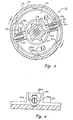
- the apparatus includes a head 11 which is normally supported on the lower end of a handle (not shown).
- Head 11 includes a housing 13.
- Housing 13 has cooling fins 14 on its upper surface and an annular depending wall 15.
- Two apertures 17 are formed in wall 15 and located 180 degrees apart from each other.
- a hub 19 is a generally cylindrical member having a passage through it for receiving a drive shaft member 21.
- the drive shaft member 21 has a lower rectangular portion 21b for transmitting rotational motion from an electrical motor or gasoline engine (not shown).
- a cylindrical portion 21a a is located at the centre of the drive shaft member 21.
- a plurality of stop members in the form of teeth 23 are formed on the hub 19. Teeth 23 are spaced in a circular array around the axis of rotation of the head 11, the teeth 23 being generally rectangular. Each tooth has a bevelled corner on the leading edge thereof.
- a plurality of cam members 25 are located on the inner side of the wall 15 of the housing 13. There are the same number of cam members 25 as there are teeth 23.
- Each cam member has a ramp portion 25a which is a gradually sloping portion that extends inwardly from the inner surface of wall 15. The ramp portion terminates in an inner portion 25b which curves at the same rate as the curvature of the inner surface of the wall 15.
- the side surface of each cam member 25 opposite the ramp portion 25a is located on a radial line, forming a sharp corner.
- the ramp portion 25a extends in the same direction as the direction of rotation, as indicated by the arrow.
- Rotor 27 is carried in the housing 13.
- Rotor 27 is basically a circular plate that is retained with the drive shaft 21 by means of a bolt 28.
- Bolt 28 bears against the lower end of the drive shaft member 21, with the center of the rotor 27 being located in the rectangular portion 21 b of the drive shaft member 21. Rotor 27 thus always rotates with drive shaft 21, while housing 13 will slip relative to drive shaft 21 as explained subsequently.
- Each mounting block 29 is a two-piece generally rectangular member (see Figure 4), having a lower portion 29a integral with rotor 27 and a cap 29b secured thereto. Each block 29 has a cavity 30 therein.
- a locking pin or locking link 31 is carried in each cavity along a radial line emanating from the axis of rotation of the head 11. Pin 31 has a rectangular head 31a that is adapted to be engaged by the leading surfaces of the teeth 23. The remaining portion is cylindrical, except for the outer end 31 b, which has two vertical flat bevels. The bevelled end 31 b is adapted to contact the cam members 25.
- each cam member 25 is staggered rotationally a few degrees from each tooth 23. This allows the pin 31 to move under increased centrifugal force from the inward position shown in Figure 2 to a disengaging position, as shown in Figure 3. In the disengaging position, the head portion 31a will not be in contact with any of the teeth 23.
- the length of the pin 31 is selected so that when in contact with the inner portion 25b of a cam member 25, its head 31 a will be pushed back between two of the teeth 23.
- a coiled spring 33 encircles the central portion of the pin 31, and presses against the head 31 a to push pin 31 inwardly.
- the stiffness of spring 33 and the weight of the pin 31 are selected so that centrifugal force will overcome the force of spring 33 and force the pin 31 into a disengaged position when the rotation speed has increased to a selected maximum.
- rotor 27 has three holes 35 located in its flat surface for receiving lugs 37 formed on top of a spool 39.
- the lugs 37 have enlarged heads that fit through an enlarged portion of each slot 35 and slide into a narrow or elongated portion of each slot 35 to releasably retain the spool 39 with the rotor 27.
- the spool 39 has an annular compartment for receiving a supply of flexible line 41, with two free end portions, each extending out an aperture 17. The free ends extend into a cutting plane that is perpendicular to the axis of rotation of the head 11.
- Spool 39 is rigidly locked to the rotor 27 for rotation therewith.
- Housing 13 is free to slip relative to rotor 27 and spool 39 when the locking pins 31 are out of engagement with the teeth 23.
- a bottom cover 43 is releasably secured to the bottom of the housing 13, enclosing the spool 39.
- Cover 43 has a smooth glide ball portion on the lower end. It has a lip 45 on the upper end that has four slots (not shown), each receiving a tab 47 projecting outward on the lower end of the housing 13. The cover 43 is twisted relative to housing 13 once the tabs 47 are in the slots, to releasably lock the cover 43 to the housing 13.
- the power source (not shown) rotates the drive shaft member 21, which in turn rotates the rotor 27 and spool 39.
- the forces acting on the lines 41 are transferred to the housing 13 at the regions of the apertures 17, and tend to advance the housing 13 clockwise, as viewed in Figures 1 and 2, with respect to the spool. This is the direction of relative movement which tends to unwind the line.
- the pins 31 are in their innermost positions and thus advance of the housing can only continue until two opposed teeth 23 encounter the pins 31.
- the housing is shown in its most advanced position with respect to the spool.
- Line is fed out automatically when it shortens, avoiding the need for the operator to detect when the line is too short.
- the cam members, with the ramp portions assures that only a predetermined increment of line will be fed out each time.
Landscapes
- Life Sciences & Earth Sciences (AREA)
- Environmental Sciences (AREA)
- Harvester Elements (AREA)
Claims (5)
Applications Claiming Priority (4)
| Application Number | Priority Date | Filing Date | Title |
|---|---|---|---|
| ZA845330 | 1984-07-11 | ||
| ZA845330 | 1984-07-11 | ||
| ZA85992 | 1985-02-08 | ||
| ZA850992 | 1985-02-08 |
Publications (3)
| Publication Number | Publication Date |
|---|---|
| EP0168254A2 EP0168254A2 (fr) | 1986-01-15 |
| EP0168254A3 EP0168254A3 (en) | 1986-07-30 |
| EP0168254B1 true EP0168254B1 (fr) | 1990-04-25 |
Family
ID=27135575
Family Applications (1)
| Application Number | Title | Priority Date | Filing Date |
|---|---|---|---|
| EP85304964A Expired - Lifetime EP0168254B1 (fr) | 1984-07-11 | 1985-07-11 | Tondeuse à cordon pour couper des plantes |
Country Status (6)
| Country | Link |
|---|---|
| US (1) | US4660286A (fr) |
| EP (1) | EP0168254B1 (fr) |
| AU (1) | AU581909B2 (fr) |
| CA (1) | CA1265934A (fr) |
| DE (1) | DE3577261D1 (fr) |
| NZ (1) | NZ212711A (fr) |
Families Citing this family (29)
| Publication number | Priority date | Publication date | Assignee | Title |
|---|---|---|---|---|
| US5276968A (en) * | 1978-03-30 | 1994-01-11 | White Consolidated Industries, Inc. | Apparatus for cutting vegetation |
| US4835867A (en) * | 1984-07-16 | 1989-06-06 | White Consolidated Industries, Inc. | Apparatus for cutting vegetation |
| AU593335B2 (en) * | 1986-03-25 | 1990-02-08 | Sugihara Rinki Kabushiki Kaisha | Cutting head for cord type mower |
| AU592679B2 (en) * | 1987-10-28 | 1990-01-18 | White Consolidated Industries, Inc. | Apparatus for cutting vegetation |
| CA1319018C (fr) * | 1987-11-04 | 1993-06-15 | Maria Rosa Calcinai | Appareil debroussaillage/tondeuse a organes de coupe allongeables et raccordements associes |
| US5020224A (en) * | 1988-07-21 | 1991-06-04 | White Consolidated Industries, Inc. | Semi-automatic string trimmer head |
| US4926557A (en) * | 1988-07-21 | 1990-05-22 | Allegretti & Company | Semi-automatic string trimmer head |
| US4987681A (en) * | 1988-10-31 | 1991-01-29 | White Consolidated Industries, Inc. | Hand held cordless grass/weed trimmer |
| US4888871A (en) * | 1989-01-11 | 1989-12-26 | Centiforce (Proprietary) Limited | Driving head for line cutting devices |
| US5109607A (en) * | 1990-10-12 | 1992-05-05 | Inertia Dynamics Corporation | Automatic line trimmer head |
| US5311665A (en) * | 1990-11-16 | 1994-05-17 | Diatop Corporation | Cutting head for a cord type mower |
| JP3113270B2 (ja) * | 1990-11-16 | 2000-11-27 | 杉原林機株式会社 | コード型草刈機の刈刃装置におけるコード繰出し機構 |
| US5060384A (en) * | 1990-12-06 | 1991-10-29 | Inertia Dynamics Corporation | Automatic head for a line trimmer |
| US5339526A (en) * | 1993-04-22 | 1994-08-23 | Ryobi Outdoor Products | Resistance spool for a line trimmer head |
| DE4411002A1 (de) * | 1994-03-30 | 1995-10-05 | Bosch Gmbh Robert | Gerät zum Schneiden von Pflanzen |
| US5675897A (en) * | 1996-05-01 | 1997-10-14 | Berfield; Robert C. | Rotary flail feeding device |
| US5743019A (en) * | 1995-06-07 | 1998-04-28 | Berfield; Robert C. | Rotary flail feeding device and method |
| US7111403B2 (en) | 1999-09-21 | 2006-09-26 | Moore Mark R | Head for line trimming apparatus |
| CN2459863Y (zh) * | 2000-12-04 | 2001-11-21 | 苏州太湖企业有限公司 | 割草机的自动放线机构 |
| DE10061030B4 (de) * | 2000-12-08 | 2004-12-02 | Dr. Franz Schneider Kunststoffwerke Gmbh & Co. Kg | Einrichtung mit einem sich um eine Achse drehenden Element |
| ITTO20060746A1 (it) * | 2006-10-17 | 2008-04-18 | Arol Spa | "dispositivo di attacco rapido" |
| US7536792B2 (en) * | 2007-01-03 | 2009-05-26 | Moore Mark R | Head for a rotary line trimmer apparatus |
| EP2798934B1 (fr) * | 2013-05-03 | 2018-02-21 | Black & Decker Inc. | Dispositif de coupe de végétation |
| AU2014337577A1 (en) | 2014-03-24 | 2015-10-08 | Husqvarna Ab | Quick loading trimmer head |
| DE202015009245U1 (de) | 2014-05-16 | 2017-02-23 | Positec Power Tools (Suzhou) Co., Ltd | Rasentrimmer |
| ES2772766T3 (es) * | 2014-10-21 | 2020-07-08 | Tecomec Srl | Un cuerpo de golpeteo para un cabezal para una recortadora de bordes y un cabezal para una recortadora de bordes |
| US20160183452A1 (en) | 2014-12-29 | 2016-06-30 | Husqvarna Ab | Quick loading trimmer head |
| US10034422B2 (en) | 2016-06-14 | 2018-07-31 | Black & Decker Inc. | Cutting head for a string trimmer |
| CN110181732B (zh) * | 2019-06-10 | 2021-01-01 | 安徽鸿海新材料股份有限公司 | 一种覆铜板生产制造修边系统及其操作方法 |
Family Cites Families (9)
| Publication number | Priority date | Publication date | Assignee | Title |
|---|---|---|---|---|
| US4104796A (en) * | 1977-07-29 | 1978-08-08 | Sheldon John D | Filament-type trimmer |
| DE2828425A1 (de) * | 1978-06-28 | 1980-01-10 | Stihl Maschf Andreas | Pflanzenschneidgeraet |
| US4287670A (en) * | 1978-07-28 | 1981-09-08 | Textron, Inc. | Filament-type trimmer |
| JPS5833849Y2 (ja) * | 1978-08-18 | 1983-07-29 | 株式会社共立 | 刈払機の滑動接地円板装置 |
| US4245454A (en) * | 1979-02-12 | 1981-01-20 | The Toro Company | Line metering apparatus |
| US4195408A (en) * | 1979-03-01 | 1980-04-01 | Palmieri John P | Convertible, automatic to manual, nylon line vegetation cutter |
| US4483069A (en) * | 1979-08-01 | 1984-11-20 | Emerson Electric Co. | Apparatus for cutting vegetation |
| US4347666A (en) * | 1980-07-25 | 1982-09-07 | Emerson Electric Co. | Apparatus for cutting vegetation |
| US4426780A (en) * | 1981-09-03 | 1984-01-24 | The Toro Company | Line metering apparatus |
-
1985
- 1985-07-10 US US06/753,649 patent/US4660286A/en not_active Expired - Fee Related
- 1985-07-11 NZ NZ212711A patent/NZ212711A/en unknown
- 1985-07-11 AU AU44811/85A patent/AU581909B2/en not_active Ceased
- 1985-07-11 DE DE8585304964T patent/DE3577261D1/de not_active Expired - Fee Related
- 1985-07-11 EP EP85304964A patent/EP0168254B1/fr not_active Expired - Lifetime
- 1985-07-11 CA CA000486647A patent/CA1265934A/fr not_active Expired - Fee Related
Also Published As
| Publication number | Publication date |
|---|---|
| EP0168254A3 (en) | 1986-07-30 |
| EP0168254A2 (fr) | 1986-01-15 |
| NZ212711A (en) | 1987-11-27 |
| AU581909B2 (en) | 1989-03-09 |
| CA1265934A (fr) | 1990-02-20 |
| AU4481185A (en) | 1986-01-16 |
| US4660286A (en) | 1987-04-28 |
| DE3577261D1 (de) | 1990-05-31 |
Similar Documents
| Publication | Publication Date | Title |
|---|---|---|
| EP0168254B1 (fr) | Tondeuse à cordon pour couper des plantes | |
| EP0140634B1 (fr) | Appareil de coupe à filament | |
| CA2541000C (fr) | Tete pour coupe-gazon rotatifs a fil souple | |
| EP0351989B2 (fr) | Tête semi-automatique pour faucheuse à filament | |
| US4584771A (en) | Line metering apparatus | |
| US4823465A (en) | Line feed mechanism for line trimmers | |
| US5109607A (en) | Automatic line trimmer head | |
| US5020224A (en) | Semi-automatic string trimmer head | |
| US4236309A (en) | Flexible line trimmer with line feeding apparatus | |
| US4168572A (en) | Apparatus for cutting vegetation | |
| US4274201A (en) | Rotary cutting assembly with filament feed | |
| US4524515A (en) | Rotary cutting assembly with filament feed | |
| US4790071A (en) | Line trimmer with replaceable cutting blade assembly | |
| US4412382A (en) | Line feed mechanism for filament cutting | |
| US4490910A (en) | Cutting head for string trimmer | |
| EP0467006B1 (fr) | Appareil pour l'alimentation radiale centrifuge des fils de la tête de coupe pour tondeuse à filament ou similaire | |
| US3970258A (en) | Mincing machine | |
| US5063673A (en) | Vegetation cutters | |
| GB2078075A (en) | A mowing machine | |
| US4245454A (en) | Line metering apparatus | |
| US4866846A (en) | Cutterhead for a vegetation cutter | |
| CA1298977C (fr) | Mecanisme d'alimentation pour tondeuse a fil | |
| US5383542A (en) | Overrunning clutch | |
| EP1004232B1 (fr) | Outil de coupe rotatif pour faucheuse | |
| EP1538360B1 (fr) | Embrayage centrifuge comprenant un dispositif de retenue chaussure |
Legal Events
| Date | Code | Title | Description |
|---|---|---|---|
| PUAI | Public reference made under article 153(3) epc to a published international application that has entered the european phase |
Free format text: ORIGINAL CODE: 0009012 |
|
| AK | Designated contracting states |
Designated state(s): DE FR GB IT NL |
|
| PUAL | Search report despatched |
Free format text: ORIGINAL CODE: 0009013 |
|
| RHK1 | Main classification (correction) |
Ipc: A01D 34/73 |
|
| AK | Designated contracting states |
Kind code of ref document: A3 Designated state(s): DE FR GB IT NL |
|
| 17P | Request for examination filed |
Effective date: 19870130 |
|
| 17Q | First examination report despatched |
Effective date: 19880915 |
|
| GRAA | (expected) grant |
Free format text: ORIGINAL CODE: 0009210 |
|
| AK | Designated contracting states |
Kind code of ref document: B1 Designated state(s): DE FR GB IT NL |
|
| PG25 | Lapsed in a contracting state [announced via postgrant information from national office to epo] |
Ref country code: NL Effective date: 19900425 Ref country code: IT Free format text: LAPSE BECAUSE OF FAILURE TO SUBMIT A TRANSLATION OF THE DESCRIPTION OR TO PAY THE FEE WITHIN THE PRESCRIBED TIME-LIMIT;WARNING: LAPSES OF ITALIAN PATENTS WITH EFFECTIVE DATE BEFORE 2007 MAY HAVE OCCURRED AT ANY TIME BEFORE 2007. THE CORRECT EFFECTIVE DATE MAY BE DIFFERENT FROM THE ONE RECORDED. Effective date: 19900425 |
|
| REF | Corresponds to: |
Ref document number: 3577261 Country of ref document: DE Date of ref document: 19900531 |
|
| ET | Fr: translation filed | ||
| NLV1 | Nl: lapsed or annulled due to failure to fulfill the requirements of art. 29p and 29m of the patents act | ||
| PLBE | No opposition filed within time limit |
Free format text: ORIGINAL CODE: 0009261 |
|
| STAA | Information on the status of an ep patent application or granted ep patent |
Free format text: STATUS: NO OPPOSITION FILED WITHIN TIME LIMIT |
|
| 26N | No opposition filed | ||
| PGFP | Annual fee paid to national office [announced via postgrant information from national office to epo] |
Ref country code: GB Payment date: 19910614 Year of fee payment: 7 |
|
| PGFP | Annual fee paid to national office [announced via postgrant information from national office to epo] |
Ref country code: FR Payment date: 19910621 Year of fee payment: 7 |
|
| PGFP | Annual fee paid to national office [announced via postgrant information from national office to epo] |
Ref country code: DE Payment date: 19910909 Year of fee payment: 7 |
|
| PG25 | Lapsed in a contracting state [announced via postgrant information from national office to epo] |
Ref country code: GB Effective date: 19920711 |
|
| GBPC | Gb: european patent ceased through non-payment of renewal fee |
Effective date: 19920711 |
|
| PG25 | Lapsed in a contracting state [announced via postgrant information from national office to epo] |
Ref country code: FR Effective date: 19930331 |
|
| PG25 | Lapsed in a contracting state [announced via postgrant information from national office to epo] |
Ref country code: DE Effective date: 19930401 |
|
| REG | Reference to a national code |
Ref country code: FR Ref legal event code: ST |