EP0168141A2 - Gerät und Verfahren zum Zusammenfassen von mit Kontakten versehenen Drähten zur Herstellung von Kabelbäumen - Google Patents
Gerät und Verfahren zum Zusammenfassen von mit Kontakten versehenen Drähten zur Herstellung von Kabelbäumen Download PDFInfo
- Publication number
- EP0168141A2 EP0168141A2 EP85303462A EP85303462A EP0168141A2 EP 0168141 A2 EP0168141 A2 EP 0168141A2 EP 85303462 A EP85303462 A EP 85303462A EP 85303462 A EP85303462 A EP 85303462A EP 0168141 A2 EP0168141 A2 EP 0168141A2
- Authority
- EP
- European Patent Office
- Prior art keywords
- wire
- connector
- terminals
- terminal
- row
- Prior art date
- Legal status (The legal status is an assumption and is not a legal conclusion. Google has not performed a legal analysis and makes no representation as to the accuracy of the status listed.)
- Granted
Links
Images


Classifications
-
- H—ELECTRICITY
- H01—ELECTRIC ELEMENTS
- H01R—ELECTRICALLY-CONDUCTIVE CONNECTIONS; STRUCTURAL ASSOCIATIONS OF A PLURALITY OF MUTUALLY-INSULATED ELECTRICAL CONNECTING ELEMENTS; COUPLING DEVICES; CURRENT COLLECTORS
- H01R43/00—Apparatus or processes specially adapted for manufacturing, assembling, maintaining, or repairing of line connectors or current collectors or for joining electric conductors
- H01R43/01—Apparatus or processes specially adapted for manufacturing, assembling, maintaining, or repairing of line connectors or current collectors or for joining electric conductors for connecting unstripped conductors to contact members having insulation cutting edges
-
- H—ELECTRICITY
- H01—ELECTRIC ELEMENTS
- H01R—ELECTRICALLY-CONDUCTIVE CONNECTIONS; STRUCTURAL ASSOCIATIONS OF A PLURALITY OF MUTUALLY-INSULATED ELECTRICAL CONNECTING ELEMENTS; COUPLING DEVICES; CURRENT COLLECTORS
- H01R43/00—Apparatus or processes specially adapted for manufacturing, assembling, maintaining, or repairing of line connectors or current collectors or for joining electric conductors
- H01R43/28—Apparatus or processes specially adapted for manufacturing, assembling, maintaining, or repairing of line connectors or current collectors or for joining electric conductors for wire processing before connecting to contact members, not provided for in groups H01R43/02 - H01R43/26
Definitions
- the present invention relates to apparatus and method for assembling terminated wires into electrical connectors to form harnesses and concerns apparatus and method for the manufacture of electrical cable harnesses of the type including a connector electrically connected to a plurality of discrete wire conductors, the connector having a housing with a plurality of terminals mounted therein, the terminals having insulation displacing slot means for termination with said wire conductors.
- Such apparatus has been manually fed with discrete wire conductors by an operator positioning the free ends of the conductors in the "Y" direction one at a time at the termination station for alignment by the aligning means, the operator then operating the terminator to terminate the conductor in the connector in the "Z" direction.
- the object of the present invention is to provide apparatus and method for assembling discrete wire conductors into a connector, one at a time, and at different levels in the connector to form a cable harness of the type described.
- the apparatus of the present invention is characterised in that said terminals of said connector are arranged in two rows extending in said "X" direction and spaced apart from each other in said "Y” and said "Z” directions, with the terminals of one row being offset from the terminals of the other row in said "X " direction; said indexing means including an indexable nest movable in said "X” and said "Y” directions, for receiving at least one of said connectors; means for selectively moving said indexable nest in said "X” and said "Y” directions to present a predetermined sequence of terminals one at a time to said termination station; and said insertion blade having at least two insertion strokes of different lengths, one stroke for each row of terminals, for inserting the free end of a wire conductor in said insulation displacing slot means of each terminal located in each of said rows.
- the method of the present invention comprises the steps of presenting said connector at a termination station, indexing the connector in an "X" direction to present a terminal of one-row of the connector at said termination station, aligning the free end of a wire conductor at a predetermined point over said terminal, and inserting the wire free end in said insulation displacing slot means of said terminal, and is characterised by the further steps of providing a connector with a second row of preloaded terminals, said first and second rows each extending in an "X" direction and spaced'apart from each other in "Y” and “Z” mutually-perpendicular directions with the terminals of one row being offset from the terminals of the other row in said "X” direction, indexing the connector in both said "X” and said "Y” directions to present another terminal taken from the second row at the termination station; and inserting another wire free end in said insulation displacing slot means of said other terminal.
- the machine comprises a horizontal wire feed unit 9 including a wire straightener 10 for wire 11 fed from a reel (not shown), a wire length encoder wheel 12 and a wire presser wheel 14 and wire feed drive rolls 16.
- the wire feed unit 9 further includes an encoder and stepping motor and control and wire processing printed circuit boards, the latter permitting two functions:
- the machine further comprises a fixture unit 20 including a nest or fixture plate 21 to accomodate a horizontal feed at right angles to the wire feed, e.g. of a linked chain 23 (see Fig. 2) of insulation displacement terminal (IDT) connectors 24 formed as plug sockets and constructed as described in our Patent Application No. 84 30 6787.7.
- a fixture unit 20 including a nest or fixture plate 21 to accomodate a horizontal feed at right angles to the wire feed, e.g. of a linked chain 23 (see Fig. 2) of insulation displacement terminal (IDT) connectors 24 formed as plug sockets and constructed as described in our Patent Application No. 84 30 6787.7.
- IDT insulation displacement terminal
- Loose piece connectors such as 24 may alternatively be hand fed into the nest 21.
- the fixture unit 20 further comprises an "X" movement table 25 mounted on a “Y” movement table 26.
- the nest 21 is mounted on the "X” movement table which is displaceable on an "X” axis in the direction of the connector feed.
- the "Y” movement table is displaceable on a “Y” axis at right angles to the direction of connector feed.
- Two cams 50 and 51 operate the “X” and “Y” tables respectively, the cams being mounted on a common shaft and operated by a stepping motor 53 (e.g. 8 x 45° intervals) under the control of the control printed cirecuit board incorporated in the unit 9.
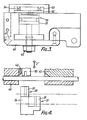
- Connectors 24 are advanced in turn along the nest 21 to a "start" position or termination station in which the first of an upper tier 30 (see Fig. 4) of terminal wire receiving slots 31 is at an insertion station vertically below a vertically displaceable, "Z" movement wire insertion blade 33.
- the insertion blade is arranged to be driven downwardly by a pneumatically operable insertion cylinder 35 with a movable stop for two heights (or depths) of insertion of the blade, one of which is illustrated in Fig. 5 (blade inserted in upper tier 30) of connector and the other of which is illustrated in Fig. 6 (blade inserted in lower tier 37) of connector.
- the terminal wire receiving slots 31 are all uniquely positioned along the tiers 30,37 in the "X" direction and adjacent slots 31 are positioned in the two tiers 30, 37 respectively.
- the "X" table is stepped one slot by its cam 50 and the "Y” table is shifted by its cam 51 to align the next adjacent slot 31 in the lower tier 37 in the insertion station, and so on, the "X” table being shifted stepwise in a forward direction only, to carry terminated wires clear of the insertion station, and the "Y” table being shifted to and fro successively to align the upper and lower tiers of terminal wire receiving slots in the insertion station.
- a wire feed guide 40 is incorporated on the wire feed side of a wire cutter blade42 operated by the insertion cylinder each time the insertion blade 33 is driven downwardly.
- the machine further comprises a wire gripper 45, details of which are shown in Fig. 3.
- the unit 45 is carried with the insertion blade 33 from the insertion cylinder 35 and has a closed (wire gripping) position, a semi-open (wire guiding) position and a fully open (wire disengaging) position.
- the wire gripper 45 comprises an upper jaw member 47 which is fixed relative to the insertion blade 33, a lower pivoted jaw member 48 which swings away from the fixed jaw member, first to the semi-open and then to the fully open position, and a duplex pneumatic piston and cylinder arrangement generally indicated at 50 for activating the clamp between its closed, semi-open and fully open positions.
- Air under pressure is supplied to opposite sides of the main piston 51 to close and fully open the clamp respectively.
- air under pressure supplied to the underside of piston 51 holds a secondary piston 52 displaced in a cylinder 53 against springs 54 acting on the upper side of the piston 52.
- Reduction of the pneumatic closing force below the force of the springs 54 opens the clamp a predetermined amount controlled by the downward movement permitted to the piston 52.
- the piston 52 is held in engagement with the piston 51 by the springs 54.
- Air under pressure to fully open the clamp is supplied to the cylinder 53 and is communicated with the upper side of the piston 51 through a fluid port in the piston 52.
- a connector 24 is fed to position the first terminal wire receiving slot 31 at the insertion station.
- the wire gripper 45 is moved to its semi-open position. Wire feed is provided by the unit 9 for the first wire either in one single length A or in lengths Al and A2 for termination of the leading end of the wire in an individual, rotatable or retractable termination unit (not shown) rotatable or retractable to enable the wire feed A2 to take place.
- the wire gripper 45 is then closed.
- the wire cutter blade 42 is then actuated and the wire is transferred and inserted by the insertion blade whilst being held-by the wire gripper 45.
- the wire gripper 45 is then moved to its fully open position and the connector 24 is displaced by movement of the "XY" tables to align the second terminal wire receiving slot at the insertion station and the machine resets to repeat the cycle of operations described, the wire gripper 45 moving to its semi-open, i.e. feed position, to receive and guide the next wire length.
- the chain 23 of connectors is fed forward to align a fresh connector at the insertion station.
- a finished harness is chopped from the harness chain.
- the "XY" movement tables, coupled with the dual height insertion unit, can be used on a "Megomat" ASM 1000 in the same manner as a standard press, substituting the ASM 1000 special right hand wire gripper for the wire gripper 45 described.
- the "XY" movement tables 24, 25 coupled with the dual height insertion unit 35 and wire gripper 45 may be used with the wire feed and measure unit 9 (Megomat) described to produce single harnesses and jack harnesses automatically or semi-automatically.
- split wire feed feature permits the use of a supplementary stripper/crimper unit for individually terminating the individual opposite ends of harness wires or the use of an IDT press for double ended IDT.
- All the harnesses will use wire lengths cut from one single wire. To identify the different wire lengths a wire marking unit may be incorporated.
- discrete wire conductors may be manually fed by an operator in the "Y" direction, one at a time, to the termination station for termination in successive slots 31 in the upper and lower tiers of each connector if desired, the successive slots 31 being aligned at the termination station and the wires terminated in the connector by operating the machine.
Applications Claiming Priority (2)
| Application Number | Priority Date | Filing Date | Title |
|---|---|---|---|
| GB848412827A GB8412827D0 (en) | 1984-05-18 | 1984-05-18 | Terminated wires into electrical connectors |
| GB8412827 | 1984-05-18 |
Publications (3)
| Publication Number | Publication Date |
|---|---|
| EP0168141A2 true EP0168141A2 (de) | 1986-01-15 |
| EP0168141A3 EP0168141A3 (en) | 1987-05-13 |
| EP0168141B1 EP0168141B1 (de) | 1989-10-25 |
Family
ID=10561197
Family Applications (1)
| Application Number | Title | Priority Date | Filing Date |
|---|---|---|---|
| EP19850303462 Expired EP0168141B1 (de) | 1984-05-18 | 1985-05-17 | Gerät und Verfahren zum Zusammenfassen von mit Kontakten versehenen Drähten zur Herstellung von Kabelbäumen |
Country Status (3)
| Country | Link |
|---|---|
| EP (1) | EP0168141B1 (de) |
| DE (1) | DE3573966D1 (de) |
| GB (1) | GB8412827D0 (de) |
Cited By (7)
| Publication number | Priority date | Publication date | Assignee | Title |
|---|---|---|---|---|
| EP0241939A1 (de) * | 1986-04-18 | 1987-10-21 | Sumitomo Wiring Systems, Ltd. | Verfahren und Vorrichtung zur Herstellung von Kabelbäumen |
| DE3821432A1 (de) * | 1987-06-25 | 1989-01-05 | Amp Inc | Vorrichtung zur verwendung beim anschliessen elektrischer draehte an anschluesse eines elektrischen verbinders |
| EP0635915A2 (de) * | 1988-09-07 | 1995-01-25 | Molex Incorporated | Verbinderanschlussvorrichtung und Methode |
| EP0833417A2 (de) * | 1996-09-27 | 1998-04-01 | Harness System Technologies Research, Ltd. | Verfahren zur Herstellung eines Kabelbaumes |
| EP0844703A1 (de) * | 1996-11-22 | 1998-05-27 | Molex Incorporated | Kabelanschlussgerät zur Herstellung von Kabelbäumen |
| EP0862251A1 (de) * | 1997-02-26 | 1998-09-02 | Harness System Technologies Research, Ltd. | Verfahren zur Herstellung eines Kabelbaumes für den Automobilbau |
| US11239622B2 (en) * | 2018-02-01 | 2022-02-01 | Aptiv Technologies Limited | System for connecting wires of an electrical cable harness to an electrical connector |
Citations (2)
| Publication number | Priority date | Publication date | Assignee | Title |
|---|---|---|---|---|
| US4043017A (en) * | 1976-02-11 | 1977-08-23 | Amp Incorporated | Apparatus for inserting wires into terminals and for manufacturing electrical harnesses |
| EP0063908A1 (de) * | 1981-04-27 | 1982-11-03 | AMP INCORPORATED (a New Jersey corporation) | Anordnung zum Identifizieren und Abschliessen eines Drahtes |
-
1984
- 1984-05-18 GB GB848412827A patent/GB8412827D0/en active Pending
-
1985
- 1985-05-17 EP EP19850303462 patent/EP0168141B1/de not_active Expired
- 1985-05-17 DE DE8585303462T patent/DE3573966D1/de not_active Expired
Patent Citations (2)
| Publication number | Priority date | Publication date | Assignee | Title |
|---|---|---|---|---|
| US4043017A (en) * | 1976-02-11 | 1977-08-23 | Amp Incorporated | Apparatus for inserting wires into terminals and for manufacturing electrical harnesses |
| EP0063908A1 (de) * | 1981-04-27 | 1982-11-03 | AMP INCORPORATED (a New Jersey corporation) | Anordnung zum Identifizieren und Abschliessen eines Drahtes |
Cited By (13)
| Publication number | Priority date | Publication date | Assignee | Title |
|---|---|---|---|---|
| EP0241939A1 (de) * | 1986-04-18 | 1987-10-21 | Sumitomo Wiring Systems, Ltd. | Verfahren und Vorrichtung zur Herstellung von Kabelbäumen |
| DE3821432A1 (de) * | 1987-06-25 | 1989-01-05 | Amp Inc | Vorrichtung zur verwendung beim anschliessen elektrischer draehte an anschluesse eines elektrischen verbinders |
| DE3821432B4 (de) * | 1987-06-25 | 2004-09-02 | Amp Inc. | Vorrichtung zur Verwendung bei einem elektrischen Verbinder |
| EP0635915A2 (de) * | 1988-09-07 | 1995-01-25 | Molex Incorporated | Verbinderanschlussvorrichtung und Methode |
| EP0635915A3 (en) * | 1988-09-07 | 1995-02-22 | Molex Inc | Connector termination apparatus and method. |
| US6170152B1 (en) | 1996-09-27 | 2001-01-09 | Harness System Technologies Research, Ltd. | Apparatus for making a wire harness |
| EP0833417A3 (de) * | 1996-09-27 | 1999-11-10 | Harness System Technologies Research, Ltd. | Verfahren zur Herstellung eines Kabelbaumes |
| EP0833417A2 (de) * | 1996-09-27 | 1998-04-01 | Harness System Technologies Research, Ltd. | Verfahren zur Herstellung eines Kabelbaumes |
| EP0844703A1 (de) * | 1996-11-22 | 1998-05-27 | Molex Incorporated | Kabelanschlussgerät zur Herstellung von Kabelbäumen |
| EP0862251A1 (de) * | 1997-02-26 | 1998-09-02 | Harness System Technologies Research, Ltd. | Verfahren zur Herstellung eines Kabelbaumes für den Automobilbau |
| US5970609A (en) * | 1997-02-26 | 1999-10-26 | Harness System Technologies Research, Ltd. | Method of manufacturing wire harness for automobile use |
| CN1080012C (zh) * | 1997-02-26 | 2002-02-27 | 株式会社自动车电网络技术研究所 | 线束的制造方法 |
| US11239622B2 (en) * | 2018-02-01 | 2022-02-01 | Aptiv Technologies Limited | System for connecting wires of an electrical cable harness to an electrical connector |
Also Published As
| Publication number | Publication date |
|---|---|
| EP0168141B1 (de) | 1989-10-25 |
| DE3573966D1 (en) | 1989-11-30 |
| EP0168141A3 (en) | 1987-05-13 |
| GB8412827D0 (en) | 1984-06-27 |
Similar Documents
| Publication | Publication Date | Title |
|---|---|---|
| EP0000428B1 (de) | Verfahren und Vorrichtung zur Herstellung von elektrischen Kabelbäumen | |
| EP0132092B1 (de) | Vorrichtung zur Herstellung eines Kabelbaumes | |
| US4126935A (en) | Method and apparatus for manufacturing wiring harnesses | |
| EP0182528B1 (de) | Gerät zur Anordnung von mit Endkontakten versehenen Drähten zur Schaffung von Kabelbäumen | |
| EP0008155B1 (de) | Verfahren und Apparat zum Herstellen von Drahtbündeln | |
| US4148130A (en) | Cable harness assembly apparatus | |
| EP0810698A2 (de) | Kabelbaum für Kraftfahrzeug und Verfahren und Vorrichtung zu dessen Herstellung | |
| US9787046B2 (en) | Wire sorting fixture and method of sorting wires | |
| US4125137A (en) | Apparatus for locating wires in predetermined co-planar relationship to each other | |
| EP0040490B1 (de) | Gerät und Verfahren zum Kontaktieren eines Mehrleiter-Flachkabels mit Endkontakten | |
| EP0206464B1 (de) | Vorrichtung zur Herstellung von elektrischen Kabelbäumen | |
| EP0168141B1 (de) | Gerät und Verfahren zum Zusammenfassen von mit Kontakten versehenen Drähten zur Herstellung von Kabelbäumen | |
| US4516309A (en) | Apparatus for assembling an electrical connector to a cable | |
| KR910004800B1 (ko) | 하아네스 제조 장치 및 방법 | |
| CA1167626A (en) | Apparatus for, and a method of, serially manufacturing electrical harness assemblies | |
| EP0817329B1 (de) | Vorrichtung zur Herstellung von Kabelbäumen | |
| EP0145416B1 (de) | Apparat zur Herstellung von elektrischen Drahtbäumen | |
| US3848316A (en) | Lead wire assembly apparatus | |
| US5020216A (en) | Apparatus for loading cable on connector | |
| EP0001678B1 (de) | Gerät zum Entfalten und Ausrichten von Drähten | |
| US5745991A (en) | Machine and method for producing electrical harness | |
| US4651413A (en) | Wire jig intended for use in a harness-making machine or the like | |
| US4881321A (en) | Method and apparatus for making a harness | |
| EP0177359A2 (de) | Vorrichtung zur Herstellung von elektrischen Kabelbäumen | |
| EP0167985A2 (de) | Automatische Verdrahtungsstation hauptsächlich für Maschinen zur Längenschneidenzubereitung elektrischer Drähte, versehen mit isolierbaren, elektrischen Anschlüssen |
Legal Events
| Date | Code | Title | Description |
|---|---|---|---|
| PUAI | Public reference made under article 153(3) epc to a published international application that has entered the european phase |
Free format text: ORIGINAL CODE: 0009012 |
|
| AK | Designated contracting states |
Designated state(s): CH DE FR GB IT LI NL |
|
| PUAL | Search report despatched |
Free format text: ORIGINAL CODE: 0009013 |
|
| AK | Designated contracting states |
Kind code of ref document: A3 Designated state(s): CH DE FR GB IT LI NL |
|
| 17P | Request for examination filed |
Effective date: 19870527 |
|
| 17Q | First examination report despatched |
Effective date: 19880816 |
|
| GRAA | (expected) grant |
Free format text: ORIGINAL CODE: 0009210 |
|
| AK | Designated contracting states |
Kind code of ref document: B1 Designated state(s): CH DE FR GB IT LI NL |
|
| ITF | It: translation for a ep patent filed |
Owner name: BARZANO' E ZANARDO MILANO S.P.A. |
|
| REF | Corresponds to: |
Ref document number: 3573966 Country of ref document: DE Date of ref document: 19891130 |
|
| ET | Fr: translation filed | ||
| PLBE | No opposition filed within time limit |
Free format text: ORIGINAL CODE: 0009261 |
|
| STAA | Information on the status of an ep patent application or granted ep patent |
Free format text: STATUS: NO OPPOSITION FILED WITHIN TIME LIMIT |
|
| 26N | No opposition filed | ||
| ITTA | It: last paid annual fee | ||
| PGFP | Annual fee paid to national office [announced via postgrant information from national office to epo] |
Ref country code: GB Payment date: 19940412 Year of fee payment: 10 |
|
| PGFP | Annual fee paid to national office [announced via postgrant information from national office to epo] |
Ref country code: FR Payment date: 19940513 Year of fee payment: 10 |
|
| PGFP | Annual fee paid to national office [announced via postgrant information from national office to epo] |
Ref country code: DE Payment date: 19940527 Year of fee payment: 10 |
|
| PGFP | Annual fee paid to national office [announced via postgrant information from national office to epo] |
Ref country code: NL Payment date: 19940531 Year of fee payment: 10 |
|
| PGFP | Annual fee paid to national office [announced via postgrant information from national office to epo] |
Ref country code: CH Payment date: 19940718 Year of fee payment: 10 |
|
| PG25 | Lapsed in a contracting state [announced via postgrant information from national office to epo] |
Ref country code: GB Effective date: 19950517 |
|
| PG25 | Lapsed in a contracting state [announced via postgrant information from national office to epo] |
Ref country code: LI Effective date: 19950531 Ref country code: CH Effective date: 19950531 |
|
| PG25 | Lapsed in a contracting state [announced via postgrant information from national office to epo] |
Ref country code: NL Effective date: 19951201 |
|
| GBPC | Gb: european patent ceased through non-payment of renewal fee |
Effective date: 19950517 |
|
| REG | Reference to a national code |
Ref country code: CH Ref legal event code: PL |
|
| NLV4 | Nl: lapsed or anulled due to non-payment of the annual fee |
Effective date: 19951201 |
|
| PG25 | Lapsed in a contracting state [announced via postgrant information from national office to epo] |
Ref country code: DE Effective date: 19960201 |
|
| PG25 | Lapsed in a contracting state [announced via postgrant information from national office to epo] |
Ref country code: FR Effective date: 19960229 |
|
| REG | Reference to a national code |
Ref country code: FR Ref legal event code: ST |
|
| REG | Reference to a national code |
Ref country code: FR Ref legal event code: ST |