EP0168097A1 - Method and device for applying glass sheets on a frontage - Google Patents
Method and device for applying glass sheets on a frontage Download PDFInfo
- Publication number
- EP0168097A1 EP0168097A1 EP85201014A EP85201014A EP0168097A1 EP 0168097 A1 EP0168097 A1 EP 0168097A1 EP 85201014 A EP85201014 A EP 85201014A EP 85201014 A EP85201014 A EP 85201014A EP 0168097 A1 EP0168097 A1 EP 0168097A1
- Authority
- EP
- European Patent Office
- Prior art keywords
- profiles
- frontage
- glass sheet
- locking
- frontage part
- Prior art date
- Legal status (The legal status is an assumption and is not a legal conclusion. Google has not performed a legal analysis and makes no representation as to the accuracy of the status listed.)
- Granted
Links
- 239000011521 glass Substances 0.000 title claims abstract description 59
- 238000000034 method Methods 0.000 title claims abstract description 10
- 239000011248 coating agent Substances 0.000 claims description 7
- 238000000576 coating method Methods 0.000 claims description 7
- 239000003292 glue Substances 0.000 claims description 6
- 239000002184 metal Substances 0.000 claims description 5
- 238000007789 sealing Methods 0.000 description 2
- 230000000694 effects Effects 0.000 description 1
- 238000009418 renovation Methods 0.000 description 1
- 239000000126 substance Substances 0.000 description 1
Images

Classifications
-
- E—FIXED CONSTRUCTIONS
- E06—DOORS, WINDOWS, SHUTTERS, OR ROLLER BLINDS IN GENERAL; LADDERS
- E06B—FIXED OR MOVABLE CLOSURES FOR OPENINGS IN BUILDINGS, VEHICLES, FENCES OR LIKE ENCLOSURES IN GENERAL, e.g. DOORS, WINDOWS, BLINDS, GATES
- E06B3/00—Window sashes, door leaves, or like elements for closing wall or like openings; Layout of fixed or moving closures, e.g. windows in wall or like openings; Features of rigidly-mounted outer frames relating to the mounting of wing frames
- E06B3/54—Fixing of glass panes or like plates
- E06B3/5427—Fixing of glass panes or like plates the panes mounted flush with the surrounding frame or with the surrounding panes
-
- E—FIXED CONSTRUCTIONS
- E04—BUILDING
- E04F—FINISHING WORK ON BUILDINGS, e.g. STAIRS, FLOORS
- E04F13/00—Coverings or linings, e.g. for walls or ceilings
- E04F13/07—Coverings or linings, e.g. for walls or ceilings composed of covering or lining elements; Sub-structures therefor; Fastening means therefor
- E04F13/08—Coverings or linings, e.g. for walls or ceilings composed of covering or lining elements; Sub-structures therefor; Fastening means therefor composed of a plurality of similar covering or lining elements
- E04F13/0801—Separate fastening elements
- E04F13/0803—Separate fastening elements with load-supporting elongated furring elements between wall and covering elements
- E04F13/081—Separate fastening elements with load-supporting elongated furring elements between wall and covering elements with additional fastening elements between furring elements and covering elements
- E04F13/0821—Separate fastening elements with load-supporting elongated furring elements between wall and covering elements with additional fastening elements between furring elements and covering elements the additional fastening elements located in-between two adjacent covering elements
- E04F13/0826—Separate fastening elements with load-supporting elongated furring elements between wall and covering elements with additional fastening elements between furring elements and covering elements the additional fastening elements located in-between two adjacent covering elements engaging side grooves running along the whole length of the covering elements
Definitions
- the invention relates to a method of coating a frontage part with glass sheets, in which each time a glass sheet provided with supporting means is secured to the frontage part by means of fastening means engaging the supporting means.
- the object of the invention is to provide a simple method for aesthetically covering a frontage part, in which simple means need be arranged on glass sheets and a frontage part.
- the method embodying the invention is characterized in that the supporting means comprise two profiles each provided with two flanges parallel to the glass sheet, one flange being fastened by means of a glue layer previously applied to the glass sheet, whilst each time a glass sheet with the profiles arranged at the lower end of the glass plate is disposed at previously arranged hooks on the frontage part behind upwardly directed hook heads thereof and subsequently displaceable locking means previously arranged on the frontage part are moved into their locking position in which they engage the other flanges of the profiles of the glass sheet in a locking manner.
- the invention furthermore provides a device for applying a glass sheet on a frontage part comprising supporting means fastened to the glass sheets and fastening means engaging the supporting means characterized in that the supporting means comprise two profiles each having adjacent parallel flanges, one flange being fastened by means of a glue layer previously applied to the glass sheet, the fastening means comprise hooks secured to the frontage part, the hook heads being upwardly directed and engaging behind the hook heads and in that the fastening means comprise displaceable locking means arranged on the frontage part and being displaceable into a locking position, in which the locking means engage the other profile in a locking manner.
- the device claimed in claim 3 is used, since the hook heads inclined upwardly from the frontage part guide the glass sheets from top to bottom into the position in which they coat the frontage part.
- Frontage parts 1 are coated with glass sheets 2, for example, as outer walls of a building 19 (figure 1).
- the device 30 embodying the invention (figure 2) on the frontage parts 1 metal hollow profiles 7 are fastened by means of screws 9.
- fastening means 21 and locking means 22 are provided before the hollow profiles 7 are arranged on the frontage part 1.
- the fastening means 21 comprise hooks 43 having hook heads 4 inclined upwardly from the frontage part 1.
- a hook 3 is fixed to the profile 7 by means of screws 24 passing through a plate 28.
- Supporting means 20 are arranged previously preferably by means of a glue layer 13 on the glass sheets 2.
- the supporting means 20 comprise vertical, U-shaped profiles 5 of metal extending along substantially the whole length of the glass sheet 2, whilst their flange substantially parallel to the glass sheet engages at the lower end of the glass sheet 2 on the hooks 3 behind hook heads 4 in lowering the glass sheet 2 in the direction of the arrow Z. Subsequently the glass sheet 2 can be tilted in the direction of the arrow K until this glass sheet 2 is approximately in its vertical position.
- the locking means 22 also previously arranged on the profiles 7 preferably comprise (figure 3) lock bolts 6 rotatable in the direction of the arrow D when the U-profiles 5 fastened to the glass sheets in their vertical position are approximately near the hollow profiles 7.
- the lock bolts 6 are held in their locking position by stops 10.
- the lock bolts 6 are arranged pairwise on a carrier 8 so that each of them can lock a glass sheet.
- the carrier 8 is fastened by screws 25 to the profile 7.
- the lock bolts 6 are furthermore held by means of screws 11 in the profiles 7 co-operating with spring rings 12 arranged between the lock bolts 6 and the profiles 7.
- the variant shown in figure 4 comprises other supporting means 20 for the glass sheet 2, which comprise I-shaped metal profiles 105 engaging the hooks 3 and a supporting rim 14 fastened by means of a glue layer 114 to the underside of the glass sheet 2 and to the I-profiles 115.
- sliding lock bolts 15 fasten the profiles 5 to glass sheets in a locking manner on the profiles 7 fastened by screws 9 on the frontage part 1.
- the lock bolts 15 are furthermore arranged pairwise by means of screws 26 on a carrier 108.
- Receding frontage parts 71 having, for example, a sliding window 16 can also be coated in a simple manner with glass sheets 2 by means of the profiles 5, 7 (figure 10).
- the device 34 embodying the invention can also be used for coating a frontage part 1 with double glass sheets 72.
- the profiles 75 required for supporting the double glass sheets 72 may have the shape of a G. These profiles 75 are secured to the profiles by means of the fastening means 21 described above and the locking means 22.
- a board 29 behind the intermediate space 18 between two glass sheets 2, 72 is each time provided with a strip of silicon-like substance 27 by means of a spout 17 for sealing the coating of the frontage part 1.
Landscapes
- Engineering & Computer Science (AREA)
- Civil Engineering (AREA)
- Structural Engineering (AREA)
- Architecture (AREA)
- Securing Of Glass Panes Or The Like (AREA)
- Automobile Manufacture Line, Endless Track Vehicle, Trailer (AREA)
- Joining Of Glass To Other Materials (AREA)
- Aiming, Guidance, Guns With A Light Source, Armor, Camouflage, And Targets (AREA)
- Load-Bearing And Curtain Walls (AREA)
- Finishing Walls (AREA)
Abstract
Description
- The invention relates to a method of coating a frontage part with glass sheets, in which each time a glass sheet provided with supporting means is secured to the frontage part by means of fastening means engaging the supporting means.
- Such a method is known from French patent specification 2.016.357 in which a glass sheet unit is provided with a supporting frame and in which a complicated device is described for turning the glass sheet unit to a frontage about a hinge. The disadvantage of this device is that a supporting frame is required so that there will not be formed an uninterrupted glass wall and that a hinge with the associated complex supporting and fastening means is necessary for establishing a vertical position of the glass sheet unit.
- The object of the invention is to provide a simple method for aesthetically covering a frontage part, in which simple means need be arranged on glass sheets and a frontage part.
- To this end the method embodying the invention is characterized in that the supporting means comprise two profiles each provided with two flanges parallel to the glass sheet, one flange being fastened by means of a glue layer previously applied to the glass sheet, whilst each time a glass sheet with the profiles arranged at the lower end of the glass plate is disposed at previously arranged hooks on the frontage part behind upwardly directed hook heads thereof and subsequently displaceable locking means previously arranged on the frontage part are moved into their locking position in which they engage the other flanges of the profiles of the glass sheet in a locking manner.
- It is noted that in itself the disposition of panels on hook-shaped members is known from U.S. patent specification 2.251.991, in which, however, the panels are not metal enamelled panels and are provided with slots in which displaceable locking means are engaged. Since it is practically not possible to provide glass sheets with slots, this method cannot be used for coating a frontage part with glass sheets. Locking means are also known from U.S. patent specification 4.370.838. The purpose therein is the renovation of existing inner walls.of a building and thus not to apply glass sheets. Moreover, in this case there is not the problem of a high frontage, since the panels can be simply placed in rails.
- The invention furthermore provides a device for applying a glass sheet on a frontage part comprising supporting means fastened to the glass sheets and fastening means engaging the supporting means characterized in that the supporting means comprise two profiles each having adjacent parallel flanges, one flange being fastened by means of a glue layer previously applied to the glass sheet, the fastening means comprise hooks secured to the frontage part, the hook heads being upwardly directed and engaging behind the hook heads and in that the fastening means comprise displaceable locking means arranged on the frontage part and being displaceable into a locking position, in which the locking means engage the other profile in a locking manner.
- Preferably the device claimed in
claim 3 is used, since the hook heads inclined upwardly from the frontage part guide the glass sheets from top to bottom into the position in which they coat the frontage part. - The above-mentioned and further features of the invention will be elucidated in the following description with reference to a drawing.
- The drawing schematically represents in:
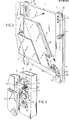
- figure 1 a perspective view of frontages coated with glass sheets using the method embodying the invention,
- figure 2 a fragmentary, perspective view of a frontage part with a glass sheet during the execution of the method embodying the invention,
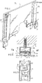
- figure 3 an enlarged, perspective view of detail III of figure 2,
- figure 4 a fragmentary, perspective view of a variant of the glass sheet that can be fastened in accordance with the invention,
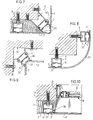
- figures 5 and 6 a front view and a plan view respectively of an alternative embodiment of the lock bolts,
- figures 7 to 11 each a horizontal sectional view of a different frontage part with a device embodying the invention,
- figure 12 a perspective view of the activity of sealing the gap between two neighbouring glass sheets.
-
Frontage parts 1 are coated withglass sheets 2, for example, as outer walls of a building 19 (figure 1). - In the
device 30 embodying the invention (figure 2) on thefrontage parts 1 metalhollow profiles 7 are fastened by means ofscrews 9. Before thehollow profiles 7 are arranged on thefrontage part 1, fastening means 21 and locking means 22 are provided. The fastening means 21 comprise hooks 43 having hook heads 4 inclined upwardly from thefrontage part 1. Ahook 3 is fixed to theprofile 7 by means of screws 24 passing through aplate 28. Supportingmeans 20 are arranged previously preferably by means of aglue layer 13 on theglass sheets 2. Preferably the supportingmeans 20 comprise vertical,U-shaped profiles 5 of metal extending along substantially the whole length of theglass sheet 2, whilst their flange substantially parallel to the glass sheet engages at the lower end of theglass sheet 2 on thehooks 3 behind hook heads 4 in lowering theglass sheet 2 in the direction of the arrow Z. Subsequently theglass sheet 2 can be tilted in the direction of the arrow K until thisglass sheet 2 is approximately in its vertical position. - The locking means 22 also previously arranged on the
profiles 7 preferably comprise (figure 3)lock bolts 6 rotatable in the direction of the arrow D when theU-profiles 5 fastened to the glass sheets in their vertical position are approximately near thehollow profiles 7. Thelock bolts 6 are held in their locking position bystops 10. Preferably thelock bolts 6 are arranged pairwise on acarrier 8 so that each of them can lock a glass sheet. Thecarrier 8 is fastened byscrews 25 to theprofile 7. Thelock bolts 6 are furthermore held by means of screws 11 in theprofiles 7 co-operating withspring rings 12 arranged between thelock bolts 6 and theprofiles 7. - The variant shown in figure 4 comprises other supporting
means 20 for theglass sheet 2, which comprise I-shaped metal profiles 105 engaging thehooks 3 and a supporting rim 14 fastened by means of a glue layer 114 to the underside of theglass sheet 2 and to the I-profiles 115. - In a further embodiment illustrated in figures 6 and 7 for the locking means 22 sliding
lock bolts 15 fasten theprofiles 5 to glass sheets in a locking manner on theprofiles 7 fastened byscrews 9 on thefrontage part 1. Thelock bolts 15 are furthermore arranged pairwise by means ofscrews 26 on acarrier 108. - Embodiments of
devices coating frontage parts profiles alternative profiles glass sheets 2 for securing theglass sheets 2 to thefrontage parts frontage parts 71 having, for example, a slidingwindow 16 can also be coated in a simple manner withglass sheets 2 by means of theprofiles 5, 7 (figure 10). - As shown in figure 11 the
device 34 embodying the invention can also be used for coating afrontage part 1 withdouble glass sheets 72. Theprofiles 75 required for supporting thedouble glass sheets 72 may have the shape of a G. Theseprofiles 75 are secured to the profiles by means of the fastening means 21 described above and the locking means 22. - After the
glass sheets board 29 behind the intermediate space 18 between twoglass sheets like substance 27 by means of aspout 17 for sealing the coating of thefrontage part 1.
Claims (8)
Priority Applications (1)
| Application Number | Priority Date | Filing Date | Title |
|---|---|---|---|
| AT85201014T ATE29546T1 (en) | 1984-06-25 | 1985-06-25 | METHOD AND DEVICE FOR ATTACHING GLASS PANES TO A FAÇADE. |
Applications Claiming Priority (2)
| Application Number | Priority Date | Filing Date | Title |
|---|---|---|---|
| NL8402004A NL8402004A (en) | 1984-06-25 | 1984-06-25 | METHOD AND APPARATUS FOR Cladding a façade piece with glass plates |
| NL8402004 | 1984-06-25 |
Publications (2)
| Publication Number | Publication Date |
|---|---|
| EP0168097A1 true EP0168097A1 (en) | 1986-01-15 |
| EP0168097B1 EP0168097B1 (en) | 1987-09-09 |
Family
ID=19844122
Family Applications (1)
| Application Number | Title | Priority Date | Filing Date |
|---|---|---|---|
| EP85201014A Expired EP0168097B1 (en) | 1984-06-25 | 1985-06-25 | Method and device for applying glass sheets on a frontage |
Country Status (8)
| Country | Link |
|---|---|
| US (1) | US4665662A (en) |
| EP (1) | EP0168097B1 (en) |
| JP (1) | JPS6114356A (en) |
| AT (1) | ATE29546T1 (en) |
| AU (1) | AU575959B2 (en) |
| DE (1) | DE3560598D1 (en) |
| HK (1) | HK35289A (en) |
| NL (1) | NL8402004A (en) |
Cited By (6)
| Publication number | Priority date | Publication date | Assignee | Title |
|---|---|---|---|---|
| GB2226589A (en) * | 1988-12-28 | 1990-07-04 | Yoshida Kogyo Kk | Windows |
| FR2769330A1 (en) * | 1997-10-07 | 1999-04-09 | Uriel Moch | DEVICE FOR CONSTRUCTING A FACADE OF PLATES |
| FR2771434A1 (en) * | 1997-11-21 | 1999-05-28 | Alcan France | Internal mounting of panel in support frame cavity |
| GB2333305A (en) * | 1998-01-19 | 1999-07-21 | Simon Joseph Kenny | Glazing unit retention for curtain walling systems |
| EP2581521A3 (en) * | 2011-10-12 | 2015-12-23 | Stefan Ehrenreich | Floorboard assembly and device for holding an end floor board |
| FR3142497A1 (en) * | 2022-11-25 | 2024-05-31 | Chanel SAS | DEVICE FOR FIXING AN INSULATION PANEL |
Families Citing this family (15)
| Publication number | Priority date | Publication date | Assignee | Title |
|---|---|---|---|---|
| US4803817A (en) * | 1987-04-24 | 1989-02-14 | Thornhill Glass & Mirror Inc. | Glazing assembly and method for glazing a building |
| US5216858A (en) * | 1989-02-24 | 1993-06-08 | Angeles Metal Systems | Vertical movement clip and C stud retainer system |
| US5115612A (en) * | 1990-03-14 | 1992-05-26 | Vacuglas, Inc. | Transparent thermal panel |
| US5836133A (en) * | 1995-06-30 | 1998-11-17 | B & D Industries, Inc. | Vertical movement clip for attaching a building member to a beam having a channel therein |
| US5640823A (en) * | 1995-06-30 | 1997-06-24 | Bergeron; Mark | Vertical movement clip for attaching a building member to a beam having a channel therein |
| US5802789B1 (en) * | 1996-12-17 | 2000-11-07 | Steelcase Inc | Partition construction including removable cover panels |
| US5924234A (en) * | 1997-11-20 | 1999-07-20 | Trijicon, Inc. | Optical sighting device |
| US6170213B1 (en) | 1998-01-13 | 2001-01-09 | Dfb Sales, Inc. | Wall panel mounting system and method |
| US5906079A (en) * | 1998-01-14 | 1999-05-25 | Steelcase, Inc. | Partition system with attached markerboard |
| US7517486B2 (en) * | 2003-05-16 | 2009-04-14 | Du Pont Performance Elastomers L.L.C. | Process for preparing UV curable sealing assemblies |
| US6967775B1 (en) * | 2004-07-13 | 2005-11-22 | Millett Industries, Inc. | Zoom dot sighting system |
| US8966842B2 (en) | 2012-09-17 | 2015-03-03 | Steelcase Inc. | Floor-to-ceiling partition wall assembly |
| US10329759B2 (en) | 2012-09-17 | 2019-06-25 | Steelcase Inc. | Floor-to-ceiling partition wall assembly |
| US10233652B1 (en) * | 2016-03-14 | 2019-03-19 | Alply Insulated Panels, LLC | Individual locking wall panel system |
| JP6999364B2 (en) * | 2017-10-31 | 2022-01-18 | Ykk Ap株式会社 | Frame |
Citations (5)
| Publication number | Priority date | Publication date | Assignee | Title |
|---|---|---|---|---|
| US2251991A (en) * | 1940-01-25 | 1941-08-12 | Porcelain Structures Inc | Supporting structure for porcelain enameled pans |
| FR1427593A (en) * | 1965-04-07 | 1966-02-04 | Economical method of hanging up facades of buildings into curtain walls, and device for implementing the method | |
| FR1486424A (en) * | 1966-05-16 | 1967-06-30 | Houilleres Bassin Du Nord | Method and device for installing insulation panels |
| FR2016357A1 (en) * | 1968-08-26 | 1970-05-08 | Glas Ag | |
| US4370838A (en) * | 1980-08-14 | 1983-02-01 | The Columbus Show Case Company | Curtain wall |
Family Cites Families (5)
| Publication number | Priority date | Publication date | Assignee | Title |
|---|---|---|---|---|
| US2480241A (en) * | 1944-07-03 | 1949-08-30 | Universal Oil Prod Co | Detachable clip suspended wall |
| US2670507A (en) * | 1950-03-24 | 1954-03-02 | Daitch Sidney | Parallel pane sash having a removable pane |
| US4194333A (en) * | 1978-05-24 | 1980-03-25 | Butler Manufacturing Company | Attachment for mounting concrete wall panels on a building |
| US4483122A (en) * | 1979-08-09 | 1984-11-20 | Ppg Industries, Inc. | Replacement panel and method of installing same in a curtainwall |
| US4543755A (en) * | 1984-01-20 | 1985-10-01 | Ppg Industries, Inc. | Curtainwall system |
-
1984
- 1984-06-25 NL NL8402004A patent/NL8402004A/en not_active Application Discontinuation
-
1985
- 1985-06-20 US US06/746,761 patent/US4665662A/en not_active Expired - Fee Related
- 1985-06-24 AU AU43998/85A patent/AU575959B2/en not_active Ceased
- 1985-06-24 JP JP60138853A patent/JPS6114356A/en active Pending
- 1985-06-25 DE DE8585201014T patent/DE3560598D1/en not_active Expired
- 1985-06-25 EP EP85201014A patent/EP0168097B1/en not_active Expired
- 1985-06-25 AT AT85201014T patent/ATE29546T1/en not_active IP Right Cessation
-
1989
- 1989-04-27 HK HK352/89A patent/HK35289A/en unknown
Patent Citations (5)
| Publication number | Priority date | Publication date | Assignee | Title |
|---|---|---|---|---|
| US2251991A (en) * | 1940-01-25 | 1941-08-12 | Porcelain Structures Inc | Supporting structure for porcelain enameled pans |
| FR1427593A (en) * | 1965-04-07 | 1966-02-04 | Economical method of hanging up facades of buildings into curtain walls, and device for implementing the method | |
| FR1486424A (en) * | 1966-05-16 | 1967-06-30 | Houilleres Bassin Du Nord | Method and device for installing insulation panels |
| FR2016357A1 (en) * | 1968-08-26 | 1970-05-08 | Glas Ag | |
| US4370838A (en) * | 1980-08-14 | 1983-02-01 | The Columbus Show Case Company | Curtain wall |
Cited By (13)
| Publication number | Priority date | Publication date | Assignee | Title |
|---|---|---|---|---|
| GB2226589A (en) * | 1988-12-28 | 1990-07-04 | Yoshida Kogyo Kk | Windows |
| US5036640A (en) * | 1988-12-28 | 1991-08-06 | Yoshida Kogyo K.K. | Window |
| AU628449B2 (en) * | 1988-12-28 | 1992-09-17 | Yoshida Kogyo K.K. | Window |
| GB2226589B (en) * | 1988-12-28 | 1993-03-10 | Yoshida Kogyo Kk | Window |
| FR2769330A1 (en) * | 1997-10-07 | 1999-04-09 | Uriel Moch | DEVICE FOR CONSTRUCTING A FACADE OF PLATES |
| EP0908580A1 (en) * | 1997-10-07 | 1999-04-14 | MOCH, Uriel, Pierre | Apparatus for constructing a façade made of panels |
| FR2771434A1 (en) * | 1997-11-21 | 1999-05-28 | Alcan France | Internal mounting of panel in support frame cavity |
| GB2333305A (en) * | 1998-01-19 | 1999-07-21 | Simon Joseph Kenny | Glazing unit retention for curtain walling systems |
| US6269601B1 (en) | 1998-01-19 | 2001-08-07 | Simon Joseph Kenny | Glazing assembly |
| GB2333305B (en) * | 1998-01-19 | 2002-03-27 | Simon Joseph Kenny | A glazing assembly |
| US6401410B2 (en) | 1998-01-19 | 2002-06-11 | Simon Joseph Kenny | Glazing assembly |
| EP2581521A3 (en) * | 2011-10-12 | 2015-12-23 | Stefan Ehrenreich | Floorboard assembly and device for holding an end floor board |
| FR3142497A1 (en) * | 2022-11-25 | 2024-05-31 | Chanel SAS | DEVICE FOR FIXING AN INSULATION PANEL |
Also Published As
| Publication number | Publication date |
|---|---|
| US4665662A (en) | 1987-05-19 |
| ATE29546T1 (en) | 1987-09-15 |
| HK35289A (en) | 1989-05-05 |
| AU575959B2 (en) | 1988-08-11 |
| NL8402004A (en) | 1986-01-16 |
| DE3560598D1 (en) | 1987-10-15 |
| AU4399885A (en) | 1986-01-02 |
| EP0168097B1 (en) | 1987-09-09 |
| JPS6114356A (en) | 1986-01-22 |
Similar Documents
| Publication | Publication Date | Title |
|---|---|---|
| EP0168097B1 (en) | Method and device for applying glass sheets on a frontage | |
| EP0084209B1 (en) | Interior partition wall system | |
| US5644877A (en) | Demountable ceiling closure | |
| US5487244A (en) | Shutter system and method | |
| US3537219A (en) | Demountable partition wall | |
| EP1387016B1 (en) | Ceiling paneling system | |
| US3828495A (en) | Partition with concealed slotted standard | |
| US5038534A (en) | Unitary panel module and connector | |
| CA1299023C (en) | Basic unit for the erection of a sliding-door | |
| US4034513A (en) | Structural members for panel wall and door mounting | |
| EP3618598B1 (en) | Hot/cold aisle system | |
| US3977144A (en) | Suspended ceiling structure, particularly for dry-wall type panels | |
| GB999443A (en) | Improvements in prefabricated buildings | |
| US5005315A (en) | Multi-panel sliding closure unit | |
| US3408781A (en) | Partition and method of tilting into position | |
| US2766858A (en) | Demountable metal partitions | |
| US3391723A (en) | Folding door assembly and mounting units therefor | |
| US3358410A (en) | Glazing post, cornice and rail cap and assembly thereof | |
| US2664978A (en) | Means for mounting metal wall panels | |
| US2085281A (en) | Metal building structure and method of assembling the same | |
| US3340662A (en) | Suspended ceiling with cup type cap | |
| US2755893A (en) | Gutter board for building composed of prefabricated panels | |
| US4512118A (en) | Casing arrangement for partition end caps | |
| US2821738A (en) | Track for rolling door | |
| CA2270941C (en) | Wall for the booth of a coating plant |
Legal Events
| Date | Code | Title | Description |
|---|---|---|---|
| PUAI | Public reference made under article 153(3) epc to a published international application that has entered the european phase |
Free format text: ORIGINAL CODE: 0009012 |
|
| AK | Designated contracting states |
Designated state(s): AT BE CH DE FR GB IT LI LU NL SE |
|
| 17P | Request for examination filed |
Effective date: 19860213 |
|
| 17Q | First examination report despatched |
Effective date: 19861009 |
|
| ITF | It: translation for a ep patent filed | ||
| GRAA | (expected) grant |
Free format text: ORIGINAL CODE: 0009210 |
|
| AK | Designated contracting states |
Kind code of ref document: B1 Designated state(s): AT BE CH DE FR GB IT LI LU NL SE |
|
| REF | Corresponds to: |
Ref document number: 29546 Country of ref document: AT Date of ref document: 19870915 Kind code of ref document: T |
|
| REF | Corresponds to: |
Ref document number: 3560598 Country of ref document: DE Date of ref document: 19871015 |
|
| ET | Fr: translation filed | ||
| PLBE | No opposition filed within time limit |
Free format text: ORIGINAL CODE: 0009261 |
|
| STAA | Information on the status of an ep patent application or granted ep patent |
Free format text: STATUS: NO OPPOSITION FILED WITHIN TIME LIMIT |
|
| 26N | No opposition filed | ||
| PGFP | Annual fee paid to national office [announced via postgrant information from national office to epo] |
Ref country code: DE Payment date: 19910628 Year of fee payment: 7 |
|
| ITTA | It: last paid annual fee | ||
| PGFP | Annual fee paid to national office [announced via postgrant information from national office to epo] |
Ref country code: NL Payment date: 19910630 Year of fee payment: 7 |
|
| PGFP | Annual fee paid to national office [announced via postgrant information from national office to epo] |
Ref country code: BE Payment date: 19910918 Year of fee payment: 7 |
|
| PGFP | Annual fee paid to national office [announced via postgrant information from national office to epo] |
Ref country code: GB Payment date: 19910920 Year of fee payment: 7 |
|
| PGFP | Annual fee paid to national office [announced via postgrant information from national office to epo] |
Ref country code: AT Payment date: 19910925 Year of fee payment: 7 Ref country code: CH Payment date: 19910925 Year of fee payment: 7 |
|
| PGFP | Annual fee paid to national office [announced via postgrant information from national office to epo] |
Ref country code: FR Payment date: 19910926 Year of fee payment: 7 |
|
| EPTA | Lu: last paid annual fee | ||
| PG25 | Lapsed in a contracting state [announced via postgrant information from national office to epo] |
Ref country code: AT Effective date: 19920625 Ref country code: GB Effective date: 19920625 |
|
| PG25 | Lapsed in a contracting state [announced via postgrant information from national office to epo] |
Ref country code: CH Effective date: 19920630 Ref country code: LI Effective date: 19920630 Ref country code: BE Effective date: 19920630 |
|
| PGFP | Annual fee paid to national office [announced via postgrant information from national office to epo] |
Ref country code: LU Payment date: 19920630 Year of fee payment: 8 |
|
| PGFP | Annual fee paid to national office [announced via postgrant information from national office to epo] |
Ref country code: SE Payment date: 19921229 Year of fee payment: 8 |
|
| BERE | Be: lapsed |
Owner name: GLASFABRIEK SAS VAN GENT B.V. Effective date: 19920630 |
|
| PG25 | Lapsed in a contracting state [announced via postgrant information from national office to epo] |
Ref country code: NL Effective date: 19930101 |
|
| NLV4 | Nl: lapsed or anulled due to non-payment of the annual fee | ||
| GBPC | Gb: european patent ceased through non-payment of renewal fee |
Effective date: 19920625 |
|
| PG25 | Lapsed in a contracting state [announced via postgrant information from national office to epo] |
Ref country code: FR Effective date: 19930226 |
|
| REG | Reference to a national code |
Ref country code: CH Ref legal event code: PL |
|
| PG25 | Lapsed in a contracting state [announced via postgrant information from national office to epo] |
Ref country code: DE Effective date: 19930302 |
|
| REG | Reference to a national code |
Ref country code: FR Ref legal event code: ST |
|
| PG25 | Lapsed in a contracting state [announced via postgrant information from national office to epo] |
Ref country code: LU Free format text: LAPSE BECAUSE OF NON-PAYMENT OF DUE FEES Effective date: 19930625 |
|
| PG25 | Lapsed in a contracting state [announced via postgrant information from national office to epo] |
Ref country code: SE Effective date: 19930626 |
|
| EUG | Se: european patent has lapsed |
Ref document number: 85201014.9 Effective date: 19940110 |