EP0168054B1 - Method and system for data driven information processing - Google Patents
Method and system for data driven information processing Download PDFInfo
- Publication number
- EP0168054B1 EP0168054B1 EP85108647A EP85108647A EP0168054B1 EP 0168054 B1 EP0168054 B1 EP 0168054B1 EP 85108647 A EP85108647 A EP 85108647A EP 85108647 A EP85108647 A EP 85108647A EP 0168054 B1 EP0168054 B1 EP 0168054B1
- Authority
- EP
- European Patent Office
- Prior art keywords
- input
- output
- data
- processing
- information
- Prior art date
- Legal status (The legal status is an assumption and is not a legal conclusion. Google has not performed a legal analysis and makes no representation as to the accuracy of the status listed.)
- Expired - Lifetime
Links
Images


Classifications
-
- G—PHYSICS
- G06—COMPUTING; CALCULATING OR COUNTING
- G06F—ELECTRIC DIGITAL DATA PROCESSING
- G06F9/00—Arrangements for program control, e.g. control units
- G06F9/06—Arrangements for program control, e.g. control units using stored programs, i.e. using an internal store of processing equipment to receive or retain programs
- G06F9/44—Arrangements for executing specific programs
- G06F9/448—Execution paradigms, e.g. implementations of programming paradigms
- G06F9/4494—Execution paradigms, e.g. implementations of programming paradigms data driven
Definitions
- This invention relates to a stored program controlled data processing system, and more specifically to the data driven type control of such a system.
- the data driven (or data flow) type control method is to control a processing sequence depending upon the flow of data, i.e., depending upon the preparation situation of data that are to be processed, and has hitherto been studied in order to realize a so-called non-Neumann type computer (see “Trend of Data Flow Computers Innovating the Construction of Computers", Part 1, Nikkei Electronics, May 28, 1979, pp. 64-81).
- the data driven non-Neumann type computer has an architecture which is fundamentally different from a conventional so-called Neumann type computer, i.e. a computer in which a program is sequentially executed in a predetermined single stream (or referred to as the sequential execution type computer in this specification), and is designed in an attempt to increase data processing ability by means of parallel processing. For operations which do not require such high processing abilities, therefore, the data driven non-Neumann type computer becomes very expensive, and is not always ideal.
- the conventional sequential execution type machine has various difficulties not only with respect to the data processing ability but also to the preparation of software.
- the data driven type control is advantageous since it clarifies correlations of input and output data among various portions of the program and clarifies execution conditions of various portions, making it possible to easily comprehend the whole construction of the program and, accordingly, to easily develop software and to effect debugging and modifications.
- U.S. patent No. 3,662,401 discloses a method for controlling a sequential execution type processor or processors to execute program tasks in a data driven manner.
- each program task is associated with a list of control data, referred to as a program control instruction (PCI), which includes an input field specifiying the sources of required input data, an output field specifying the destinations of output data, an E list specifying other program tasks, or their associated PCIs of which the execution depends on the completion of this particular program task, and a count field indicating the number of program tasks that must be completed before this particular program task is started.
- PCI program control instruction
- Each program task when started, fetches required input data from the sources specified by the input field of the associated PCI, and stores output data into the destinations specified by the output field of the associated PCI.
- the count field is decremented by "1" in each PCI specified by the E list of this completed program task.
- the count field of a PCI associated with another program task is reduced to "0", and this program task is then ready to start.
- a series of program tasks are executed in a data driven manner while instructions within each task are executed conventionally in the programmed sequence.
- This type of control is advantageous in that substantial data driven processing is achieved by a conventional sequential machine with small overhead. Although great difficulty is encountered in producing a complicated large-scale program, it is rather easy to produce independent small-scale programs (consisting of several hundred steps or less in machine language). Therefore, the above-described type of control permits programmers to substantially enjoy the advantage of data driven logic in designing a large-scale program by linking independent small-scale program modules of the conventional sequential type. Thus, input conditions and starting conditions for various program modules are clarified, and the order of description of program modules is free from the order of execution of them, whereby the production and maintenance of large-scale software are remarkably facilitated.
- An object of the present invention is to improve data driven processing method and system of the above-described type so that branching is carried out efficiently and correctly.
- Another object of the present invention is to improve data driven processing method and system of that type so that overhead for initializing and updating control data is diminished.
- I/O prescription tables are prepared in a memory, each of the I/O prescription tables being associated with a processing program module, and containing input data source information, input situation information, output notice destination information, and output data storage area for the associated processing program modules.
- the processing program module makes reference to its associated table, reads the input data according to the input source information, performs a predetermined processing of the sequential execution type, and writes the resultant output data on the output data storage area in the table.
- the execution control program makes reference to the same table, and updates the input situation information in the designated tables so as to indicate that the corresponding input data are prepared.
- the execution control program registers a table which is furnished with all of the required input data at the tail of a queue, successively fetches tables waiting in the queue in order starting from the head thereof, and actuates the associated processing program modules.
- each output data storage area has an associated validity information area
- the processing program module stores information indicating validity of the stored output data into the validity information area corresponding to the stored output data used in a selected program branch.
- the execution control program then updates the input situation information only for the output data the validity of which is indicated by the validity indicating information.
- only the input situation information of the processing program modules that are included in the selected program branch is updated, while the input situation information of all other processing program modules that failed to be branched to is kept unchanged, whereby branching is carried out efficiently and correctly.
- Another characteristic of the present invention resides in its unique procedure of initializing and updating the input situation information.
- the input situation information for this processing program module is set just at this needed number.
- the input situation information is set at a value "1" even if no output data is needed.
- the input situation information is decremented only when its value is "2" or more, and it is left unaltered when its value is "l".
- the execution control program selects for execution a processing program module whose input situation information value is "l" at the start of the updating operation.
- This control method can be executed by a data processing system having a single processor of the sequential execution type.
- a processing unit for executing processing program modules may be provided separately from a processing unit for execution control.
- a plurality of processing units may be provided for executing groups of processing program modules, together with a plurality of table memories and queue memories respectively associated therewith.
- memories may advantageously be employed in combination.
- at least a portion of the processing program modules and a portion of the execution control program may be stored in memories which can operate faster than those which store I/0 prescription tables and the queue.
- a portion of the I/0 prescription tables which need not be altered may be held in a read-only memory, while the remaining portion thereof may be held in an ordinary rewritable memory.
- the present invention realizes data driven processing using a conventional machine or machines of the sequential execution type with ease and a minimal increase in overhead, as compared with the prior art.
- program branching is carried out efficiently and correctly, and overhead for updating and reinitialising control data is remarkably diminished.
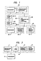
- Fig. l shows a data processing system for implementing the control method of the present invention.
- this system consists of a processing unit l0 for processing data, a memory 20 for I/O prescription table (I/O PTBL) for the data driven type control, a processing unit 30 for execution control, and a memory 40 for start waiting queue.
- I/O PTBL I/O prescription table
- the processing unit 10 for processing data consists of a sequential execution type processor l0-l, a memory l0-2 which stores a plurality of small and independent processing program modules, an interface circuit l0-3 for communication with the processing unit 30 for execution control, and a processor bus l0-4 coupling them.
- the memory 20 for input/output prescription table (I/O PTBL) holds I/O PTBL's 20-1 respectively associated with the processing program modules, and each I/O PTBL contains program identifying information (program number, starting address, etc.), input data preparation situation indicating information, input data designating information (address or literal), output data storage area, output notice destination designating information, and any other information related to the input and output of its associated processing program module.
- the processing unit 30 for execution control consists of a sequential execution type processor 30-l, a memory 30-2 which stores an execution control program, an interface circuit 30-3 for communication with the processing unit 10 for processing data, and a processor bus 30-4 that connects them.
- the processor bus 30-4 and the processor bus 10-4 in the data processing unit 10 are also connected to the memory 20 which stores I/O PTBL's.
- the memory 40 for start waiting queue is connected to the processor bus 30-4 in the processing unit for execution control, and provides a start waiting queue 40-l which registers, in the form of FIFO, the addresses of I/O PTBL's associated with program modules which are furnished with the whole input data.
- the processing unit 30 for execution control scans the I/O PTBL's 20-l. When a table furnished with the whole input data is found, the address of this table is registered at the end of the start waiting queue 40-l. When the scanning for the whole tables is finished, the processing unit 30 for execution control fetches the address of a starting table at the beginning of the queue, reads from this table information identifying the associated processing program module, and sends the information together with the address of this table to the data processing unit l0 via the interface circuit 30-3.
- the data processing unit l0 Upon receipt of these information via the interface circuit l0-3, the data processing unit l0 executes the processing program by making reference to the associated I/O PTBL using input data designated thereby, and writes the output data into a predetermined area of the table. Then, the data processing unit 10 informs the processing unit 30 for execution control of the completion of processing via the interface circuit l0-3.
- the processing unit 30 for execution control Upon receipt of this information via the interface circuit 30-3, the processing unit 30 for execution control initiates the execution control program, examines the associated I/O PTBL 20-l, and resets the input data preparation situation indicator in the I/O PTBL's of all of the output notice destinations designated thereby. If there is a processing program module furnished with the whole input data, the processing unit 30 for execution control registers it in the start waiting queue 40-l.
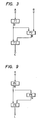
- Fig. 2 shows a system consisting of a sequential execution type processor 5l, a memory ll for storing processing programs, a memory 2l for storing I/O prescription tables, a memory 3l for storing a execution control program, and a memory 4l for storing a start waiting queue, that are connected to one another through a processor bus 6l.
- the thus constructed system also realizes the data driven type control which is essentially the same as the above-mentioned one, since the processing program and the execution control program are alternately executed by the processor 5l. It is allowable to store the contents of these memories ll,21,31 and 41 in the respective areas of a single memory unit, as a matter of course.
- Fig. 3 shows a simple data driven type program to which the present invention is adapted.
- This as a whole is a program which effects the processing on the input data A and B to obtain a resultant output data C.
- the substance of processing is represented by the combination of small and independent processing program modules Fl, F2 and F3.
- the delivery and reception of data among the processing program modules are indicated by arrow lines.
- the substances of processing program modules Fl to F3 are realized by ordinary sequential execution type programs which are executed when necessary input data are all furnished independently of the designation of the program counter or the description order (or storage positions) of the programs, unlike the ordinary sequential execution type program.
- processing program module Fl is readily executed provided there exists the input data A, and the processing program module F2 is started when there exists the input data B and also the processing program module Fl has finished the production of output D.
- the processing program module F3 is not started until the processing program module F1 and the processing program module F2 have finished the production of output data D and E, respectively.
- I/O prescription table I/O PTBL
- Every processing program module possesses an associated I/O PTBL.
- An I/O PTBL 200 associated with a processing program module has respective areas for a linkage pointer (LINKPT) 20l for forming a start waiting queue, an identifier (program name, program number, or starting address) 202 for identifying the associated processing program module, an input data number 203, an input situation indicator 204 for indicating the preparation situation of input data, an output data number 205, an input data class 206, an input data designator (literal data or address) 207, an output data validity indicator 208, an output notice destination number 209, an output data storage 2l0, and an output notice destination designator 211.
- LINKPT linkage pointer
- Sets of areas 206 and 207 are provided in the number of input data required for the associated program, the areas 211 are provided in the number of notice destinations for each output data, and sets of the areas 208 to 211 are provided in the number of all output data that are produced by the associated program.
- the linkage pointer 20l and the output data validity indicator 208 will be described later. No explanation will be necessary for the program identifier 202, input data number 203, output data number 205 and output data storage 2l0.
- the input situation indicator 204 contains a group of flag bits each being alotted to each of the input data, and the level “l” indicating that the associated input data has not yet been formed, and the level "0" indicating that the associated input data has been formed already. As will be described later, however, any other form may be employed.
- the input data class 206 consists of a l-bit flag which assumes "0" when the associated input data is a fixed data (such as a constant) that has been given in advance, and which assumes "1" when the associated input data is an output data of another program.
- the data itself has been written beforehand onto the input data indicator area 207.
- an address from which the data is to be read i.e. the address of output data storage 2l0 of I/O PTBL associated with the processing program module that produces the data
- an address from which the data is to be read i.e. the address of output data storage 2l0 of I/O PTBL associated with the processing program module that produces the data
- the output notice destination number area 209 has been stored the number of processing program modules that require the associated output data as input data, and on the output notice destination designator area 211 has been written the address of the I/O PTBL (more specifically the position of the corresponding bit of the input situation indicator 204) associated with a processing program module which is an output notice destination.
- These information except 201, 204, 208 and 210, are all fixed information that have been determined at the stage of programming. However, the initial value of the indicator 204 has been determined in advance.
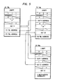
- Fig. 5 shows I/O PTBL's for the data driven type program of Fig. 3.
- the first processing program module (hereinafter simply referred to as program) Fl has only the input data A (literal) that is given in advance, and produces the output data D only, which is to be used as a first input data to the program F2 and a first input data to the program F3.
- program number (202) l
- input data number (203) l
- initial value of input situation indicator (204) "00000000”
- output data number (205) l
- first input data class (206) "0”
- first input data designator (207) 'A' (literal)
- output notice destination number (209) of first output data 2
- output notice destination (2ll) of first output data F2TBL address and F3TBL address.
- the second program F2 receives a first input data which is produced by the program Fl, receives a second input data B (literal) that has been given in advance, and produces the data of which the number is l and which is used as a second input data for the program F3.
- program number (202) 2
- input data number (203) 2
- initial value of input situation indicator (204) "00000001”
- output data number (205) l
- first input data class (206) "l”
- first input data designator (207) OUT ll address (address of first output data storage of FlTBL)
- second input data class (206) "0”
- second input data designator (207) 'B' (literal)
- output notice destination number (209) of first output data l
- the third program F3 receives a first input data produced by the program Fl, receives a second input data produced by the program F2, and produces a single output data.
- the start waiting queue (40-1, 41, hereinafter represented by 41) may be an ordinary FIFO memory. According to this embodiment, however, the queue is linked by a linkage pointer (201 of Fig. 4) of I/O PTBL in order to simplify the construction of the queue.
- the start waiting queue 4l is simply equipped with a head pointer 40l and a tail pointer 402.
- the head pointer 40l holds the address of I/O PTBL (TBLl) 200-l at the beginning the queue.
- the linkage pointer 20l-l of TBL 1 holds the address of I/O PTBL (TBL2) in the next place in the queue, and so on.
- the linkage pointer 20l-3 of I/O PTBL (TBL3) at the end of the queue holds "0" to indicate that there exists no further link.
- the tail pointer 402 in the start waiting queue 41 holds the address of I/O PTBL (TBL3) at the end.
- An I/O PTBL is fetched from the queue by reading the contents of the head pointer 401. Then, the contents of the head pointer 401 is replaced by the contents of the linkage pointer of I/O PTBL that has just been read out (adress of TBL2 held in TBL 1 in the diagrammed example).
- An I/O PTBL can be newly registered in the queue by writing its address onto both the tail pointer 402 and the linkage pointer 20l-3 of I/O PTBL (TBL3) located at the tail. At the same time, the linkage pointer of I/O PTBL that is newly registered is set to "0".
- the execution control program 3l examines (step 7l) the head pointer 40l of start waiting queue 4l, reads the contents thereof (the address of F1TBL in this example) (step 72), makes reference to the corresponding table based thereupon to determine from the program number 202 that the program to be started is the program Fl, and hands the control over to the program Fl (step 73).
- the program Fl makes rererence to F1TBL, and detects that the number of input data is one, and that it is the one stored in the input data designator area 207, since the input data number 203 is "1" and the input data class 206 is "0".
- the program Fl reads 'A' from the area 207 and performs a predetermined operation.
- the program Fl stores the result of operation, i.e. stores 'D', in the OUT 11 which is the first output data storage 210, and returns the control back to the execution control program 31 (step 74) when the program is finished.
- the execution control program 31 then makes reference to the I/O PTBL associated with the program Fl that has just been executed, i.e. makes reference to the F1TBL. Then, in accordance with the output notice destination designator 211, the execution program 31 resets (step 75) the corresponding bits in the input situation indicator 204 in the F2TBL and F3TBL to "0". When there is an I/O FTBL in which the input situation indicator 204 is all "0", it (F2TBL in this example) is registered (step 70) in the start waiting queue 4l.
- the execution control program 3l decides that the whole processing is finished, and sets the bits in the input situation indicator 204 corresponding to input data from other programs to "l" for all I/O PTBL's relying upon the input data number 203 and the input data class 206, and then resumes the initial condition.
- the input situation indicator 204 may be a counter.
- the input data number 203 does not represent the number of all input data but represents the number of output data only of other programs, and this number is set as an initial value of the counter and is counted down in response to the output notice operation. When the counted value has reached a predetermined value, it is decided that the necessary input data are all furnished. An embodiment of this type will be mentioned later.
- the input data are furnished nearly in a predetermined order. Those which may be furnished last are, in many cases, limited to particular minority data. In such a case, the number of data that are likely to be furnished last is employed as the input data number 203, and the initial condition of input situation indicator 204 is set correspondingly. Furthermore, the output notice destination number 209 and the output notice destination designator 2ll are set for those data that are likely to be furnished last. According to this method, the overhead can be reduced for the output notice operation.
- the output notice destination differs depending upon the direction of branch, and the I/O PTBL requires output data areas (208 to 21l in Fig. 4) of a number equal to the number of branches.
- the output notice operation is executed for only the output data area that corresponds to a selected branch.
- the output data validity indicator 208 is provided to deal with such a situation. According to the processing program, "1" is set in the output data validity indicator 208 in the output data area corresponding to the selected branch when the output data is stored in the output data storage 2l0, and the control is returned to the execution control program. As shown in Fig.
- the execution control program examines as many output data areas as is indicated by the output data number 205, examines the output data validity indicator 208 (steps 81 to 84), and performs the output notice operation (steps 85 to 89) for only those outputs of which the output data validity indicator 208 is "1".
- the input situation indicator 204 functions as a counter, and holds only the number of necessary outputs of other processing programs as its initial value.
- the initial value of the input situation indicator 204 for the program that does not need outputs of other programs is forcibly set to "1".
- the initial setting of all input situation indicators that should have the initial value "1" can be effected at the time of setting up the system.
- the execution control program 31 sets the designated initial value for only the input situation indicators in which the designated initial value is "2" or greater.
- the execution control program 31 registers the I/O PTBL associated with a particular program which is predetermined to be started first at the head of the start waiting queue 41.
- the execution control program 31 examines the associated I/O PTBL 21, and checks the values of input situation indicators 204 of all output notice destinations that are indicated. If the value is greater than "1", it is decreased by "1". However, if the value is "1", the execution control program 31 decides that the required input data are all ready, and registers the associated I/O PTBL at the tail of the start waiting queue 41 without decreasing the value.
- Fig. 9 shows another data driven type program which is fundamentally the same as the program shown in Fig. 3, except that the input data B is not included.
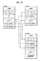
- Fig. l0 shows I/O PTBL's for the program of Fig. 9, which are also fundamentally the same as those of Fig. 5.
- the form of input situation indicator 204 is different from that of Fig. 5.
- the program F4 has only one fixed input data K, the input situation indicator (hereinafter called input situation counter as far as this modification is concerned) of its associated I/O PTBL (F4TBL) contains the initial value "l".
- the program F5 needs, as its sole input data, the output data M produced by the program F4.
- the input situation counter of its associated I/O PTBL contains the initial value "l".
- the program F6 needs, as its input data, the output data M of the program F4 and the output data N of the program F5. Therefore, "2" must be initially set in the input situation counter of its associated I/O PTBL (F6TBL).
- the input data number 203 contains the same value as the initial value of the input situation counter.
- the execution control program 31 sets predetermined initial values in those input situation counters 204 that have designated initial values of 2 or more among the I/O PTBL's 21 associated with the processing program modules 11 that are to be executed (step 90 in Fig. 11).
- "1" has been set as the initial value in the input situation counters of all I/O PTBL's.
- "2" is set as an initial value in the input situation counter of F6TBL.
- the execution control program 31 examines the head pointer 401 of the start waiting queue 41 (step 92), takes out the contents (address of F4TBL in this example) (step 93), makes reference to the corresponding table based thereupon to learn from the program number 202 that the program F4 is the one that is to be started, and hands the control over to the program F4 (step 94).
- the program F4 makes reference to F4TBL to examine the input data areas (all sets of areas 206 and 206), detects that the number of input data is one which is the data stored in the input data designator area 207, and reads 'K' therefrom to perform the predetermined operation.
- the program F4 stores 'M' which is the result of operation in the first output data storage 210, i.e. in OUT 41, and sets "1" in the output data validity indicator 208.
- the processing program F4 returns the control back to the execution control program 3l.
- the execution control program 3l makes reference to F4TBL which is the I/O PTBL associated with the processing program F4 that has just been executed.
- the execution control program 3l then reads the input situation counters 204 of F5TBL and F6TBL according to the output notice destination designators 211 that accompany the output data whose output data validity indicators 208 have been set to "1" (step 95).
- the execution control program 3l decides whether the input situation indicators 204 are "l” or not (step 96). If there is any I/O PTBL that contains "l", it (F5TBL in this example) is registered in the start waiting queue 4l (step 97).
- the input situation counter 204 (input situation counter of F6TBL in this example) having such a value is decreased by "1", and is thus updated (step 98). Thereafter, the programs F5 and F6 are executed in like manner. When it is detected that there is no I/O PTBL that has been registered in the start waiting queue 4l (step 92), the execution control program 31 decides that the whole processing is completed.
- the execution control program need not decrease the input situation counter. Further, at the time of initial setting, it is necessary to operate only on those I/O PTBL's that require two or more outputs of other programs. Therefore, where most of the processing programs need only one output of other programs as an input, the processing time of the execution control program can be greatly reduced, making it possible to minimize the reduction of processing ability of the system caused by the intervention of execution control program.
- the information contained in the I/O PTBL can be classified into fixed information and variable information as described earlier. Therefore, the information may be separated, the the fixed information may be stored in a read-only memory.
- Fig. 12 shows the construction of I/O PTBL in such a case.
- a fixed information area 200A is contained in a read-only memory, and a variable information area 200B is contained in an ordinary rewritable memory. To maintain linkage between these two areas, the fixed information area 200A is provided with a region 220 that holds the address of variable information area 200B.
- Other reference numerals denote the same portions as those of Fig. 4. This arrangement is not suited for a general-purpose machine, but is suited for a special-purpose machine (such as electronic switching control machine). Use of the read-only memory helps increase the reliability and the operation speed.
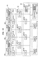
- Fig. 13 show a developed form of the system of Fig. 1, which includes three processing units for data processing 10A, 10B and 10C, and, in association therewith, input/output prescription tables (I/O PTBL's) 20-1A to 20-1C, start waiting queues 40-1A to 40-1C, and interface circuits 30-3A to 30-3C in the processing unit for execution control.
- the processing unit 30 for execution control successively examines the I/O PTBL's 20-1A, 20-1B and 20-1C. When a table furnished with all of the input data is found, the processing unit 30 registers it in one of the start waiting queues 40-1A, 40-1B, 40-1C associated therewith.
- An indicator 30-5 is provided to indicate the operating state of the data processing units 10-1A to 10-1C.
- the processing unit 30 for execution control makes reference to the indicator 30-5, fetches an I/O PTBL from the start waiting queue associated with a data processing unit that is not in operation, causes this processing unit to operate, and sets the corresponding indication in the 5 indicator 30-5. This indication is reset when the completion of processing is reported from the processing unit. It is pointed out that the data processing units of any number can be provided.
- FIG. 14 shows this modification, wherein the execution control program 11-1 and processing programs 11-2 are grouped into a block 11-5, and the start waiting queue 11-3 and I/O PTBL's 11-4 are grouped into another block 11-6.
- the total amount of memories for the two blocks will be about two megabytes, wherein the block ll-5 occupies about 40 kilobytes which is about 2 % of the total amount.
- the block ll-5 occupies about 20 to 25 kilosteps among the total of about 40 kilosteps.
Description
- This invention relates to a stored program controlled data processing system, and more specifically to the data driven type control of such a system. (2) Description of the Prior Art
- The data driven (or data flow) type control method is to control a processing sequence depending upon the flow of data, i.e., depending upon the preparation situation of data that are to be processed, and has hitherto been studied in order to realize a so-called non-Neumann type computer (see "Trend of Data Flow Computers Innovating the Construction of Computers",
Part 1, Nikkei Electronics, May 28, 1979, pp. 64-81). The data driven non-Neumann type computer has an architecture which is fundamentally different from a conventional so-called Neumann type computer, i.e. a computer in which a program is sequentially executed in a predetermined single stream (or referred to as the sequential execution type computer in this specification), and is designed in an attempt to increase data processing ability by means of parallel processing. For operations which do not require such high processing abilities, therefore, the data driven non-Neumann type computer becomes very expensive, and is not always ideal. - On the other hand, the conventional sequential execution type machine has various difficulties not only with respect to the data processing ability but also to the preparation of software. Regarding the latter point, the data driven type control is advantageous since it clarifies correlations of input and output data among various portions of the program and clarifies execution conditions of various portions, making it possible to easily comprehend the whole construction of the program and, accordingly, to easily develop software and to effect debugging and modifications.
- When high data processing ability is not required, a compromised proposal is to prepare such a program which operates the conventional sequential execution type machine in the data driven type mode. However, an excess overhead results from the procedure which checks whether the required operands are prepared for the individual operation instructions and which indicates, every time an instruction is executed, the preparation of an operand for every instruction requiring as its operand the data produced by the execution. Therefore, such is not practicable. Further, to transfer the data produced by every instruction to operand address locations of all instructions that require the produced data causes the quantity of memory access to increase and the processing speed to decrease.
- U.S. patent No. 3,662,401 discloses a method for controlling a sequential execution type processor or processors to execute program tasks in a data driven manner. According to this method, each program task is associated with a list of control data, referred to as a program control instruction (PCI), which includes an input field specifiying the sources of required input data, an output field specifying the destinations of output data, an E list specifying other program tasks, or their associated PCIs of which the execution depends on the completion of this particular program task, and a count field indicating the number of program tasks that must be completed before this particular program task is started. Each program task, when started, fetches required input data from the sources specified by the input field of the associated PCI, and stores output data into the destinations specified by the output field of the associated PCI. When a program task is completed, the count field is decremented by "1" in each PCI specified by the E list of this completed program task. In due course, the count field of a PCI associated with another program task is reduced to "0", and this program task is then ready to start. Thus a series of program tasks are executed in a data driven manner while instructions within each task are executed conventionally in the programmed sequence.
- This type of control is advantageous in that substantial data driven processing is achieved by a conventional sequential machine with small overhead. Although great difficulty is encountered in producing a complicated large-scale program, it is rather easy to produce independent small-scale programs (consisting of several hundred steps or less in machine language). Therefore, the above-described type of control permits programmers to substantially enjoy the advantage of data driven logic in designing a large-scale program by linking independent small-scale program modules of the conventional sequential type. Thus, input conditions and starting conditions for various program modules are clarified, and the order of description of program modules is free from the order of execution of them, whereby the production and maintenance of large-scale software are remarkably facilitated.
- However, a processing flow through program tasks or program modules often branches depending on various conditions. In a PCI that is associated with a branching program task, the E list must specify all program tasks to which the program may happen to branch. Then, upon completion of such a branching program task, a control program would decrement the count fields of all those possibly-branched program tasks. This is not only wasteful but also liable to cause erroneous branches since any program task can be executed as long as its count field has reached "0". Above-mentioned U.S. patent 3,662,401 does not teach how to cope with such a situation.
- In addition, the count fields of all the PCIs must be initialized to respective predetermined values. As a result, where several program tasks are to be executed many times repeatedly, the system performance is considerably reduced due to overhead for such repeated initializing operations.
- An object of the present invention is to improve data driven processing method and system of the above-described type so that branching is carried out efficiently and correctly.
- Another object of the present invention is to improve data driven processing method and system of that type so that overhead for initializing and updating control data is diminished.
- In a data processing system which comprises a sequential execution type processor, according to the present invention, I/O prescription tables are prepared in a memory, each of the I/O prescription tables being associated with a processing program module, and containing input data source information, input situation information, output notice destination information, and output data storage area for the associated processing program modules. When started, the processing program module makes reference to its associated table, reads the input data according to the input source information, performs a predetermined processing of the sequential execution type, and writes the resultant output data on the output data storage area in the table. Then, the execution control program makes reference to the same table, and updates the input situation information in the designated tables so as to indicate that the corresponding input data are prepared. Further, the execution control program registers a table which is furnished with all of the required input data at the tail of a queue, successively fetches tables waiting in the queue in order starting from the head thereof, and actuates the associated processing program modules.
- The present invention is particularly characterized in that each output data storage area has an associated validity information area, and the processing program module stores information indicating validity of the stored output data into the validity information area corresponding to the stored output data used in a selected program branch. The execution control program then updates the input situation information only for the output data the validity of which is indicated by the validity indicating information. Thus, only the input situation information of the processing program modules that are included in the selected program branch is updated, while the input situation information of all other processing program modules that failed to be branched to is kept unchanged, whereby branching is carried out efficiently and correctly.
- Another characteristic of the present invention resides in its unique procedure of initializing and updating the input situation information. When a processing program module needs two or more output data of other program modules as its input data, the input situation information for this processing program module is set just at this needed number. On the other hand, when one or no output data of other processing program modules is needed, the input situation information is set at a value "1" even if no output data is needed. In updating operation, the input situation information is decremented only when its value is "2" or more, and it is left unaltered when its value is "l". The execution control program selects for execution a processing program module whose input situation information value is "l" at the start of the updating operation. Thus, not only the operation of decrementing the input situation information value from "1" to "0" is omitted, but also the operation of reinitializing the input situation information is omitted for all processing program modules that need one or no output data of other processing program modules, thereby reducing overhead remarkably. This feature is particularly advantageous where repetitively executed program modules are concerned.
- This control method can be executed by a data processing system having a single processor of the sequential execution type. Further, a processing unit for executing processing program modules may be provided separately from a processing unit for execution control. Moreover, a plurality of processing units may be provided for executing groups of processing program modules, together with a plurality of table memories and queue memories respectively associated therewith.
- In addition, various types of memories may advantageously be employed in combination. For example, at least a portion of the processing program modules and a portion of the execution control program may be stored in memories which can operate faster than those which store I/0 prescription tables and the queue. Further, a portion of the I/0 prescription tables which need not be altered may be held in a read-only memory, while the remaining portion thereof may be held in an ordinary rewritable memory.
- Thus, the present invention realizes data driven processing using a conventional machine or machines of the sequential execution type with ease and a minimal increase in overhead, as compared with the prior art. In particular, program branching is carried out efficiently and correctly, and overhead for updating and reinitialising control data is remarkably diminished.
- The above-mentioned and other features as well as objects of the present invention will become more apparent from the following description taken in conjunction with the accompanying drawings.
-
- Fig. l is a block diagram showing a data processing system according to the present invention;
- Fig. 2 is a block diagram showing another data processing system according to the present invention;
- Fig. 3 is a program chart showing a data driven type program;
- Fig. 4 shows an input/output prescription table;
- Fig. 5 shows input/output prescription tables for the program of Fig. 3;
- Fig. 6 shows a start waiting queue;
- Fig. 7 is a flow chart showing an execution control sequence;
- Fig. 8 is a flow chart showing an output notice sequence;
- Fig. 9 is a program chart showing another data driven type program;
- Fig. l0 shows input/output prescription tables for the program of Fig. 9;
- Fig. ll is a flow chart showing another execution control sequence;
- Fig. l2 shows another input/output prescription table;
- Fig. l3 shows a further data processing system according to the present invention; and
- Fig. l4 shows a modified memory that is used in the present invention.
- Fig. l shows a data processing system for implementing the control method of the present invention. Generally, this system consists of a processing unit l0 for processing data, a
memory 20 for I/O prescription table (I/O PTBL) for the data driven type control, aprocessing unit 30 for execution control, and amemory 40 for start waiting queue. - The
processing unit 10 for processing data consists of a sequential execution type processor l0-l, a memory l0-2 which stores a plurality of small and independent processing program modules, an interface circuit l0-3 for communication with theprocessing unit 30 for execution control, and a processor bus l0-4 coupling them. Thememory 20 for input/output prescription table (I/O PTBL) holds I/O PTBL's 20-1 respectively associated with the processing program modules, and each I/O PTBL contains program identifying information (program number, starting address, etc.), input data preparation situation indicating information, input data designating information (address or literal), output data storage area, output notice destination designating information, and any other information related to the input and output of its associated processing program module. - The
processing unit 30 for execution control consists of a sequential execution type processor 30-l, a memory 30-2 which stores an execution control program, an interface circuit 30-3 for communication with theprocessing unit 10 for processing data, and a processor bus 30-4 that connects them. The processor bus 30-4 and the processor bus 10-4 in thedata processing unit 10 are also connected to thememory 20 which stores I/O PTBL's. - The
memory 40 for start waiting queue is connected to the processor bus 30-4 in the processing unit for execution control, and provides a start waiting queue 40-l which registers, in the form of FIFO, the addresses of I/O PTBL's associated with program modules which are furnished with the whole input data. - Operation of the whole system will be described below. The
processing unit 30 for execution control scans the I/O PTBL's 20-l. When a table furnished with the whole input data is found, the address of this table is registered at the end of the start waiting queue 40-l. When the scanning for the whole tables is finished, theprocessing unit 30 for execution control fetches the address of a starting table at the beginning of the queue, reads from this table information identifying the associated processing program module, and sends the information together with the address of this table to the data processing unit l0 via the interface circuit 30-3. Upon receipt of these information via the interface circuit l0-3, the data processing unit l0 executes the processing program by making reference to the associated I/O PTBL using input data designated thereby, and writes the output data into a predetermined area of the table. Then, thedata processing unit 10 informs theprocessing unit 30 for execution control of the completion of processing via the interface circuit l0-3. Upon receipt of this information via the interface circuit 30-3, theprocessing unit 30 for execution control initiates the execution control program, examines the associated I/O PTBL 20-l, and resets the input data preparation situation indicator in the I/O PTBL's of all of the output notice destinations designated thereby. If there is a processing program module furnished with the whole input data, theprocessing unit 30 for execution control registers it in the start waiting queue 40-l. - Fig. 2 shows a system consisting of a sequential execution type processor 5l, a memory ll for storing processing programs,a memory 2l for storing I/O prescription tables, a memory 3l for storing a execution control program, and a memory 4l for storing a start waiting queue, that are connected to one another through a processor bus 6l. The thus constructed system also realizes the data driven type control which is essentially the same as the above-mentioned one, since the processing program and the execution control program are alternately executed by the processor 5l. It is allowable to store the contents of these memories ll,21,31 and 41 in the respective areas of a single memory unit, as a matter of course.
- Details will be described below. Fig. 3 shows a simple data driven type program to which the present invention is adapted. This as a whole is a program which effects the processing on the input data A and B to obtain a resultant output data C. The substance of processing is represented by the combination of small and independent processing program modules Fl, F2 and F3. The delivery and reception of data among the processing program modules are indicated by arrow lines. The substances of processing program modules Fl to F3 are realized by ordinary sequential execution type programs which are executed when necessary input data are all furnished independently of the designation of the program counter or the description order (or storage positions) of the programs, unlike the ordinary sequential execution type program. That is, the processing program module Fl is readily executed provided there exists the input data A, and the processing program module F2 is started when there exists the input data B and also the processing program module Fl has finished the production of output D. The processing program module F3 is not started until the processing program module F1 and the processing program module F2 have finished the production of output data D and E, respectively.
- Means through which the input and output data are transferred and received among the processing program modules is the I/O prescription table (I/O PTBL) which is shown in Fig. 4. Every processing program module possesses an associated I/O PTBL. An I/
O PTBL 200 associated with a processing program module has respective areas for a linkage pointer (LINKPT) 20l for forming a start waiting queue, an identifier (program name, program number, or starting address) 202 for identifying the associated processing program module, aninput data number 203, aninput situation indicator 204 for indicating the preparation situation of input data, anoutput data number 205, aninput data class 206, an input data designator (literal data or address) 207, an outputdata validity indicator 208, an outputnotice destination number 209, an output data storage 2l0, and an outputnotice destination designator 211. Sets ofareas areas 211 are provided in the number of notice destinations for each output data, and sets of theareas 208 to 211 are provided in the number of all output data that are produced by the associated program. - The linkage pointer 20l and the output
data validity indicator 208 will be described later. No explanation will be necessary for theprogram identifier 202,input data number 203,output data number 205 and output data storage 2l0. In one embodiment, theinput situation indicator 204 contains a group of flag bits each being alotted to each of the input data, and the level "l" indicating that the associated input data has not yet been formed, and the level "0" indicating that the associated input data has been formed already. As will be described later, however, any other form may be employed. - The
input data class 206 consists of a l-bit flag which assumes "0" when the associated input data is a fixed data (such as a constant) that has been given in advance, and which assumes "1" when the associated input data is an output data of another program. In the former case, the data itself has been written beforehand onto the inputdata indicator area 207. In the latter case, an address from which the data is to be read (i.e. the address of output data storage 2l0 of I/O PTBL associated with the processing program module that produces the data) has been written thereon. In the output noticedestination number area 209 has been stored the number of processing program modules that require the associated output data as input data, and on the output noticedestination designator area 211 has been written the address of the I/O PTBL (more specifically the position of the corresponding bit of the input situation indicator 204) associated with a processing program module which is an output notice destination. These information, except 201, 204, 208 and 210, are all fixed information that have been determined at the stage of programming. However, the initial value of theindicator 204 has been determined in advance. - Fig. 5 shows I/O PTBL's for the data driven type program of Fig. 3. The first processing program module (hereinafter simply referred to as program) Fl has only the input data A (literal) that is given in advance, and produces the output data D only, which is to be used as a first input data to the program F2 and a first input data to the program F3. In the I/O PTBL (F1TBL) for the program Fl, therefore, the following relations hold true: program number (202) = l, input data number (203) = l, initial value of input situation indicator (204) = "00000000", output data number (205) = l, first input data class (206) = "0", first input data designator (207) = 'A' (literal), output notice destination number (209) of first output data = 2, output notice destination (2ll) of first output data = F2TBL address and F3TBL address.
- The second program F2 receives a first input data which is produced by the program Fl, receives a second input data B (literal) that has been given in advance, and produces the data of which the number is l and which is used as a second input data for the program F3. In the I/O PTBL (F2TBL) for the program F2, therefore, the following relations hold: program number (202) = 2, input data number (203) = 2, initial value of input situation indicator (204) = "00000001", output data number (205) = l, first input data class (206) = "l", first input data designator (207) = OUT ll address (address of first output data storage of FlTBL), second input data class (206) = "0", second input data designator (207) = 'B' (literal), output notice destination number (209) of first output data = l, output notice destination designator (2ll) of first output data = F3TBL address.
- The third program F3 receives a first input data produced by the program Fl, receives a second input data produced by the program F2, and produces a single output data. Though not shown, there are n programs which use, as input data, the data produced by the program F3. In the I/O PTBL (F3TBL) for the program F3, therefore, the following relations hold: program number (202) = 3, input data number (203) = 2, initial value of input situation indicator (204) = "000000ll", output data number (205) = l, first input data class (206) = "l", first input data designator (207) = OUT ll address, second input data class (206) = "l", second input data designator (207) = OUT 2l address (address of first output data storage of F2TBL), output notice destination number (209) of first output data = n, output notice destination designator (2ll) of first output data = addresses of the n I/O prescription tables.
- The start waiting queue (40-1, 41, hereinafter represented by 41) may be an ordinary FIFO memory. According to this embodiment, however, the queue is linked by a linkage pointer (201 of Fig. 4) of I/O PTBL in order to simplify the construction of the queue. In Fig. 6, the start waiting queue 4l is simply equipped with a head pointer 40l and a
tail pointer 402. The head pointer 40l holds the address of I/O PTBL (TBLl) 200-l at the beginning the queue. The linkage pointer 20l-l ofTBL 1 holds the address of I/O PTBL (TBL2) in the next place in the queue, and so on. The linkage pointer 20l-3 of I/O PTBL (TBL3) at the end of the queue holds "0" to indicate that there exists no further link. Thetail pointer 402 in thestart waiting queue 41 holds the address of I/O PTBL (TBL3) at the end. - An I/O PTBL is fetched from the queue by reading the contents of the
head pointer 401. Then, the contents of thehead pointer 401 is replaced by the contents of the linkage pointer of I/O PTBL that has just been read out (adress of TBL2 held inTBL 1 in the diagrammed example). An I/O PTBL can be newly registered in the queue by writing its address onto both thetail pointer 402 and the linkage pointer 20l-3 of I/O PTBL (TBL3) located at the tail. At the same time, the linkage pointer of I/O PTBL that is newly registered is set to "0". - Next, operation of the system of Fig. 2 will be described below with reference to Fig. 7 when the program of Fig. 3 is to be executed in accordance with the I/O PTBL of Fig. 5. In the F1TBL which is the I/O PTBL associated with the program Fl, the
input situation indicator 204 is all "0", showing that the input data has already been prepared. Therefore, theexecution control program 31 first registers the address of F1TBL in the start waiting queue 41 (step 70 in Fig. 7). Then, the execution control program 3l examines (step 7l) the head pointer 40l of start waiting queue 4l, reads the contents thereof (the address of F1TBL in this example) (step 72), makes reference to the corresponding table based thereupon to determine from theprogram number 202 that the program to be started is the program Fl, and hands the control over to the program Fl (step 73). When the input data from the outside is to be used as the operand, the program Fl makes rererence to F1TBL, and detects that the number of input data is one, and that it is the one stored in the inputdata designator area 207, since theinput data number 203 is "1" and theinput data class 206 is "0". Therefore, the program Fl reads 'A' from thearea 207 and performs a predetermined operation. The program Fl stores the result of operation, i.e. stores 'D', in theOUT 11 which is the firstoutput data storage 210, and returns the control back to the execution control program 31 (step 74) when the program is finished. - The
execution control program 31 then makes reference to the I/O PTBL associated with the program Fl that has just been executed, i.e. makes reference to the F1TBL. Then, in accordance with the outputnotice destination designator 211, theexecution program 31 resets (step 75) the corresponding bits in theinput situation indicator 204 in the F2TBL and F3TBL to "0". When there is an I/O FTBL in which theinput situation indicator 204 is all "0", it (F2TBL in this example) is registered (step 70) in the start waiting queue 4l. - When it is detected that no I/O PTBL remains in the
start waiting queue 41, the execution control program 3l decides that the whole processing is finished, and sets the bits in theinput situation indicator 204 corresponding to input data from other programs to "l" for all I/O PTBL's relying upon theinput data number 203 and theinput data class 206, and then resumes the initial condition. - According to a modified form, the
input situation indicator 204 may be a counter. In this modification, theinput data number 203 does not represent the number of all input data but represents the number of output data only of other programs, and this number is set as an initial value of the counter and is counted down in response to the output notice operation. When the counted value has reached a predetermined value, it is decided that the necessary input data are all furnished. An embodiment of this type will be mentioned later. - In general, the input data are furnished nearly in a predetermined order. Those which may be furnished last are, in many cases, limited to particular minority data. In such a case, the number of data that are likely to be furnished last is employed as the
input data number 203, and the initial condition ofinput situation indicator 204 is set correspondingly. Furthermore, the outputnotice destination number 209 and the output notice destination designator 2ll are set for those data that are likely to be furnished last. According to this method, the overhead can be reduced for the output notice operation. - There are cases in which the flow of processing branches depending upon predetermined conditions. In such cases, the output notice destination differs depending upon the direction of branch, and the I/O PTBL requires output data areas (208 to 21l in Fig. 4) of a number equal to the number of branches. In practice, however, the output notice operation is executed for only the output data area that corresponds to a selected branch. The output
data validity indicator 208 is provided to deal with such a situation. According to the processing program, "1" is set in the outputdata validity indicator 208 in the output data area corresponding to the selected branch when the output data is stored in the output data storage 2l0, and the control is returned to the execution control program. As shown in Fig. 8, the execution control program examines as many output data areas as is indicated by theoutput data number 205, examines the output data validity indicator 208 (steps 81 to 84), and performs the output notice operation (steps 85 to 89) for only those outputs of which the outputdata validity indicator 208 is "1". - Where several processing programs are started many times repetitively (for example, in an electronic switching system), the system performance is greatly affected by the quantity of processing for initially setting the
input situation indicator 204. The form ofinput situation indicator 204 and the handling thereof mentioned earlier with reference to Fig. 5 are not suitable for that, since the initial setting must be done every time for all the input situation indicators. The modification that will be mentioned below is preferable for the above-mentioned type of operation. - In this modification, the
input situation indicator 204 functions as a counter, and holds only the number of necessary outputs of other processing programs as its initial value. As an exception, however, the initial value of theinput situation indicator 204 for the program that does not need outputs of other programs, is forcibly set to "1". The initial setting of all input situation indicators that should have the initial value "1" can be effected at the time of setting up the system. In the initial setting operation, theexecution control program 31 sets the designated initial value for only the input situation indicators in which the designated initial value is "2" or greater. After the initial setting is completed, theexecution control program 31 registers the I/O PTBL associated with a particular program which is predetermined to be started first at the head of thestart waiting queue 41. In this modification, it is necessary to determine beforehand the program that is to be started first. The reason is that theinput situation indicator 204 itself does not indicate that all inputs are ready. Thereafter, the process similar to the one mentioned earlier proceeds. - Being informed of the completion of process of a processing program, the
execution control program 31 examines the associated I/O PTBL 21, and checks the values ofinput situation indicators 204 of all output notice destinations that are indicated. If the value is greater than "1", it is decreased by "1". However, if the value is "1", theexecution control program 31 decides that the required input data are all ready, and registers the associated I/O PTBL at the tail of thestart waiting queue 41 without decreasing the value. - The modification will be explained below in further detail with reference to Figs. 9 to ll. Fig. 9 shows another data driven type program which is fundamentally the same as the program shown in Fig. 3, except that the input data B is not included. Fig. l0 shows I/O PTBL's for the program of Fig. 9, which are also fundamentally the same as those of Fig. 5. However, the form of
input situation indicator 204 is different from that of Fig. 5. Though the program F4 has only one fixed input data K, the input situation indicator (hereinafter called input situation counter as far as this modification is concerned) of its associated I/O PTBL (F4TBL) contains the initial value "l". The program F5 needs, as its sole input data, the output data M produced by the program F4. Therefore, the input situation counter of its associated I/O PTBL (F5TBL) contains the initial value "l". The program F6 needs, as its input data, the output data M of the program F4 and the output data N of the program F5. Therefore, "2" must be initially set in the input situation counter of its associated I/O PTBL (F6TBL). Theinput data number 203 contains the same value as the initial value of the input situation counter. - Operation of the control system of Fig. 2 will be described below with reference to Fig. ll, when the program of Fig. 9 is to be executed in accordance with the I/O PTBL of Fig. l0. First, the
execution control program 31 sets predetermined initial values in those input situation counters 204 that have designated initial values of 2 or more among the I/O PTBL's 21 associated with theprocessing program modules 11 that are to be executed (step 90 in Fig. 11). At the time of system set up, "1" has been set as the initial value in the input situation counters of all I/O PTBL's. In this example, "2" is set as an initial value in the input situation counter of F6TBL. Next, the address of F4TBL that has been determined to be started first is registered in the start waiting queue 41 (step 91). Then, theexecution control program 31 examines thehead pointer 401 of the start waiting queue 41 (step 92), takes out the contents (address of F4TBL in this example) (step 93), makes reference to the corresponding table based thereupon to learn from theprogram number 202 that the program F4 is the one that is to be started, and hands the control over to the program F4 (step 94). When the input data from the outside is to be used as the operand, the program F4 makes reference to F4TBL to examine the input data areas (all sets ofareas 206 and 206), detects that the number of input data is one which is the data stored in the inputdata designator area 207, and reads 'K' therefrom to perform the predetermined operation. The program F4 stores 'M' which is the result of operation in the firstoutput data storage 210, i.e. inOUT 41, and sets "1" in the outputdata validity indicator 208. When the processing program is finished, the processing program F4 returns the control back to the execution control program 3l. - Then, the execution control program 3l makes reference to F4TBL which is the I/O PTBL associated with the processing program F4 that has just been executed. The execution control program 3l then reads the input situation counters 204 of F5TBL and F6TBL according to the output
notice destination designators 211 that accompany the output data whose outputdata validity indicators 208 have been set to "1" (step 95). The execution control program 3l decides whether theinput situation indicators 204 are "l" or not (step 96). If there is any I/O PTBL that contains "l", it (F5TBL in this example) is registered in the start waiting queue 4l (step 97). If the value is not "l", the input situation counter 204 (input situation counter of F6TBL in this example) having such a value is decreased by "1", and is thus updated (step 98). Thereafter, the programs F5 and F6 are executed in like manner. When it is detected that there is no I/O PTBL that has been registered in the start waiting queue 4l (step 92), theexecution control program 31 decides that the whole processing is completed. - According to this method, when an I/O PTBL furnished with all input data (input situation counter = l) is found, the execution control program need not decrease the input situation counter. Further, at the time of initial setting, it is necessary to operate only on those I/O PTBL's that require two or more outputs of other programs. Therefore, where most of the processing programs need only one output of other programs as an input, the processing time of the execution control program can be greatly reduced, making it possible to minimize the reduction of processing ability of the system caused by the intervention of execution control program.
- The information contained in the I/O PTBL can be classified into fixed information and variable information as described earlier. Therefore, the information may be separated, the the fixed information may be stored in a read-only memory. Fig. 12 shows the construction of I/O PTBL in such a case. A fixed
information area 200A is contained in a read-only memory, and avariable information area 200B is contained in an ordinary rewritable memory. To maintain linkage between these two areas, the fixedinformation area 200A is provided with aregion 220 that holds the address ofvariable information area 200B. Other reference numerals denote the same portions as those of Fig. 4. This arrangement is not suited for a general-purpose machine, but is suited for a special-purpose machine (such as electronic switching control machine). Use of the read-only memory helps increase the reliability and the operation speed. - Fig. 13 show a developed form of the system of Fig. 1, which includes three processing units for
data processing processing unit 30 for execution control successively examines the I/O PTBL's 20-1A, 20-1B and 20-1C. When a table furnished with all of the input data is found, theprocessing unit 30 registers it in one of the start waiting queues 40-1A, 40-1B, 40-1C associated therewith. An indicator 30-5 is provided to indicate the operating state of the data processing units 10-1A to 10-1C. When an output notice operation is finished for a given I/O PTBL, theprocessing unit 30 for execution control makes reference to the indicator 30-5, fetches an I/O PTBL from the start waiting queue associated with a data processing unit that is not in operation, causes this processing unit to operate, and sets the corresponding indication in the 5 indicator 30-5. This indication is reset when the completion of processing is reported from the processing unit. It is pointed out that the data processing units of any number can be provided. - As another modification of the system, it is also effective to utilize the memories that operate at different speeds. Fig. 14 shows this modification, wherein the execution control program 11-1 and processing programs 11-2 are grouped into a block 11-5, and the start waiting queue 11-3 and I/O PTBL's 11-4 are grouped into another block 11-6. Referring, for instance, to the software for an electronic switching control machine, the total amount of memories for the two blocks will be about two megabytes, wherein the block ll-5 occupies about 40 kilobytes which is about 2 % of the total amount. Concerning the number of dynamic steps required for the processing of one round, on the other hand, the block ll-5 occupies about 20 to 25 kilosteps among the total of about 40 kilosteps. This is a tendency found in general. Taking this fact into consideration, a memory which operates as fast as possible is employed for the block ll-5. This modification is advantageous in that the speedup of only 2 % of the memories results in the speedup of 60 % of the entire operations. Not all of the processing programs in the group ll-2, but only those that are used frequently may be contained in the high-speed block ll-5.
Claims (7)
- A method for performing data driven processing in a data processing system which comprises sequential execution processing means (51) for performing functions by executing program instructions in a predetermined sequence and memory means (11, 21, 31, 41) containing a plurality of processing program modules, comprising the steps of:
storing in said memory means a plurality of input/output prescription tables (fig.4) each associated with a respective one of said processing program modules and including input data source information (207), input data preparation situation indicating information (204), output notice destination information (211) and an output data storage area (210);
executing (74) one of said processing program modules such that input data for said processing program module is fetched according to said input data source information contained in said associated input/output prescription table and output data is stored in said output storage area of said associated input/output prescription table;
updating (75) said input data preparation situation indicating information in a different input/output prescription table which is designated by said output notice destination information in said associated input/output prescription table of said one of said processing program modules so as to indicate that corresponding input data is prepared;
selecting (70, 72) a different one of said processing program modules associated with an input/output prescription table whose input data preparation situation indicating information indicates that all input data necessary to perform said different one of said processing program modules is prepared; and
executing (73, 74) said different one of said processing program modules which is selected by said selecting step;
characterized in that said output data storage area (210) has an associated validity information area (208), said first executing step includes the step of storing information indicating validity of said stored output data into said validity information area corresponding to the stored output data used in a selected program branch, and said updating step is carried out (84) only for the stored output data the validity of which is indicated by said validity indicating information. - A method according to claim 1, characterized in that said storing step includes the step (90) of setting said input data preparation situation indicating information (204) at a value equal to the number of output data from other processing program modules which are needed as input data when two or more output data of other processing program modules are needed, and setting said input data preparation situation indicating information at a value of "1" when one or no output data of other processing program modules is needed;
said updating step includes the step (96, 98) of decrementing the value of said input data preparation situation indicating information by "1" where said value count is "2" or more, and leaving said value unaltered where said value is "1"; and
said selecting step selects (96, 97) one of said input/output prescription tables whose input data preparation situation indicating information value is "1" at the start of said updating step. - A data processing system having input/output prescription table group memory means (21) containing a plurality of input/output prescription tables (fig.4), queue memory means (41), processing program module group memory means (11) containing a plurality of processing program modules, execution control program memory means (31) containing an execution control program, and sequential execution processing means (51), wherein:
each of said input/output prescription tables is associated with a respective one of said processing program modules, and each input/output prescription table includes input data source information (207), input data preparation situation indicating information (204), output notice destination information (211), and an output data storage area (210);
said queue memory means (41) includes means for holding address information for accessing a queue of said input/output prescription tables in said input/output prescription table group memory means in a first-in-first-out fashion; and
said processing means (51) includes means for executing said processing program modules and said execution control program, alternatively;
each of said processing program modules controlling said processing means (51) to process input data designated by the input data source information (207) in the associated input/output prescription table and to store resultant output data into the output data storage area (210) in said associated input/output prescription table; and
said execution control program controlling said processing means (51) to update said input data preparation situation indicating information (204) in a different input/output prescription table designated by the output notice destination information (211) in the input/output prescription table associated with an executed processing program module so as to indicate that the corresponding input data is prepared, to add to said queue an input/output prescription table whose input data preparation situation indicating information indicates that all input data necessary to perform the associated processing program module is prepared, to fetch said input/output prescription table from said queue, and to start the processing program module associated with the input/output prescription table that is fetched from said queue;
characterized in that said output data storage area (210) has an associated validity information area (208), each of said processing program modules further controls said processing means (51) to store information indicating validity of said stored output data into said validity information area corresponding to the stored output data used in a selected program branch, and said execution control program further controls said processing means (51) to carry out said updating only for the stored output data the validity of which is indicated by said validity indicating information. - A data processing system having at least one processing subsystem (10, 20, 40) comprising an input/output prescription table group memory means (20), a queue memory means (40) and a processing means (10) which are interconnected, an execution control means (30), an interface means (10-3, 30-3) for transmitting and receiving control information between said processing means and said execution control means, wherein:
said input/output prescription table group memory means (20) including means (20 - 1) for holding a plurality of input/output prescription tables (fig. 4), each of which is associated with a respective one of a plurality of processing program modules that are to be executed, and includes input data source information (207), input data preparation situation indicating information (204), output notice destination information (211), and an output data storage area (210);
said queue memory means (40) including means for holding address information as a queue for accessing input/output prescription tables in a first-in-first-out fashion;
said processing means (10) includes processing program module group memory means (10 - 2) for holding said plurality of processing program modules, and a first sequential execution processor (10-1) which executes said processing program modules and informs said execution control means (30) via said interface means (10 - 3, 30 - 3) of completion of the execution of each processing program module, each of said processing program modules controlling said first sequential execution processor (10 - 1) to process input data designated by the input data source information (207) in an associated input/output prescription table and to store resultant output data into the output data storage area (210) in said associated input/output prescription table; and
said execution control means (30) includes execution control program memory means (30 - 2) and a second sequential execution processor (30 - 1) which executes said execution control program, said execution control program controlling said second sequential execution processor to update the input data preparation situation indicating information (204) in an input/output prescription table designated by the output notice destination information (211) in an input/output prescription table associated with an executed processing program module so as to indicate that the corresponding input data is prepared, to add and fetch said input/output prescription tables to and from said queue, and to command via said interface means (10 - 3, 30 - 3) said processing means (10) to start executing the processing program module associated with the input/output prescription table that is fetched from said queue;
characterized in that said output data storage area (210) has an associated validity information area (208), each of said processing program modules further controls said first sequential execution processor (10 - 1) to store information indicating validity of said stored output data into said validity information area corresponding to the stored output data used in a selected program branch, and said execution control program further controls said second sequential execution processor (30 - 1) to carry out said updating only for the stored output data the validity of which is indicated by said validity indicating information. - A data processing system according to claims 3 or 4, characterized in that said execution control program controls said processing means (51) or said second sequential execution processor (30 - 1) to set said input data preparation situation indicating information (204) at a value equal to the number of output data from other processing program modules which are needed as input data when two or more output data of other processing program modules are needed, and set said input data preparation situation indicating information at a value of "1" when one or no output data of other processing program modules is needed, to decrement the value of said input data preparation situation indicating information by "1" where said value count is "2" or more, and leave said value unaltered where said value is "1", and to select one of said input/output prescription tables whose input data preparation situation indicating information value is "1" at the start of said updating.
- A data processing system according to at least one of claims 3 to 5, characterized in that at least a portion (11 - 2) of said processing program module group memory means (10 - 2, 11) and a portion (11- 1) of said execution control program memory means (30 - 2, 31) operate faster than said input/output prescription table group memory (20 - 1, 21) and said queue memory means (40, 41).
- A data processing system according to at least one of claims 3 to 6, characterized in that said input/output prescription table group memory means (20-1, 21) consists of read-only memory means for storing at least said input data source information (207) and said output notice destination information (211), and rewritable memory means for storing at least said input data preparation situation indicating information (204) and said output data (210).
Applications Claiming Priority (4)
| Application Number | Priority Date | Filing Date | Title |
|---|---|---|---|
| JP142283/84 | 1984-07-11 | ||
| JP59142283A JPH0632055B2 (en) | 1984-07-11 | 1984-07-11 | Method of controlling data processing apparatus and data processing apparatus therefor |
| JP24443284A JPH0715676B2 (en) | 1984-11-21 | 1984-11-21 | Data driven control method for data processing device |
| JP244432/84 | 1984-11-21 |
Publications (3)
| Publication Number | Publication Date |
|---|---|
| EP0168054A2 EP0168054A2 (en) | 1986-01-15 |
| EP0168054A3 EP0168054A3 (en) | 1987-10-28 |
| EP0168054B1 true EP0168054B1 (en) | 1991-10-09 |
Family
ID=26474343
Family Applications (1)
| Application Number | Title | Priority Date | Filing Date |
|---|---|---|---|
| EP85108647A Expired - Lifetime EP0168054B1 (en) | 1984-07-11 | 1985-07-11 | Method and system for data driven information processing |
Country Status (3)
| Country | Link |
|---|---|
| US (1) | US4901274A (en) |
| EP (1) | EP0168054B1 (en) |
| DE (1) | DE3584324D1 (en) |
Families Citing this family (13)
| Publication number | Priority date | Publication date | Assignee | Title |
|---|---|---|---|---|
| US5257353A (en) * | 1986-07-18 | 1993-10-26 | Intel Corporation | I/O control system having a plurality of access enabling bits for controlling access to selective parts of an I/O device |
| US5146565A (en) * | 1986-07-18 | 1992-09-08 | Intel Corporation | I/O Control system having a plurality of access enabling bits for controlling access to selective ports of an I/O device |
| US5185873A (en) * | 1988-02-19 | 1993-02-09 | Hitachi, Ltd. | Control system with flag indicating two or less data inputs and counter indicating two or more controlling data driven execution method |
| US4964042A (en) * | 1988-08-12 | 1990-10-16 | Harris Corporation | Static dataflow computer with a plurality of control structures simultaneously and continuously monitoring first and second communication channels |
| US5068821A (en) * | 1989-03-27 | 1991-11-26 | Ge Fanuc Automation North America, Inc. | Bit processor with powers flow register switches control a function block processor for execution of the current command |
| JPH0640316B2 (en) * | 1989-04-20 | 1994-05-25 | 工業技術院長 | Method of realizing data wait on arithmetic register |
| DE4104568A1 (en) * | 1990-02-15 | 1991-08-29 | Hitachi Ltd | Distributed program processing for processing system - examining input and output commands to organise data flow |
| US5333308A (en) * | 1991-03-06 | 1994-07-26 | At&T Bell Laboratories | Method and apparatus for operating a communication network monitor arrangement |
| GB2294140B (en) * | 1992-05-29 | 1996-11-27 | Toshiba Kk | Data processing apparatus |
| US5517614A (en) * | 1992-05-29 | 1996-05-14 | Kabushiki Kaisha Toshiba | Data compression/encryption processing apparatus |
| US5752080A (en) * | 1994-12-22 | 1998-05-12 | Intel Corporation | Cable terminal unit using bit set for selectively enabling a plurality of hardware functions with some functions having a plurality of selectively enabled hardware functions |
| RU2130198C1 (en) * | 1997-08-06 | 1999-05-10 | Бурцев Всеволод Сергеевич | Computer |
| US8898628B2 (en) | 2011-09-23 | 2014-11-25 | Ahmad RAZA | Method and an apparatus for developing software |
Family Cites Families (7)
| Publication number | Priority date | Publication date | Assignee | Title |
|---|---|---|---|---|
| NL7004570A (en) * | 1970-03-31 | 1971-10-04 | ||
| US3662401A (en) * | 1970-09-23 | 1972-05-09 | Collins Radio Co | Method of program execution |
| US3955180A (en) * | 1974-01-02 | 1976-05-04 | Honeywell Information Systems Inc. | Table driven emulation system |
| US3978452A (en) * | 1974-02-28 | 1976-08-31 | Burroughs Corporation | System and method for concurrent and pipeline processing employing a data driven network |
| US4327407A (en) * | 1979-02-26 | 1982-04-27 | Sanders Associates, Inc. | Data driven processor |
| US4575816A (en) * | 1980-12-19 | 1986-03-11 | International Business Machines Corporation | Interactive transactions processor using sequence table pointers to access function table statements controlling execution of specific interactive functions |
| JPS5975347A (en) * | 1982-10-21 | 1984-04-28 | Toshiba Corp | Simulation device of logical circuit |
-
1985
- 1985-07-11 EP EP85108647A patent/EP0168054B1/en not_active Expired - Lifetime
- 1985-07-11 DE DE8585108647T patent/DE3584324D1/en not_active Expired - Lifetime
- 1985-07-11 US US07/753,852 patent/US4901274A/en not_active Expired - Lifetime
Also Published As
| Publication number | Publication date |
|---|---|
| US4901274A (en) | 1990-02-13 |
| DE3584324D1 (en) | 1991-11-14 |
| EP0168054A2 (en) | 1986-01-15 |
| EP0168054A3 (en) | 1987-10-28 |
Similar Documents
| Publication | Publication Date | Title |
|---|---|---|
| US4675806A (en) | Data processing unit utilizing data flow ordered execution | |
| EP0061096B1 (en) | Data processing system for parallel processing | |
| EP0168054B1 (en) | Method and system for data driven information processing | |
| EP0135844B1 (en) | A data processor with a branch target instruction storage | |
| EP0106670B1 (en) | Cpu with multiple execution units | |
| AU627153B2 (en) | Apparatus and method for recovering from missing page faults in vector data processing operations | |
| US4156910A (en) | Nested data structures in a data driven digital data processor | |
| US5341482A (en) | Method for synchronization of arithmetic exceptions in central processing units having pipelined execution units simultaneously executing instructions | |
| JP2644780B2 (en) | Parallel computer with processing request function | |
| EP0148478B1 (en) | A data processor with control of the significant bit lenghts of general purpose registers | |
| EP0198231A2 (en) | Data processor with parallel instruction control and execution | |
| SE514861C2 (en) | Procedure, computer and system for dynamic linking of modules in software | |
| US5333320A (en) | Electronic computer system and processor element used with the computer system | |
| EP0284364A2 (en) | High speed computer system | |
| US5297255A (en) | Parallel computer comprised of processor elements having a local memory and an enhanced data transfer mechanism | |
| JPH0414385B2 (en) | ||
| US5710932A (en) | Parallel computer comprised of processor elements having a local memory and an enhanced data transfer mechanism | |
| US4156909A (en) | Structured data files in a data driven digital data processor | |
| US4314332A (en) | Memory control system | |
| JPH0724013B2 (en) | Vector processor | |
| EP0447101B1 (en) | Processor with data format-independent instructions | |
| US5134698A (en) | Data processing system having a storage controller for transferring an arbitrary amount of data at an arbitrary address boundary between storages | |
| US5819081A (en) | Method of executing a branch instruction of jumping to a subroutine in a pipeline control system | |
| CA1302580C (en) | Apparatus and method for using lockout for synchronization of access to main memory signal groups in a multiprocessor data processing system | |
| EP0301707A2 (en) | Apparatus and method for providing an extended processing environment on nonmicrocoded data processing system |
Legal Events
| Date | Code | Title | Description |
|---|---|---|---|
| PUAI | Public reference made under article 153(3) epc to a published international application that has entered the european phase |
Free format text: ORIGINAL CODE: 0009012 |
|
| 17P | Request for examination filed |
Effective date: 19850711 |
|
| AK | Designated contracting states |
Designated state(s): DE FR GB |
|
| PUAL | Search report despatched |
Free format text: ORIGINAL CODE: 0009013 |
|
| AK | Designated contracting states |
Kind code of ref document: A3 Designated state(s): DE FR GB |
|
| 17Q | First examination report despatched |
Effective date: 19890905 |
|
| GRAA | (expected) grant |
Free format text: ORIGINAL CODE: 0009210 |
|
| AK | Designated contracting states |
Kind code of ref document: B1 Designated state(s): DE FR GB |
|
| REF | Corresponds to: |
Ref document number: 3584324 Country of ref document: DE Date of ref document: 19911114 |
|
| ET | Fr: translation filed | ||
| PLBE | No opposition filed within time limit |
Free format text: ORIGINAL CODE: 0009261 |
|
| STAA | Information on the status of an ep patent application or granted ep patent |
Free format text: STATUS: NO OPPOSITION FILED WITHIN TIME LIMIT |
|
| 26N | No opposition filed | ||
| REG | Reference to a national code |
Ref country code: GB Ref legal event code: IF02 |
|
| PGFP | Annual fee paid to national office [announced via postgrant information from national office to epo] |
Ref country code: FR Payment date: 20020618 Year of fee payment: 18 |
|
| PGFP | Annual fee paid to national office [announced via postgrant information from national office to epo] |
Ref country code: GB Payment date: 20020621 Year of fee payment: 18 |
|
| PGFP | Annual fee paid to national office [announced via postgrant information from national office to epo] |
Ref country code: DE Payment date: 20020827 Year of fee payment: 18 |
|
| PG25 | Lapsed in a contracting state [announced via postgrant information from national office to epo] |
Ref country code: GB Free format text: LAPSE BECAUSE OF NON-PAYMENT OF DUE FEES Effective date: 20030711 |
|
| PG25 | Lapsed in a contracting state [announced via postgrant information from national office to epo] |
Ref country code: DE Free format text: LAPSE BECAUSE OF NON-PAYMENT OF DUE FEES Effective date: 20040203 |
|
| GBPC | Gb: european patent ceased through non-payment of renewal fee |
Effective date: 20030711 |
|
| PG25 | Lapsed in a contracting state [announced via postgrant information from national office to epo] |
Ref country code: FR Free format text: LAPSE BECAUSE OF NON-PAYMENT OF DUE FEES Effective date: 20040331 |
|
| REG | Reference to a national code |
Ref country code: FR Ref legal event code: ST |