EP0168040B1 - Axial piston pump or motor - Google Patents
Axial piston pump or motor Download PDFInfo
- Publication number
- EP0168040B1 EP0168040B1 EP85108556A EP85108556A EP0168040B1 EP 0168040 B1 EP0168040 B1 EP 0168040B1 EP 85108556 A EP85108556 A EP 85108556A EP 85108556 A EP85108556 A EP 85108556A EP 0168040 B1 EP0168040 B1 EP 0168040B1
- Authority
- EP
- European Patent Office
- Prior art keywords
- cartridge
- piston pump
- angle block
- set forth
- motor set
- Prior art date
- Legal status (The legal status is an assumption and is not a legal conclusion. Google has not performed a legal analysis and makes no representation as to the accuracy of the status listed.)
- Expired
Links
- 239000012530 fluid Substances 0.000 claims description 2
- 230000000717 retained effect Effects 0.000 description 2
- 238000007789 sealing Methods 0.000 description 2
- 238000010276 construction Methods 0.000 description 1
- 230000008878 coupling Effects 0.000 description 1
- 238000010168 coupling process Methods 0.000 description 1
- 238000005859 coupling reaction Methods 0.000 description 1
- 238000012423 maintenance Methods 0.000 description 1
- 238000012986 modification Methods 0.000 description 1
- 230000004048 modification Effects 0.000 description 1
Images

Classifications
-
- F—MECHANICAL ENGINEERING; LIGHTING; HEATING; WEAPONS; BLASTING
- F01—MACHINES OR ENGINES IN GENERAL; ENGINE PLANTS IN GENERAL; STEAM ENGINES
- F01B—MACHINES OR ENGINES, IN GENERAL OR OF POSITIVE-DISPLACEMENT TYPE, e.g. STEAM ENGINES
- F01B3/00—Reciprocating-piston machines or engines with cylinder axes coaxial with, or parallel or inclined to, main shaft axis
Definitions
- This invention relates to axial piston pumps or motors as contained in the precharacterizing portion of claim 1.
- a rotating group is mounted in a cavity of a housing and comprises a rotary cylinder barrel which is driven or drives a shaft and has a plurality of axial cylinders in which pistons are positioned. The ends of the pistons are connected to shoes which engage an inclined surface of a swash plate.
- the cylinders communicate through openings with an inlet or outlet in a valve plate positioned adjacent and engaging the cylinder barrel. As the barrel rotates, the fluid is either pumped into or out of the cylinders depending upon whether the device is being used as a pump or motor.
- valve block and the angle block are interconnected by a cylindrical member so that all components can be inserted commonly into the housing which is designed as a part of a vehicle driving apparatus.
- the problem to be solved by the present invention is to design an axial piston pump or motor so as to permit rapid field replacement of the rotating components and seals.
- the drive shaft is journalled in the second open end of the housing and a cartridge is formed to be inserted into the cavity and over the shaft and to be removed therefrom as a complete module, the cartridge comprising said cylinder barrel, the angle block, the valve plate and interconnecting means, which are arranged between the angle block and the valve plate to hold the cartridge together, when it is being inserted.
- the axial piston pump comprises a housing 10 that is adapted to be connected to an electric motor 11. Where the device is a motor, a comparable housing of a shaft will be provided.
- the housing 10 further includes a chamber or cavity 13 and a valve block 12 closing the open end thereof and having inlet and outlet ports 18, 19.
- a shaft 14 connected to the motor 11 is journalled by a bearing 15 which is supported by an annular end wall 17 of the housing 10.
- the shaft extends into the cavity 13 and has a spline connection with a cylinder barrel 25.
- Such cylinder barrel 25 includes a plurality of axial cylinders 26 in which pistons 27 are mounted and have their outer ends 27a formed with spherical surfaces engaging shoes 28 which are retained against an angular surface of a cam or swash plate 23 by a retainer 29.
- a spring 30 supported on the shaft end face urges the cylinder barrel 25 against a valve surface 21a.
- the valve block 12 includes passages leading from the ports 18, 19 to arcuate openings 18a, 19a in the valve surface 21a.
- Such openings 18a, 19a function as an inlet or outlet, depending upon the direction of rotation of the cylinder barrel 25.
- the operation of the device as a pump or motor is well known and needs not be further described.
- a cartridge 16 is interposed between the valve block 12 and the end wall 17 of the housing 10 and includes the cylinder barrel 25 as a rotating group, an angle block 22 as a modification of the swash plate or cam and a valve plate 21 as a portion of the valve block 12 and including the valve surface 21a having the arcuate openings 18a, 19a.
- the cartridge 16 also comprises a tubular casing 24 interconnecting the valve plate 21 and the angle block 22.
- a removable plastic rod S is provided in the cartridge 16 to maintain the parts of the cylinder barrel in alignment before the cartridge 16 is used.
- a pin 31 extends radially from the angle block 22 through an axially elongated opening 32 in the casing 24 so that there is limited permissible movement axially between the casing 24 and the angle block 22 and an undulating spring 33 is interposed between the casing 24 and a flange 34 on the angle block 22.
- An O-ring 35 is provided on a flange 36 of the valve plate 21 and a further 0-ring 38 is provided in a groove 38 on the periphery of the angle block 22.
- the cartridge 16 includes a radial shaft seal 39 which is held in position in a recess 40 by a snap ring 41 to provide a seal for the shaft 14.
- annular sealing ring 42 in a groove in the end face of housing 10 provides a seal with valve block 12.
- valve block 12 When it is desired to replace the cartridge 16, the valve block 12 is removed by loosening and removing bolts 43 so that the cartridge subassembly can be removed and replaced by a new cartridge subassembly.
- the cartridge 16 is preferably handled and stored by placement in a container C filled with clean oil and closed by a suitable closure, the oil being of the type utilized in the hydraulic system.
Landscapes
- Engineering & Computer Science (AREA)
- Mechanical Engineering (AREA)
- General Engineering & Computer Science (AREA)
- Hydraulic Motors (AREA)
- Reciprocating Pumps (AREA)
- Details Of Reciprocating Pumps (AREA)
Description
- This invention relates to axial piston pumps or motors as contained in the precharacterizing portion of claim 1.
- In devices of this type, a rotating group is mounted in a cavity of a housing and comprises a rotary cylinder barrel which is driven or drives a shaft and has a plurality of axial cylinders in which pistons are positioned. The ends of the pistons are connected to shoes which engage an inclined surface of a swash plate. The cylinders communicate through openings with an inlet or outlet in a valve plate positioned adjacent and engaging the cylinder barrel. As the barrel rotates, the fluid is either pumped into or out of the cylinders depending upon whether the device is being used as a pump or motor.
- In a known hydraulic motor of that kind (US-A-4,207,804) the valve block and the angle block are interconnected by a cylindrical member so that all components can be inserted commonly into the housing which is designed as a part of a vehicle driving apparatus.
- In the maintenance of such a device or similar axial piston pumps or motors (US-A-2,776,628, 3,457,873 and 3,481,277) it is necessary to take the device apart and replace the various components such as the cylinder barrel, piston, shoes and associated seals. Handling of the separate parts is costly and time consuming.
- The problem to be solved by the present invention is to design an axial piston pump or motor so as to permit rapid field replacement of the rotating components and seals.
- In accordance with the invention the drive shaft is journalled in the second open end of the housing and a cartridge is formed to be inserted into the cavity and over the shaft and to be removed therefrom as a complete module, the cartridge comprising said cylinder barrel, the angle block, the valve plate and interconnecting means, which are arranged between the angle block and the valve plate to hold the cartridge together, when it is being inserted.
- An embodiment of the invention will be described using the drawings, wherein
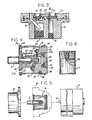
- Fig. 1 is a fragmentary longitudinal part sectional view of an axial piston pump embodying the invention;
- Fig. 2 is an end view taken from the left as viewed in Fig. 1;
- Fig. 3 is a fragmentary sectional view taken along the line 3-3 in Fig. 2;
- Fig. 4 is a sectional view on an enlarged scale of a detail, namely a cartridge with a retained rod;
- Fig. 5 is a partly diagrammatic view showing the manner in which a cartridge may be replaced;
- Fig. 6 is a part sectional view of a container and cartridge package that can be used in handling and shipping the cartridge.
- Referring to Figs. 1-3, the axial piston pump comprises a housing 10 that is adapted to be connected to an electric motor 11. Where the device is a motor, a comparable housing of a shaft will be provided.
- The housing 10 further includes a chamber or
cavity 13 and avalve block 12 closing the open end thereof and having inlet andoutlet ports shaft 14 connected to the motor 11 is journalled by abearing 15 which is supported by anannular end wall 17 of the housing 10. The shaft extends into thecavity 13 and has a spline connection with acylinder barrel 25.Such cylinder barrel 25 includes a plurality of axial cylinders 26 in which pistons 27 are mounted and have theirouter ends 27a formed with sphericalsurfaces engaging shoes 28 which are retained against an angular surface of a cam orswash plate 23 by aretainer 29. Aspring 30 supported on the shaft end face urges thecylinder barrel 25 against a valve surface 21a. Thevalve block 12 includes passages leading from theports cylinder barrel 25. The operation of the device as a pump or motor is well known and needs not be further described. - In accordance with the invention, a
cartridge 16 is interposed between thevalve block 12 and theend wall 17 of the housing 10 and includes thecylinder barrel 25 as a rotating group, anangle block 22 as a modification of the swash plate or cam and avalve plate 21 as a portion of thevalve block 12 and including the valve surface 21a having the arcuate openings 18a, 19a. - Referring to Fig. 4, the
cartridge 16 also comprises atubular casing 24 interconnecting thevalve plate 21 and theangle block 22. A removable plastic rod S is provided in thecartridge 16 to maintain the parts of the cylinder barrel in alignment before thecartridge 16 is used. - A
pin 31 extends radially from theangle block 22 through an axiallyelongated opening 32 in thecasing 24 so that there is limited permissible movement axially between thecasing 24 and theangle block 22 and anundulating spring 33 is interposed between thecasing 24 and aflange 34 on theangle block 22. An O-ring 35 is provided on a flange 36 of thevalve plate 21 and a further 0-ring 38 is provided in a groove 38 on the periphery of theangle block 22. Finally, thecartridge 16 includes aradial shaft seal 39 which is held in position in arecess 40 by asnap ring 41 to provide a seal for theshaft 14. - Referring to Fig. 1 an
annular sealing ring 42 in a groove in the end face of housing 10 provides a seal withvalve block 12. - When it is desired to replace the
cartridge 16, thevalve block 12 is removed by loosening and removingbolts 43 so that the cartridge subassembly can be removed and replaced by a new cartridge subassembly. - The
cartridge 16 is preferably handled and stored by placement in a container C filled with clean oil and closed by a suitable closure, the oil being of the type utilized in the hydraulic system. - The steps to be followed are as follows:
- 1. The
old cartridge 16 is removed from the housing 10. - 2. The
new cartridge 16 is removed from its sealed container C and inserted into the housing 10 (shaft seal 39 end first). - 3. Before the
angle block 22 bottoms in the housing 10, thecartridge 16 is rotated back and forth until ahole 47 in theangle block 22 engages a locatingpin 46 in the housing 10; and then thecartridge 16 is pressed in firmly. - 4. As the
cartridge 16 is inserted (step 3), the extended end of thedrive shaft 14 pushes the shipping rod S of the cartridge and engages thecylinder barrel 25. - 5. The
valve block 12 is attached by engaging locatingpin 45 in hole 44 of the valve plate, and then bolted to the housing 10. As thebolts 43 are tightened, thevalve block 12 presses against thevalve plate 21 which forces thebarrel 25 against thespring 30 bias onto theangle block 22. This ensures positive sealing of theangle block 22 against the housing 10. - 6. The hydraulic fittings are again mounted. The
case 24 is filled with clean oil which is provided in the cartridge container C. - 7. The unit is now ready to operate.
- Among the advantages offered by the construction are the following:
- 1. Economical design due to minimum of parts required.
- 2. Higher overall efficiency of operation because of common drive shaft, resulting in fewer bearings and no coupling shaft.
- 3. Lower replacement cost since the housing and . valve block are not routinely replaced.
- 4. All wear parts are replaced by exchange of the cartridge.
- 5. All seals are replaced by exchange of the cartridge.
- 6. Does not require special tools or technological training to service.
Claims (9)
Applications Claiming Priority (2)
| Application Number | Priority Date | Filing Date | Title |
|---|---|---|---|
| US06/630,074 US4611529A (en) | 1984-07-12 | 1984-07-12 | Axial piston machine constructed in a removable cartridge form to facilitate assembly and disassembly |
| US630074 | 2000-08-01 |
Publications (3)
| Publication Number | Publication Date |
|---|---|
| EP0168040A2 EP0168040A2 (en) | 1986-01-15 |
| EP0168040A3 EP0168040A3 (en) | 1987-01-21 |
| EP0168040B1 true EP0168040B1 (en) | 1989-05-17 |
Family
ID=24525646
Family Applications (1)
| Application Number | Title | Priority Date | Filing Date |
|---|---|---|---|
| EP85108556A Expired EP0168040B1 (en) | 1984-07-12 | 1985-07-10 | Axial piston pump or motor |
Country Status (4)
| Country | Link |
|---|---|
| US (1) | US4611529A (en) |
| EP (1) | EP0168040B1 (en) |
| JP (1) | JPH0678752B2 (en) |
| DE (1) | DE3570262D1 (en) |
Families Citing this family (21)
| Publication number | Priority date | Publication date | Assignee | Title |
|---|---|---|---|---|
| US4620475A (en) * | 1985-09-23 | 1986-11-04 | Sundstrand Corporation | Hydraulic displacement unit and method of assembly thereof |
| US4781527A (en) * | 1986-03-19 | 1988-11-01 | Sundstand Corporation | Cartridge pump |
| US4878346A (en) * | 1987-07-24 | 1989-11-07 | Hayes Industrial Brake, Inc. | Tab-aligned replaceable cartridge for master cylinder |
| JPH0733820B2 (en) * | 1988-09-12 | 1995-04-12 | 川崎重工業株式会社 | Swash plate type piston pump motor |
| JPH0612275Y2 (en) * | 1989-12-13 | 1994-03-30 | 株式会社神崎高級工機製作所 | Fixed swash plate for HST transmission |
| US5117633A (en) * | 1990-07-10 | 1992-06-02 | Allied-Signal Inc. | Pneumohydraulic actuator |
| US5494414A (en) * | 1994-12-02 | 1996-02-27 | Mi-T-M Corporation | Vertical shaft pressure washer coupling assembly |
| JPH09112410A (en) * | 1995-10-24 | 1997-05-02 | Mitsubishi Electric Corp | Swash plate pump |
| US5791882A (en) * | 1996-04-25 | 1998-08-11 | Shurflo Pump Manufacturing Co | High efficiency diaphragm pump |
| US6048183A (en) * | 1998-02-06 | 2000-04-11 | Shurflo Pump Manufacturing Co. | Diaphragm pump with modified valves |
| US6092998A (en) * | 1998-03-20 | 2000-07-25 | Devilbiss Air Power Company | Pump for a pressure washer |
| US6715994B2 (en) | 2001-11-12 | 2004-04-06 | Shurflo Pump Manufacturing Co., Inc. | Bilge pump |
| US6623245B2 (en) | 2001-11-26 | 2003-09-23 | Shurflo Pump Manufacturing Company, Inc. | Pump and pump control circuit apparatus and method |
| US7083392B2 (en) | 2001-11-26 | 2006-08-01 | Shurflo Pump Manufacturing Company, Inc. | Pump and pump control circuit apparatus and method |
| US6651794B2 (en) * | 2001-12-07 | 2003-11-25 | Caterpillar Inc | Hydro-mechanical combiner |
| ITRE20030032U1 (en) * | 2003-12-19 | 2005-06-20 | Annovi Reverberi Spa | PERFECT HYDRAULIC PUMP |
| ITRE20040015U1 (en) * | 2004-08-02 | 2004-11-02 | Annovi Reverberi Spa | BODY FOR DIFFERENT PISTON PUMP |
| DE102006058355A1 (en) * | 2006-03-10 | 2007-09-13 | Brueninghaus Hydromatik Gmbh | Combi pump housing for several nominal sizes |
| DE102011053659B4 (en) * | 2011-09-15 | 2021-12-23 | Linde Hydraulics Gmbh & Co. Kg | Hydrostatic axial piston machine with a rotatable leakage oil guide bushing that surrounds the engine assembly and is mounted in the housing |
| CN104625638B (en) * | 2014-12-30 | 2017-09-05 | 苏州萨伯工业设计有限公司 | Hydraulic pump driving shaft and its processing method |
| DE102018126395A1 (en) * | 2018-10-23 | 2020-04-23 | Moog Gmbh | Electrohydrostatic drive with an enlarged operating range |
Family Cites Families (11)
| Publication number | Priority date | Publication date | Assignee | Title |
|---|---|---|---|---|
| US2307719A (en) * | 1938-03-07 | 1943-01-05 | Jr John B Hawley | Hydraulic pump construction |
| US2776628A (en) * | 1952-07-10 | 1957-01-08 | Vickers Inc | Power transmission |
| US3274896A (en) * | 1963-10-07 | 1966-09-27 | Autolava Oy | Liquid pressure operated motor |
| US3457873A (en) * | 1967-03-20 | 1969-07-29 | Sperry Rand Corp | Pumping chamber decompression |
| US3481277A (en) * | 1967-09-28 | 1969-12-02 | Sperry Rand Corp | Power transmission |
| US3808949A (en) * | 1971-06-30 | 1974-05-07 | Deere & Co | Axial piston hydraulic motor |
| US3872562A (en) * | 1973-10-15 | 1975-03-25 | Fedders Corp | Method of compressor assembly |
| US4207804A (en) * | 1975-03-14 | 1980-06-17 | Kiyozumi Fukui | Crawler type vehicle driving apparatus |
| JPS5838632B2 (en) * | 1975-07-04 | 1983-08-24 | テイジンセイキ カブシキガイシヤ | exhaust motor |
| US4281971A (en) * | 1979-07-31 | 1981-08-04 | Abex Corporation | Inlet inducer-impeller for piston pump |
| US4357858A (en) * | 1980-02-15 | 1982-11-09 | Green Line, Inc. | Fluid actuated cylinder assembly |
-
1984
- 1984-07-12 US US06/630,074 patent/US4611529A/en not_active Expired - Lifetime
-
1985
- 1985-07-10 DE DE8585108556T patent/DE3570262D1/en not_active Expired
- 1985-07-10 EP EP85108556A patent/EP0168040B1/en not_active Expired
- 1985-07-12 JP JP60152619A patent/JPH0678752B2/en not_active Expired - Fee Related
Also Published As
| Publication number | Publication date |
|---|---|
| JPS6134362A (en) | 1986-02-18 |
| EP0168040A2 (en) | 1986-01-15 |
| JPH0678752B2 (en) | 1994-10-05 |
| EP0168040A3 (en) | 1987-01-21 |
| DE3570262D1 (en) | 1989-06-22 |
| US4611529A (en) | 1986-09-16 |
Similar Documents
| Publication | Publication Date | Title |
|---|---|---|
| EP0168040A2 (en) | Axial piston pump or motor | |
| US4381179A (en) | Pumps with floating wrist pins | |
| US3507584A (en) | Axial piston pump for nonlubricating fluids | |
| EP0607687B1 (en) | Multistage vacuum pump | |
| US4178133A (en) | Double-acting flexible tube pump | |
| CA2114321A1 (en) | Quick-Change Fluid Section for Piston-Type Paint Pumps | |
| EP0015127B1 (en) | Fluid motor-pump assembly | |
| EP2606261A1 (en) | Pump seal | |
| US5803169A (en) | Rotary stuffing box and seal assembly | |
| GB1594506A (en) | Piston pumps | |
| AU8516598A (en) | Hydraulic system and pump | |
| US5393205A (en) | Axial multi-piston compressor having rotary suction valve | |
| US4392787A (en) | Diaphragm pump | |
| SE509959C2 (en) | hydraulic Pump | |
| US5085127A (en) | Cavitation resistant hydraulic cylinder block porting faces | |
| US4632648A (en) | Grease pumps | |
| US5700140A (en) | Pump with improved bearing arrangement for axial position control | |
| EP1382845B1 (en) | Oil pump for marine steering gear | |
| EP0539188B1 (en) | Rotary vane device for hydraulic fluid | |
| JP2945651B2 (en) | Lubricating oil pump oil delivery mechanism | |
| AU8816598A (en) | Improvements to rotary pumps | |
| EP1053400B1 (en) | Hydraulic motor with lubrication path | |
| EP0661450A1 (en) | Rotary fluid pressure energy translating device with shaft seal | |
| AU605714B2 (en) | Folded channel radial pump | |
| RU2142575C1 (en) | Electric pump unit |
Legal Events
| Date | Code | Title | Description |
|---|---|---|---|
| PUAI | Public reference made under article 153(3) epc to a published international application that has entered the european phase |
Free format text: ORIGINAL CODE: 0009012 |
|
| AK | Designated contracting states |
Designated state(s): DE FR GB |
|
| PUAL | Search report despatched |
Free format text: ORIGINAL CODE: 0009013 |
|
| AK | Designated contracting states |
Kind code of ref document: A3 Designated state(s): DE FR GB |
|
| 17P | Request for examination filed |
Effective date: 19870304 |
|
| 17Q | First examination report despatched |
Effective date: 19870904 |
|
| GRAA | (expected) grant |
Free format text: ORIGINAL CODE: 0009210 |
|
| AK | Designated contracting states |
Kind code of ref document: B1 Designated state(s): DE FR GB |
|
| REF | Corresponds to: |
Ref document number: 3570262 Country of ref document: DE Date of ref document: 19890622 |
|
| ET | Fr: translation filed | ||
| PLBE | No opposition filed within time limit |
Free format text: ORIGINAL CODE: 0009261 |
|
| STAA | Information on the status of an ep patent application or granted ep patent |
Free format text: STATUS: NO OPPOSITION FILED WITHIN TIME LIMIT |
|
| 26N | No opposition filed | ||
| PGFP | Annual fee paid to national office [announced via postgrant information from national office to epo] |
Ref country code: FR Payment date: 19940613 Year of fee payment: 10 |
|
| PGFP | Annual fee paid to national office [announced via postgrant information from national office to epo] |
Ref country code: GB Payment date: 19940620 Year of fee payment: 10 |
|
| PGFP | Annual fee paid to national office [announced via postgrant information from national office to epo] |
Ref country code: DE Payment date: 19940623 Year of fee payment: 10 |
|
| PG25 | Lapsed in a contracting state [announced via postgrant information from national office to epo] |
Ref country code: GB Effective date: 19950710 |
|
| GBPC | Gb: european patent ceased through non-payment of renewal fee |
Effective date: 19950710 |
|
| PG25 | Lapsed in a contracting state [announced via postgrant information from national office to epo] |
Ref country code: DE Effective date: 19960402 |
|
| PG25 | Lapsed in a contracting state [announced via postgrant information from national office to epo] |
Ref country code: FR Effective date: 19960430 |
|
| REG | Reference to a national code |
Ref country code: FR Ref legal event code: ST |
|
| REG | Reference to a national code |
Ref country code: FR Ref legal event code: ST |
|
| REG | Reference to a national code |
Ref country code: FR Ref legal event code: ST |