EP0607687B1 - Multistage vacuum pump - Google Patents
Multistage vacuum pump Download PDFInfo
- Publication number
- EP0607687B1 EP0607687B1 EP93310242A EP93310242A EP0607687B1 EP 0607687 B1 EP0607687 B1 EP 0607687B1 EP 93310242 A EP93310242 A EP 93310242A EP 93310242 A EP93310242 A EP 93310242A EP 0607687 B1 EP0607687 B1 EP 0607687B1
- Authority
- EP
- European Patent Office
- Prior art keywords
- piston
- housing
- stage
- valve
- passage
- Prior art date
- Legal status (The legal status is an assumption and is not a legal conclusion. Google has not performed a legal analysis and makes no representation as to the accuracy of the status listed.)
- Expired - Lifetime
Links
- 238000005086 pumping Methods 0.000 claims description 73
- 238000004891 communication Methods 0.000 claims description 22
- 238000007789 sealing Methods 0.000 claims description 11
- XAGFODPZIPBFFR-UHFFFAOYSA-N aluminium Chemical compound [Al] XAGFODPZIPBFFR-UHFFFAOYSA-N 0.000 claims description 9
- 229910052782 aluminium Inorganic materials 0.000 claims description 9
- 230000008878 coupling Effects 0.000 claims description 4
- 238000010168 coupling process Methods 0.000 claims description 4
- 238000005859 coupling reaction Methods 0.000 claims description 4
- 238000005192 partition Methods 0.000 claims description 4
- 230000000295 complement effect Effects 0.000 claims description 2
- 239000004411 aluminium Substances 0.000 claims 1
- 238000005266 casting Methods 0.000 description 19
- 239000000463 material Substances 0.000 description 18
- 230000000712 assembly Effects 0.000 description 8
- 238000000429 assembly Methods 0.000 description 8
- 230000006835 compression Effects 0.000 description 6
- 238000007906 compression Methods 0.000 description 6
- 230000002459 sustained effect Effects 0.000 description 6
- 210000000707 wrist Anatomy 0.000 description 6
- 230000009471 action Effects 0.000 description 5
- 230000005540 biological transmission Effects 0.000 description 3
- 239000012530 fluid Substances 0.000 description 3
- 230000007246 mechanism Effects 0.000 description 3
- 229920001343 polytetrafluoroethylene Polymers 0.000 description 3
- 239000004810 polytetrafluoroethylene Substances 0.000 description 3
- 229910000906 Bronze Inorganic materials 0.000 description 2
- 230000008901 benefit Effects 0.000 description 2
- 239000010974 bronze Substances 0.000 description 2
- 150000001875 compounds Chemical class 0.000 description 2
- 238000010276 construction Methods 0.000 description 2
- KUNSUQLRTQLHQQ-UHFFFAOYSA-N copper tin Chemical compound [Cu].[Sn] KUNSUQLRTQLHQQ-UHFFFAOYSA-N 0.000 description 2
- 239000000945 filler Substances 0.000 description 2
- 238000004519 manufacturing process Methods 0.000 description 2
- 231100000331 toxic Toxicity 0.000 description 2
- 230000002588 toxic effect Effects 0.000 description 2
- 238000012546 transfer Methods 0.000 description 2
- 238000013459 approach Methods 0.000 description 1
- 238000001816 cooling Methods 0.000 description 1
- 238000013461 design Methods 0.000 description 1
- 239000002783 friction material Substances 0.000 description 1
- 239000010687 lubricating oil Substances 0.000 description 1
- 239000003921 oil Substances 0.000 description 1
- 231100000614 poison Toxicity 0.000 description 1
- -1 polytetrafluoroethylene Polymers 0.000 description 1
- 230000009467 reduction Effects 0.000 description 1
- 230000004044 response Effects 0.000 description 1
- 239000007787 solid Substances 0.000 description 1
- 229910001220 stainless steel Inorganic materials 0.000 description 1
- 239000010935 stainless steel Substances 0.000 description 1
- 239000000126 substance Substances 0.000 description 1
- 231100000701 toxic element Toxicity 0.000 description 1
- 239000003440 toxic substance Substances 0.000 description 1
- 238000003466 welding Methods 0.000 description 1
Images


Classifications
-
- F—MECHANICAL ENGINEERING; LIGHTING; HEATING; WEAPONS; BLASTING
- F04—POSITIVE - DISPLACEMENT MACHINES FOR LIQUIDS; PUMPS FOR LIQUIDS OR ELASTIC FLUIDS
- F04B—POSITIVE-DISPLACEMENT MACHINES FOR LIQUIDS; PUMPS
- F04B25/00—Multi-stage pumps
- F04B25/02—Multi-stage pumps of stepped piston type
-
- F—MECHANICAL ENGINEERING; LIGHTING; HEATING; WEAPONS; BLASTING
- F04—POSITIVE - DISPLACEMENT MACHINES FOR LIQUIDS; PUMPS FOR LIQUIDS OR ELASTIC FLUIDS
- F04B—POSITIVE-DISPLACEMENT MACHINES FOR LIQUIDS; PUMPS
- F04B37/00—Pumps having pertinent characteristics not provided for in, or of interest apart from, groups F04B25/00 - F04B35/00
- F04B37/10—Pumps having pertinent characteristics not provided for in, or of interest apart from, groups F04B25/00 - F04B35/00 for special use
- F04B37/14—Pumps having pertinent characteristics not provided for in, or of interest apart from, groups F04B25/00 - F04B35/00 for special use to obtain high vacuum
- F04B37/16—Means for nullifying unswept space
-
- F—MECHANICAL ENGINEERING; LIGHTING; HEATING; WEAPONS; BLASTING
- F04—POSITIVE - DISPLACEMENT MACHINES FOR LIQUIDS; PUMPS FOR LIQUIDS OR ELASTIC FLUIDS
- F04B—POSITIVE-DISPLACEMENT MACHINES FOR LIQUIDS; PUMPS
- F04B41/00—Pumping installations or systems specially adapted for elastic fluids
- F04B41/06—Combinations of two or more pumps
-
- F—MECHANICAL ENGINEERING; LIGHTING; HEATING; WEAPONS; BLASTING
- F04—POSITIVE - DISPLACEMENT MACHINES FOR LIQUIDS; PUMPS FOR LIQUIDS OR ELASTIC FLUIDS
- F04B—POSITIVE-DISPLACEMENT MACHINES FOR LIQUIDS; PUMPS
- F04B49/00—Control, e.g. of pump delivery, or pump pressure of, or safety measures for, machines, pumps, or pumping installations, not otherwise provided for, or of interest apart from, groups F04B1/00 - F04B47/00
- F04B49/007—Installations or systems with two or more pumps or pump cylinders, wherein the flow-path through the stages can be changed, e.g. from series to parallel
-
- F—MECHANICAL ENGINEERING; LIGHTING; HEATING; WEAPONS; BLASTING
- F04—POSITIVE - DISPLACEMENT MACHINES FOR LIQUIDS; PUMPS FOR LIQUIDS OR ELASTIC FLUIDS
- F04B—POSITIVE-DISPLACEMENT MACHINES FOR LIQUIDS; PUMPS
- F04B53/00—Component parts, details or accessories not provided for in, or of interest apart from, groups F04B1/00 - F04B23/00 or F04B39/00 - F04B47/00
- F04B53/10—Valves; Arrangement of valves
- F04B53/102—Disc valves
- F04B53/1022—Disc valves having means for guiding the closure member axially
Definitions
- the present invention is directed to a multistage vacuum pump and more specifically to a multistage vacuum pump comprised of a single piston cylinder assembly having an enlarged diameter central portion with one end of the assembly and opposite sides of the enlarged diameter central portion providing three stages interconnected by passage means.
- the U.S. Patent 4,560,327 to BEZ et al. discloses a porting and ducting arrangement for a pair of adjacent cylinders of a multistage vacuum pump wherein a plurality of passages extend longitudinally in the walls of the cylinders and communicate with the interiors of the cylinders through respective ports.
- a plurality of recesses in the form of arcuate depressions may be located in the ends of the cylinder walls or in the bottom surface of the cylinder head which register with respective passages or groups of passages and suitable openings are provided in the cylinder head in communication with the recesses for supplying or exhausting fluid to or from the interiors of the cylinders.
- U.S. Patent 4,790,726 in the name of Balkau et al. and assigned to the same Assignee as the present application, is also directed to a reciprocatory piston and cylinder machine adapted to be used as an oil-free vacuum pump.
- the vacuum pump disclosed in this application is directed to a cylinder having a first portion closed at one end and a second portion contiguous with, but of smaller diameter than, the first portion and a piston having a cylinder head portion slidable in the first cylinder portion and a second cylindrical piston portion slidable in the second cylinder portion with said piston head portion having a front face facing the closed cylinder end and an annular back face.
- a gas inlet is provided for introducing gas to the interior of the first cylinder portion between the front face of the piston head portion and the closed cylinder end on reciprocation of the piston.
- a first exhaust port is provided for exhausting gas from the interior of the first cylinder portion ahead of the piston head portion by pumping action of the front face of the piston head portion, a one-way valve is provided in the first exhaust port which is operable to permit the exhaust of gas from the interior of the first cylinder portion ahead of the piston head portion and a second exhaust port is provided for the exhaust of gas from the interior of the first cylinder portion behind the piston head portion by the pumping action of the back face of the piston head portion.
- Sealing means are provided for the piston head portion which includes a sleeve of low friction material disposed on the cylindrical surface of the piston such that over the temperature range encountered during the normal operation of the pump, a mean gap is sustained between the sleeve and the cylinder, which gap is of a maximum size at which leakage of gas past the sleeve is at a level for an acceptable degree of vacuum to be sustained by the pump.
- a similar sleeve is provided on the second piston portion and resilient means are provided adjacent the end of the sleeve remote from the first piston portion for forcing the sleeve into sliding engagement with the wall of the cylinder.
- the one way valve in the exhaust port is provided with projecting means which are adapted to be engaged by the piston for opening the valve in the exhaust port controlled thereby on each stroke of the piston even though the pressure within the cylinder is too low to open the valve against the force of the spring biasing the valve into normally closed position.
- U.S. Patent 4,854,825 to BEZ et al. discloses an oil-free, multistage vacuum pump having the cylinders, crankcase and passage means formed in a single casting with two pairs of cylinders opposed to each other in a substantially common plane on opposite sides of the axis of crankshaft support means extending perpendicular to the axes of the cylinders.
- Each cylinder is provided with a large diameter portion adjacent the cylinder head and a smaller diameter portion adjacent the axis of the crankshaft.
- a step piston is reciprocally mounted in each sleeve and is operatively connected to a crankshaft for rotation in the crankcase.
- One pair of piston cylinder assemblies are considered the high pressure pumping assemblies while the other pair of pistons and cylinder assemblies are considered to be the low pressure pumping assemblies. While such a vacuum pump is capable of providing extremely low pressures, the need for the four piston and cylinder assemblies makes the size and weight of the pump much too great and the noise level is too high. Furthermore, such a multistage vacuum pump is very complicated in construction and it requires too many parts and is far too expensive.
- the present invention which is defined in claims 1 to 12, provides a new and improved oil-free, multistage vacuum pump which eliminates the various shortcomings of the aforementioned pumps.
- the present invention provides a new and improved oil-free, multistage vacuum pump which utilizes only a single piston and cylinder assembly having an enlarged diameter central portion with an end portion and opposite side portions of the enlarged diameter portion providing three compression stages which can be connected in at least three different ways to provide different modes of operation.
- the present invention provides a new and improved oil-free, multistage vacuum pump having a single piston and cylinder assembly with the cylinder and inlet passages for each stage being formed within the castings forming the housing of the pump.
- the present invention provides a new and improved oil-free, multistage vacuum pump having a single piston and cylinder assembly with valving means including a spring biased valve assembly and an electromagnetic or mechanical valve assembly with a smaller opening than the spring biased valve assembly disposed in parallel at an outlet of a first stage and at least one valve assembly disposed at an outlet of second and third stages respectively which may be either spring biased valve assemblies or electromagnetic valve assemblies.
- the present invention provides a new and improved oil-free, multistage vacuum pump comprising a drive unit having a motor driven crankshaft in a cast aluminum housing and at least one pumping unit having a single multistage piston and cylinder assembly operatively connected to the crankshaft wherein the housing of the drive unit is provided with sealing means and a one-way valve connected to one stage of said pumping unit to maintain said housing of the drive unit at sub-atmospheric pressure and wherein said drive unit is provided with means for connecting additional pumping units and with integral internal passage means formed within the housing of the drive unit for interconnecting multiple pumping units.
- the present invention provides a new and improved oil-free, multistage vacuum pump wherein at least two pumping units are connected to a common drive means with the two pumping units connected in parallel or in series to provide different pumping capacities.
- the present invention provides a new and improved oil-free, multistage vacuum pump having a single piston and cylinder assembly with valving means wherein each of the valving means for controlling the various stages of the pump are in the form of self-contained cylindrical cartridges which may be inserted in the end faces of the housing parts prior to interconnection to facilitate assembly of the pump and to replacement of the individual valve assemblies.
- Figure 1 is a schematic plan view of a drive unit having two pumping units connected thereto with each pumping unit being an oil-free multistage vacuum pump having a single piston and cylinder assembly.
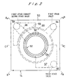
- Figure 2 is an end elevation view of a pumping unit.
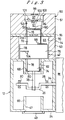
- Figure 3 is a sectional view of the pumping unit taken along the line C-C of Figure 2 with the piston disposed in the bottom dead center position.
- Figure 4 is a sectional view similar to Figure 3 with the piston in the top dead center position.
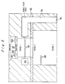
- FIG 5 is a sectional view of the pumping unit taken along the line B-B of Figure 2 with the piston removed.
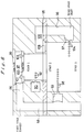
- Figure 6 is a sectional view of the pumping unit taken along the line A-A- in Figure 2.
- Figure 7 is a top plan view of the drive unit with the cover plate removed.
- Figure 8 is a side elevational view of the cover plate for the drive unit.
- Figure 9 is an end elevational view of the drive unit with the pumping unit removed.
- Figure 10 is a schematic view of a piston and the fluid flow paths between the three stages with the three stages connected in series.
- Figure 11 is a schematic view of a piston and the flow paths between the stages with stages 1 and 2 connected in parallel and stage 3 connected in series with stages 1 and 2.
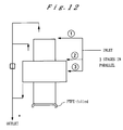
- Figure 12 is a schematic view of a piston and flow path connecting the three stages with the three stages connected in parallel.
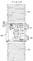
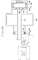
- Figure 13 is a sectional view of a further embodiment of the present invention with two pumping units connected to a common drive unit and incorporating cartridge valves.
- Figure 14 is an end view of the assembly shown in Figure 13 as viewed from the left with a portion of the drive unit housing removed.
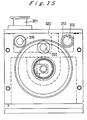
- Figure 15 is a sectional view taken along the line 15-15 of Figure 13.
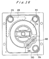
- Figure 16 is a sectional view taken along the line 16-16 of Figure 13.
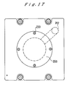
- Figure 17 is an end view taken along the line 17-17 in Figure 13.
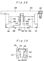
- Figure 18 is an enlarged sectional view of the first stage outlet valve cartridge.
- Figure 19 is an enlarged sectional view of a valve cartridge as used in other locations.
- Figure 20 is an enlarged sectional view of the piston assembly for a pump unit.
- the vacuum pump 10 shown schematically in Figure 1 is comprised of a drive unit 12 and two pumping units 14 and 16 mounted on opposite sides of the drive unit 12.
- the drive unit or drive module 12 includes a housing 18 supporting an electric motor 20 having an output shaft 22.
- the housing 18 is secured to a transmission housing 24 to which the two pumping units or pumping modules 14 and 16 are secured.
- a crankshaft 26 is rotatably mounted within the housing 24 on bearings 28 and 30.
- the crankshaft 26 extends through the end wall 32 of the housing and is hermetically sealed relative to the housing 24 by means of a sealing member 34 of any suitable design.
- the output shaft 22 of the motor 20 is connected to the crankshaft 26 by means of a coupling 36.
- the transmission housing 24 is of cast aluminum material and includes a pair of integral passages shown schematically at 46 and 48 which provide inlet and outlet passages respectively for the respective pumping modules 14 and 16. Suitable inlet and outlet fittings (not shown) would be connected to the passages 46 and 48 respectively for connection to the device to be evacuated and the atmosphere or a suitable receptacle in the event toxic gasses are involved. Such fittings would extend through the cover or a wall of the transmission housing 12 in fluid communication with the respective passages 46 and 48.
- Each of the pumping units 14 and 16 is an oil-free, multistage vacuum pump and since the pumping units are identical, a detailed description will be provided with respect to the pumping module 14.
- the pumping module 14, as shown in Figures 2-6, is attached to the drive unit 12 by any suitable means (not shown) and is comprised of a cast aluminum housing 50 having a variable diameter cylinder 52 and three passages 54, 56 and 58 integrally formed therein in parallel with each other and the cylinder during the casting process.
- the cylinder and inlet passages extend through the housing 50 relative to each other as best seen in Figures 2, 5 and 6.
- the cylinder 52 is provided with two end portions 60 and 62 of approximately equal diameter with the end portion 62 being located in a cylindrical portion 68 of the housing 24 of the drive unit.
- the cylindrical portion 68 extends into the housing 24 of the drive unit 12 as seen in Figure 3.
- a similar cylindrical portion 69 is formed in the opposite wall of the housing 24 which will form a part of the cylinder of a second pumping unit, such as the pumping unit 16 which is shown in Figure 2 as being on the opposite side of the drive unit 12 from the pumping unit 14. Since the interior of the drive unit 12 must be maintained at sub-atmospheric pressure, a suitable cover 49 may be secured over the opening 47 in order to provide a hermetically sealed closure.
- the cylinder 52 is also provided with a central larger diameter portion 70 intermediate the two smaller diameter portions 60 and 62.
- the pumping unit 14 includes a hollow piston 42 which is provided with two approximately equal diameter end portions 72 and 74 and an enlarged diameter middle portion 76.
- the piston is covered on all cylindrical surfaces with a low-wear material 78 having a low coefficient of friction. The material is applied in such a manner as to not cause any mechanical interference with the cylinder walls when the piston expands.
- the covering material 78, the piston 42 and cylinder housing 50 each have the same co-efficient of expansion.
- the piston 42 and the cylinder housing 50 may be formed of aluminum or other material such as stainless steel which may be used for the piston.
- the covering material 78 may be substantially identical to that disclosed in the Balkau et al.
- a cup-shaped contact seal 80 of similar material is secured to the end of the smaller diameter portion 74 to prevent the entry of higher pressure gasses in the interior of the drive unit 12 from entering into the working space of the pump.
- the cylinder housing 50 is comprised of two separate castings 51 and 53 and an intermediate valve plate 55. The three components of the housing 50 are secured to each other by any suitable means (not shown).
- the main inlet passage 54 for the pump extends through the cylinder housing 50 as best seen in Figures 2 and 5.
- the end 84 of the inlet passage 54 is disposed in alignment with the inlet passage 115 extending through the end wall of the drive unit 12 as shown in Figure 7 which in turn is connected to an inlet adapted to be connected to the object being evacuated as will be described hereinafter.
- the upper end of the inlet passage 54 as viewed in Figure 5, is connected to a passage 90 which extends approximately 270° about the end portion 60 of the cylinder 52 as best seen in Figure 2.
- the circumferential passage 90 communicates with the interior of the portion 60 of the cylinder 52 through a plurality of radial passages 92 which extend in a circumferential line located immediately above the top end 94 of the piston 42 when the piston 42 is located at the bottom dead center position as illustrated in Figure 3.
- a valve plate 100 is secured to the top end of the cylinder 52 as shown in Figure 3 by any suitable means (not shown).
- the volume 61 between the valve plate 100 and the upper end 94 of the piston 42 defines stage 1 of the multistage pump.
- the valve plate 100 is provided with a pair of valves 101 and 103 which allow the passage of gas from the cylinder upon upward movement of the piston 42.
- the valve 101 may be an electromagnetically controlled valve while the valve 103 is a spring-biased one-way valve.
- An outlet chamber 97 is defined between a cover plate 99 which is hermetically connected to the housing 50 and the valve plate 100.
- the chamber 97 communicates with the passage 58 in the housing 50 through a lateral passage 96.
- the passage 58 which is best seen in Figures 2 and 6, constitutes a first stage exhaust passage and a second stage inlet passage.
- the passage 58 together with the lateral passage 96, should have a volume which is approximately equivalent to the volume displaced from stage 1 to minimize pressure build-up in the passage 58.
- the passage 58 is also connected to a high pressure outlet via the one way valve 102 located in the drive unit as shown in Figure 7.
- the passage 58 communicates with the large diameter portion 70 of the cylinder through a plurality of apertures 98 by means of a substantially arcuate passage 59 which is best seen in Figures 2 and 6.
- the apertures 98 are disposed in a circumferential line which is exposed by the enlarged diameter portion 76 of the piston 42 which the piston is at its bottom dead-center position as shown in Figure 3.
- the annular space 63 above the enlarged diameter portion 76 of the piston 42 defines stage 2 of the multi-stage pump.
- the apertures 98 Upon movement of the piston 42 from the bottom dead-center position toward the top dead-center position, the apertures 98 will be closed and the gasses in stage 2 will be forced outwardly through a one-way valve 108 located in the valve plate 55 which is secured between the housing portions 51 and 53.
- the gasses Upon passing through the spring-biased one-way valve 108, the gasses enter a lateral passage 109 which intersects with the passage 56 which extends parallel to the cylinder 52.
- the lower end of the passage communicates with a lateral passage 57 which extends about substantially 90° of the circumference of the cylinder 52 as best seen in Figures 2 and 6.
- the lateral passage 57 communicates with the interior of the enlarged diameter portion 70 of the cylinder 52 through a plurality of radially extending passages 104 which are disposed in a circumferential line and which are exposed when the piston 42 reaches the top dead-center position as shown in Figure 4.
- the gasses expelled from stage 2 will enter stage 3 of the multi-stage pump which is defined by the space 65 between the enlarged diameter portion 76 of the piston 42 and the end wall of the housing 24 of the drive unit 12.
- the gasses in stage 3 Upon movement of the piston 42 from the top dead-center position to the bottom dead-center position, the gasses in stage 3 will be expelled through the passage 113 controlled by the spring-biased one-way valve 110 mounted within the drive unit 12 as shown in Figure 7.
- the pumping action achieved by the three stages of the multi-stage pump substantially reduces the pressure in a vessel which has been connected to the inlet 126 of the drive unit 12.
- the drive unit 12 which is normally disposed in the position shown in Figure 9, is provided with a transverse partition 150 which defines a lower chamber 152 in which the drive mechanism is located which interconnects the motor 20 to the piston 42.
- the passage 116 shown in the end wall 154 of the drive unit 12, is also shown in Figure 4 and is controlled by the spring-biased one-way valve 114.
- the crankshaft 26 extends through a side wall 32 of the drive unit and is hermetically sealed relative thereto by the seal 34.
- the upper portion of the housing 24 of the drive unit 12 is divided into three separate chambers 140, 142 and 144 by means of partitions 143 and 145 as best seen in Figure 7.
- the drive unit 12 is provided with a cover 120 shown in Figure 8 which is adapted to be hermetically sealed to the top of the housing 24 by means of the seals 122 extending about the entire periphery of the cover. Similar seals can be provided for engagement with the upper surfaces of the partitions 143 and 145.
- the three chambers 140, 142 and 144 will be hermetically sealed relative to each other when the cover 120 is secured to the housing 24 by any suitable means (not shown).
- a fitting 124 is secured to the upper surface of the cover 120 to provide a connection to whatever device is to be evacuated by means of the multi-stage vacuum pump.
- the inlet passage 126 extends through the fitting 124 and the cover 120 into communication with the Z-shaped passage 140 as shown in Figure 7 which in turn is provided with the passage 115 which is disposed in communication with the inlet passage 54 in the housing 50 of the pumping unit 14 whereby the gasses can pass to stage 1.
- the third stage exhaust passage 113 in the housing 24 of the drive unit is in communication with the exhaust passage 112 leading from stage 3 and is also in communication with the chamber 142 controlled by the spring-biased one-way valve 110.
- the chamber 142 is an exhaust chamber and is connected through the passages 136, 132 and 130 to the atmosphere as shown in Figures 7 and 8.
- the chamber 144 would also act as an exhaust chamber and the gasses therein would be exhausted through the atmosphere through the passages 134, 132 and 130. Also, a second inlet would be provided for the chamber 140 and passages equivalent to the passages 111, 113 and 115 would be formed in the end walls adjacent the cylindrical projections 69.
- the vessel to be evacuated is connected to the fitting 124 on the cover 120 of the drive unit and gas will pass through the passage 126, the chamber 140 and the passage 115 into the inlet passage 54 in the drive unit 14.
- the gas will then enter the compression space of stage 1 via the holes 92 disposed around the circumference of the cylinder wall when the piston is near bottom dead-center.
- the gas which has entered the compression space of stage 1 will reach a higher pressure and will be expelled through either the electromagnetically operated valve 101 or the spring-biased one-way valve 103.
- the gas is now transferred via the chamber 97, the passage 96 and the passage 58 to stage 2 through the passage 59 and the holes 98 which are uncovered when the piston 42 is at the bottom dead center position.
- the gas in stage 2 is expelled via the one-way valve 108, through the passages 109, 56 and 57 and enters stage 3 through the ports 104 which are uncovered as the piston approaches the top dead-center position as shown in Figure 4.
- the gas in stage 3 is expelled through the one-way valve 110 into the chamber 142 of the drive unit 12 from which it will then exhaust to the atmosphere.
- the gas could be collected in a separate vessel in situations where the gas is of a toxic nature.
- any gas leaking past the contact seal 80 at the lower end of the piston 42 will also enter stage 3 and be expelled in the same manner.
- the pressure in chamber 152 of the drive unit 12 will be reduced when the piston moves from the bottom dead-center position to the top dead-center position at which time the pressure in stage 3 will be substantially reduced allowing the one-way valve 114 to open.
- the one-way valve 114 permits gas to enter stage 3 to lower the pressure in the drive unit to about 1/10 of an atmosphere. It is important to make sure that the pressure in the drive unit is not so low as to prevent heat transfer from the internal mechanism of the drive unit and the pumping unit via the gas (convection) to the walls or surfaces of the housing which are of aluminum.
- the electromagnetic valve 101 which controls the exhaust of gasses from stage 1 is normally spring-biased to a closed position and is located in a relatively small opening having a diameter of approximately 1/16 of an inch.
- the spring-biased one-way valve 103 is located in an opening approximately 100 times the area of the opening of the electromagnetic valve.
- the spring-biased valve will operate to allow the high pressure gasses from stage 1 to flow to the passage 58 and from there to the exhaust chamber 142 in the drive unit 12 through the high pressure valve 102 and to the second stage.
- the electromagnetic valve is used to guarantee the opening of the passage between the first and second stages.
- the electromagnetic valve is phased to open before the piston reaches the top dead center and closed before descent of the piston.
- the outlet passages from the second and third stages can be controlled by either a spring-biased valve as shown, which is normally closed or a combination of valves similar to that described above with respect to the first stage outlet.
- the sliding velocity (V) of the piston should be limited to below 300 feet/minute (1.5m/sec).
- the pumping speed of one complete pumping unit should be 100 l/min with the ultimate pressure of 20mTorr. In practice, this means that the ultimate pressure should be much less than 20mTorr when new to allow for wear.
- the motor in the drive unit should be capable of 1800 rpm which is a commonly available speed.
- the stroke of the piston should be at least 25.4mm to obtain good compression in the high vacuum stage.
- the mass of the piston and associated mechanical parts is kept to an absolute minimum because of considerations of vibration, noise and energy. It is therefore important to make the piston as small as possible while preventing undue increases in rotational velocity.
- Stages 1, 2 and 3 can all be connected in series as shown in Figures 2-6 of the present application and as shown schematically in Figure 10. Stages 1 and 2 can also be connected in parallel and stage 3 can be connected in series with stages 1 and 2 as shown schematically in Figure 11 or stages 1, 2 and 3 can all be connected in parallel as shown schematically in Figure 12.
- the different connections of the stages can readily be accomplished during the manufacture of the pumping unit by varying the location and connection of the passages in the pumping unit.
- stages 1 and 2 When stages 1 and 2 are connected in parallel with each other and in series with stage 3, it is possible to operate the multi-stage pump as a medium pumping speed and medium ultimate pressure pump. When the stages are all connected in series, the pump can operate at a low pumping speed with very good ultimate pressure. When the three stages are connected in parallel, it is possible to operate the pump at a high pumping speed and at a higher pressure.
- the multi-pump assembly shown in Figure 13 includes a drive unit 200 having a first pump unit 202 and a second pump unit 204 mounted on opposite sides thereof.
- a motor unit 206 is detachably connected to one side of the drive unit 200 and includes an electric motor M having an output shaft 208 coupled to a crankshaft 210 by means of a coupling unit 212 secured to the two shafts by splines 214 and 216, respectively.
- the crankshaft 210 is rotatably mounted in the drive unit 200 by means of bearings 218 and 220.
- the crankshaft 220 is provided with two crank pins 222 and 224 which are 180° out of phase with each other.
- the pump units 202 and 204 are identical to each other and are similar in some aspects to the pump unit 14 shown in the first embodiment.
- the pump unit 202 is comprised of two main castings 226 and 228 having circumferentially extending fins thereon for cooling purposes.
- the castings may be of aluminum or any other suitable material.
- the casting 226 is provided with a stepped cylindrical bore having a first smaller diameter cylindrical portion 230 in which the piston will reciprocate and a second larger diameter cylindrical portion 232 adapted to receive a valve cartridge 234 which will be described in detail hereinafter.
- the second casting 228 is provided with a cylindrical bore 236 having a larger diameter than the bore 230 in the casting 226.
- the casting 238, which forms the housing for the drive unit 200, is also provided with a cylindrical bore 240 having a diameter substantially equal to the diameter of the bore 230 in the first casting 226.
- the three cylindrical bores 230, 236 and 240 provide a stepped cylinder similar to the stepped cylinder in the first embodiment for receiving a complementary stepped piston 242 therein.
- the two casting portions 226 and 228 are connected to each other by suitable means with a sealing ring 242 therebetween and the casting 228 is in turn connected to the housing 238 of the drive unit 200 by any suitable means such as bolts or the like with a sealing ring 248 disposed therebetween.
- the piston 242 may be a hollow piston similar to the previous embodiment which is provided with two substantially equal diameter end portions 250 and 252 and an enlarged diameter middle portion 254. As in the previous embodiment, the piston is covered on all cylindrical surfaces with a low-wear material having a low coefficient of friction. The material is applied in such a manner as to not cause any mechanical interference with the cylinder walls when the piston expands. The covering material, the piston and the cylinder housing all have the same coefficient.
- the piston 242 and the castings 226, 228 and 238 may be formed of aluminum or other materials.
- the covering material 78 may be substantially identical to that disclosed in the Balkau et al.
- the lower end of the piston which is slidably disposed within the cylindrical portion 240 of the drive unit 200 is provided with a cup-shaped contact seal 256 which is biased outwardly into engagement with the cylindrical surface 240 by means of a suitably dimensioned O-ring 258.
- the cup-shaped contact seal 256 is secured onto the lower end of the piston 252 by means of a threaded sleeve 260 having a lower flange 262.
- the upper end of the piston 250 is provided with a transverse bore 264 having a hollow tubular wrist pin 266 secured therein by means of a force fit.
- the pair of stepped plug members 268 having an O-ring 270 disposed in the reduced diameter central portion thereof are secured in recesses in the upper end of the piston 250 at opposite ends of the wrist pin 266 by means of a force fit.
- the piston 242 is connected to the crankshaft 210 by means of a hollow tubular piston rod 272 which is connected to the crank pin 224 by means of an offset connector 274 and an interposed bearing 276.
- the piston rod 272 for the pump unit 202 will be in substantial alignment with the piston rod for the pump unit 204 which in turn will be connected to the crank pin 222 by means of a similar offset connector 278 and interposed bearing 280.
- Such an arrangement will provide improved balancing of the assembly to reduce vibrations.
- a short hollow tubular sleeve 282 is transversely secured to the upper end of the piston rod 272.
- the sleeve 282 may be integrally cast with the piston rod 272 or may be separately formed and secured thereto by any suitable means such as welding or the like, depending upon the materials involved.
- a bearing sleeve 284 is disposed between the sleeve 282 and the wrist pin 266 to provide a pivotal connection between the piston rod 272 and the wrist pin 266 which is fixedly connected to the upper end of the piston 250.
- a suitable recess 286 is provided in the upper end of the piston 250 to accommodate the pivotal connection.
- the hollow interior of the wrist pin 266 is disposed in communication with the hollow interior of the piston rod 272 as shown schematically by dashed lines 288.
- the cartridge valve 234 acts as the outlet valve for stage one which is the same as stage one in the first embodiment.
- an electromagnetic valve 101 and a spring biased one-way valve 103 were provided in a valve plate 100 which defined stage one.
- the cartridge 234 replaces the valve plate, the cover plate and the two valves of the first embodiment.
- the cartridge valve 234 is fitted into the cylindrical bore 232 as shown in Figure 13 and secured therein by means of a plurality of bolts 233, one of which is shown in Figure 13.
- Figure 18 shows the cartridge valve in greater detail.
- the cartridge valve includes a hollow cylindrical portion 290 with a plurality of apertures 292 extending therethrough.
- An end plate 294 is integral with the cylindrical portion 290 and is provided with a bevelled valve seat 296.
- a mounting plate 298 is also integrally formed with the cylindrical portion 290 and is provided with laterally extending flanges having apertures for receiving the mounting bolts 233.
- a hollow cylindrical flange 300 extends downwardly from the center portion of the mounting plate 298 and the stem 302 of the valve 304 is slidably mounted in the sleeve 300 by means of splines 305.
- the valve 304 has the entire lower surface covered with a vinyl-rubber compound 306 and a plurality of projections or a circular protuberance 308 is provided on the lower surface thereof for engagement of the end of the piston 250 for opening the valve when the pressure in stage one is insufficient to overcome the force of the spring 310 which normally biases the valve 304 into engagement with the valve seat 296.
- a pair of O-rings 312 are provided for sealing the cartridge valve in the bore of the casting 226. Such a cartridge may be pre-assembled to facilitate the final assembly of the pump and to also facilitate a replacement of the valve at any time during the life of the pump.
- each pump of the embodiment shown in Figure 13 is provided with three stages in the exact same location as the three stages in the first embodiment.
- the inlet and outlet and the connections between the stages are substantially identical to those disclosed with respect to the first embodiment.
- the principle difference resides in the type of valve used to control the various stages.
- the cartridge valve 234 is used to control the outlet for the first stage.
- the inlet to the first stage is substantially identical to the inlet 54, 90 and 92 shown in Figure 5 of the first embodiment.
- a continuous slit (not shown) could be utilized since the use of a slit would be easier to manufacture than the holes 92.
- the inlet passage 312 shown in Figures 15, 16 and 17 which are sectional views of the second embodiment, is equivalent to the passage 54 shown in Figure 5.
- the inlet passage 312 communicates with the circumferentially extending passage 314 which is equivalent to the passage 90 in Figure 5.
- the passage 316 shown in Figures 15 and 16 constitutes the first stage exhaust which also communicates with the second stage inlet 318.
- the first stage exhaust passage 316 and the second stage inlet passage 318 are substantially identical to the first stage exhaust passage 58 and second stage inlet passage 59 of the first embodiment shown in Figure 2 and Figure 6 of the first embodiment.
- the second stage inlet 318 will communicate with the second stage by means of a slit (not shown) or a plurality of apertures such as shown at 98 in Figure 6.
- the first stage outlet passage 316 communicates with an outlet chamber 320 in the drive unit 200 which is similar to the outlet chamber 142 shown in Figure 7 of the first embodiment.
- the passage 322 which constitutes the third stage exhaust also communicates with the exhaust chamber 320 as shown in Figure 15.
- the passage 324 shown in Figure 16 is equivalent to the passage 56 which connects the second stage outlet to the third stage inlet as shown in Figure 6 of the first embodiment.
- two identical exhaust valves 326 and 328 are provided for the second stage in lieu of the single valve 108 shown in Figure 6 of the first embodiment.
- the two valves 326 and 328 communicate with the passage 324 through a chamber 330 equivalent to the passage 109 shown in Figure 6.
- the opposite end of the passage 56 is connected to inlet holes or a slit in stage three equivalent to the holes 104 shown in stage three in Figure 6 of the first embodiment.
- a passage having substantially the same configuration of the passage 330 but located in direct alignment therewith in Figure 16, is provided for connecting the lower end of the passage 324 with the holes of the third stage.
- the new valves 326 and 328 are drop-in cartridge valves similar to the cartridge valves 234 shown in Figure 18.
- the cartridge valve 326 is shown in detail in Figure 19 and is comprised of a cylindrical body 332 having an end wall with an aperture 334 therein.
- the valve 336 is coated with a vinyl-rubber compound and the valve stem 338 is slidably connected to a closure plate 340 by means of a spline connector 342.
- the valve 336 and the end plate 340 may be inserted into the cylindrical housing 332 and a circlip 344 secures the assembly within the cylindrical housing.
- a coil spring 346 is provided between the valve 336 and the plate 340 to normally bias the valve 336 into engagement with a valve seat surrounding the aperture 334.
- One of the second stage exhaust valves 326 is shown in Figure 13 whereby it is seen that the valves 326 and 328 can readily be dropped into apertures in the casting 326 prior to connecting the castings 226 and 228 together.
- the third stage exhaust valve 350 shown in Figure 13 is also a drop-in cartridge type valve similar to the valves 326 and 328 and can readily be dropped into a suitable aperture in the casting 238 of the drive unit prior to connection of the pump unit 202 to the drive unit 200.
- a valve substantially identical to the valve 350 is also provided at the end of the first stage exhaust passage 316 where it enters into the exhaust chamber 320 in the drive unit.
- the exhaust chamber 320 is provided with an outlet fitting 321 shown in Figure 15 which may be connected to any suitable type of container for collecting the exhaust gasses from the first and third stages in the event toxic elements might be included in the exhaust gasses.
- the inlet passage 312 as shown in Figure 15 communicates with an inlet chamber 313 formed in the housing 238 of the drive unit 200.
- This inlet chamber 313 is equivalent to the inlet chamber 140 shown in Figure 7 of the first embodiment.
- An inlet fitting 323 identical to the outlet fitting 322 is provided on the housing 238 and communicates with the inlet chamber 313 in a manner not shown in the drawings.
- the inlet fitting is adapted to be connected to whatever vessel is to be evacuated.
- the third stage of the pump unit 202 is connected to the interior of the housing 238 of the drive unit 200 by means of a one way valve 360 which is normally spring biased into the closed position as shown in Figure 14.
- a plate 362 is secured to the end of the valve stem 364 by means of a screw 366 and a spring 368 extending between the housing 238 and the plate 362 biases the valve 360 into engagement with the seat formed on the housing 238.
- the valve 360 is equivalent to the valve 114 disclosed in Figure 4 of the first embodiment and is provided to permit gas to enter stage three to lower the pressure in the drive unit to about 1/10 of an atmosphere.
- the housing 238 of the drive unit 200 is maintained in a sealed condition by the seal 370 between the bearing support 372 and the crankshaft 210 and an O-ring 374 between the housing 238 and the bearing support 372 as shown in Figure 13.
- the interior of the casing 238 is in communication with the interior of the piston 254.
- the cup-shaped seal 256 seals the lower end of the piston 254 to the wall 240 of the cylinder and the upper end of the piston is sealed by the sealing rings 270 at the opposite ends of the wrist pin 266.
- the two pumps may be connected for operation in series or in parallel with each other.
- the inlet chamber 140 in the drive unit 12 extends in a zigzag fashion from one corner of the unit to another so that if a second pumping unit was connected, the inlet for each pumping unit would be in communication with a common inlet chamber 140 in the drive unit 12.
- Two separate exhaust chambers 142 and 144 are shown in Figure 7 so that with that arrangement of chambers, the two pumps would operate in parallel with each other.
- the inlet chamber 313 for each pumping unit as shown in Figure 15 would be interconnected so that two pumping units 202 and 204 would operate in parallel.
Description
- The present invention is directed to a multistage vacuum pump and more specifically to a multistage vacuum pump comprised of a single piston cylinder assembly having an enlarged diameter central portion with one end of the assembly and opposite sides of the enlarged diameter central portion providing three stages interconnected by passage means.
- Australian patents numbers 481072 and 516210, disclose various forms of a reciprocatory piston and cylinder machine having a differential piston in two working spaces. In the practical application of such a machine, it is usual to provide multiple cylinders as respective stages of a multistage pump. The machine is particularly well suited for use as a mechanical vacuum pump utilizing solid sealing rings or sleeves in lieu of oil or other liquid lubricants. A four cylinder pump having a pair of parallel coupled high vacuum cylinders, jointly connected in series with a median vacuum cylinder and a low vacuum cylinder is particularly appropriate and has the advantage of being suitable for construction in well-balanced configurations. In prior pumps, the connections between such stages were made by covered passages and external conduits but these are not readily translated into an internal porting and ducting arrangement, especially because of the presence of two working spaced per working cylinder.
- The U.S. Patent 4,560,327 to BEZ et al., discloses a porting and ducting arrangement for a pair of adjacent cylinders of a multistage vacuum pump wherein a plurality of passages extend longitudinally in the walls of the cylinders and communicate with the interiors of the cylinders through respective ports. A plurality of recesses in the form of arcuate depressions may be located in the ends of the cylinder walls or in the bottom surface of the cylinder head which register with respective passages or groups of passages and suitable openings are provided in the cylinder head in communication with the recesses for supplying or exhausting fluid to or from the interiors of the cylinders.
- U.S. Patent 4,790,726 in the name of Balkau et al. and assigned to the same Assignee as the present application, is also directed to a reciprocatory piston and cylinder machine adapted to be used as an oil-free vacuum pump. The vacuum pump disclosed in this application is directed to a cylinder having a first portion closed at one end and a second portion contiguous with, but of smaller diameter than, the first portion and a piston having a cylinder head portion slidable in the first cylinder portion and a second cylindrical piston portion slidable in the second cylinder portion with said piston head portion having a front face facing the closed cylinder end and an annular back face. A gas inlet is provided for introducing gas to the interior of the first cylinder portion between the front face of the piston head portion and the closed cylinder end on reciprocation of the piston. A first exhaust port is provided for exhausting gas from the interior of the first cylinder portion ahead of the piston head portion by pumping action of the front face of the piston head portion, a one-way valve is provided in the first exhaust port which is operable to permit the exhaust of gas from the interior of the first cylinder portion ahead of the piston head portion and a second exhaust port is provided for the exhaust of gas from the interior of the first cylinder portion behind the piston head portion by the pumping action of the back face of the piston head portion. Sealing means are provided for the piston head portion which includes a sleeve of low friction material disposed on the cylindrical surface of the piston such that over the temperature range encountered during the normal operation of the pump, a mean gap is sustained between the sleeve and the cylinder, which gap is of a maximum size at which leakage of gas past the sleeve is at a level for an acceptable degree of vacuum to be sustained by the pump. A similar sleeve is provided on the second piston portion and resilient means are provided adjacent the end of the sleeve remote from the first piston portion for forcing the sleeve into sliding engagement with the wall of the cylinder. Furthermore, the one way valve in the exhaust port is provided with projecting means which are adapted to be engaged by the piston for opening the valve in the exhaust port controlled thereby on each stroke of the piston even though the pressure within the cylinder is too low to open the valve against the force of the spring biasing the valve into normally closed position.
- U.S. Patent 4,854,825 to BEZ et al. discloses an oil-free, multistage vacuum pump having the cylinders, crankcase and passage means formed in a single casting with two pairs of cylinders opposed to each other in a substantially common plane on opposite sides of the axis of crankshaft support means extending perpendicular to the axes of the cylinders. Each cylinder is provided with a large diameter portion adjacent the cylinder head and a smaller diameter portion adjacent the axis of the crankshaft. A step piston is reciprocally mounted in each sleeve and is operatively connected to a crankshaft for rotation in the crankcase. One pair of piston cylinder assemblies are considered the high pressure pumping assemblies while the other pair of pistons and cylinder assemblies are considered to be the low pressure pumping assemblies. While such a vacuum pump is capable of providing extremely low pressures, the need for the four piston and cylinder assemblies makes the size and weight of the pump much too great and the noise level is too high. Furthermore, such a multistage vacuum pump is very complicated in construction and it requires too many parts and is far too expensive.
- One particular feature of the foregoing multistage vacuum pump which presents a great difficulty is the requirement of four atmospheric seals. As the pump requires four pistons for the operation, each piston carries on its small diameter, a flexible seal to prevent leakage of atmospheric pressure air into the working parts of the pump. It would indeed be desirable to prevent any leakage of atmospheric air into or out of the pumps. Not only can air leak into the pump, but exhaust gasses can also leak out of the pump, particularly at the fourth stage of compression where the pressure exceeds atmospheric pressure inside the pump. The same can happen in all cylinders during the high pressure operation, that is, when pumping out a vessel from atmospheric pressure.
- The present invention, which is defined in
claims 1 to 12, provides a new and improved oil-free, multistage vacuum pump which eliminates the various shortcomings of the aforementioned pumps. - The present invention provides a new and improved oil-free, multistage vacuum pump which utilizes only a single piston and cylinder assembly having an enlarged diameter central portion with an end portion and opposite side portions of the enlarged diameter portion providing three compression stages which can be connected in at least three different ways to provide different modes of operation.
- The present invention provides a new and improved oil-free, multistage vacuum pump having a single piston and cylinder assembly with the cylinder and inlet passages for each stage being formed within the castings forming the housing of the pump.
- The present invention provides a new and improved oil-free, multistage vacuum pump having a single piston and cylinder assembly with valving means including a spring biased valve assembly and an electromagnetic or mechanical valve assembly with a smaller opening than the spring biased valve assembly disposed in parallel at an outlet of a first stage and at least one valve assembly disposed at an outlet of second and third stages respectively which may be either spring biased valve assemblies or electromagnetic valve assemblies.
- The present invention provides a new and improved oil-free, multistage vacuum pump comprising a drive unit having a motor driven crankshaft in a cast aluminum housing and at least one pumping unit having a single multistage piston and cylinder assembly operatively connected to the crankshaft wherein the housing of the drive unit is provided with sealing means and a one-way valve connected to one stage of said pumping unit to maintain said housing of the drive unit at sub-atmospheric pressure and wherein said drive unit is provided with means for connecting additional pumping units and with integral internal passage means formed within the housing of the drive unit for interconnecting multiple pumping units.
- The present invention provides a new and improved oil-free, multistage vacuum pump wherein at least two pumping units are connected to a common drive means with the two pumping units connected in parallel or in series to provide different pumping capacities.
- The present invention provides a new and improved oil-free, multistage vacuum pump having a single piston and cylinder assembly with valving means wherein each of the valving means for controlling the various stages of the pump are in the form of self-contained cylindrical cartridges which may be inserted in the end faces of the housing parts prior to interconnection to facilitate assembly of the pump and to replacement of the individual valve assemblies.
- The foregoing and other objects, features and advantages of the invention will be apparent from the following more particular description of a preferred embodiment of the invention as illustrated in the accompanying drawings.
- Figure 1 is a schematic plan view of a drive unit having two pumping units connected thereto with each pumping unit being an oil-free multistage vacuum pump having a single piston and cylinder assembly.
- Figure 2 is an end elevation view of a pumping unit.
- Figure 3 is a sectional view of the pumping unit taken along the line C-C of Figure 2 with the piston disposed in the bottom dead center position.
- Figure 4 is a sectional view similar to Figure 3 with the piston in the top dead center position.
- Figure 5 is a sectional view of the pumping unit taken along the line B-B of Figure 2 with the piston removed.
- Figure 6 is a sectional view of the pumping unit taken along the line A-A- in Figure 2.
- Figure 7 is a top plan view of the drive unit with the cover plate removed.
- Figure 8 is a side elevational view of the cover plate for the drive unit.
- Figure 9 is an end elevational view of the drive unit with the pumping unit removed.
- Figure 10 is a schematic view of a piston and the fluid flow paths between the three stages with the three stages connected in series.
- Figure 11 is a schematic view of a piston and the flow paths between the stages with
stages stage 3 connected in series withstages - Figure 12 is a schematic view of a piston and flow path connecting the three stages with the three stages connected in parallel.
- Figure 13 is a sectional view of a further embodiment of the present invention with two pumping units connected to a common drive unit and incorporating cartridge valves.
- Figure 14 is an end view of the assembly shown in Figure 13 as viewed from the left with a portion of the drive unit housing removed.
- Figure 15 is a sectional view taken along the line 15-15 of Figure 13.
- Figure 16 is a sectional view taken along the line 16-16 of Figure 13.
- Figure 17 is an end view taken along the line 17-17 in Figure 13.
- Figure 18 is an enlarged sectional view of the first stage outlet valve cartridge.
- Figure 19 is an enlarged sectional view of a valve cartridge as used in other locations.
- Figure 20 is an enlarged sectional view of the piston assembly for a pump unit.
- The
vacuum pump 10 shown schematically in Figure 1 is comprised of adrive unit 12 and twopumping units drive unit 12. The drive unit ordrive module 12 includes ahousing 18 supporting anelectric motor 20 having anoutput shaft 22. Thehousing 18 is secured to atransmission housing 24 to which the two pumping units orpumping modules crankshaft 26 is rotatably mounted within thehousing 24 onbearings crankshaft 26 extends through the end wall 32 of the housing and is hermetically sealed relative to thehousing 24 by means of a sealingmember 34 of any suitable design. Theoutput shaft 22 of themotor 20 is connected to thecrankshaft 26 by means of a coupling 36. While twopumping modules drive module 12 for operation by acommon motor 20. As shown in Figure 1, a pair ofpiston rods crankshaft 26 and torespective pistons pumping modules - The
transmission housing 24 is of cast aluminum material and includes a pair of integral passages shown schematically at 46 and 48 which provide inlet and outlet passages respectively for therespective pumping modules passages transmission housing 12 in fluid communication with therespective passages - Each of the
pumping units pumping module 14. - The
pumping module 14, as shown in Figures 2-6, is attached to thedrive unit 12 by any suitable means (not shown) and is comprised of acast aluminum housing 50 having avariable diameter cylinder 52 and threepassages housing 50 relative to each other as best seen in Figures 2, 5 and 6. - The
cylinder 52 is provided with twoend portions end portion 62 being located in acylindrical portion 68 of thehousing 24 of the drive unit. Thecylindrical portion 68 extends into thehousing 24 of thedrive unit 12 as seen in Figure 3. A similarcylindrical portion 69 is formed in the opposite wall of thehousing 24 which will form a part of the cylinder of a second pumping unit, such as thepumping unit 16 which is shown in Figure 2 as being on the opposite side of thedrive unit 12 from thepumping unit 14. Since the interior of thedrive unit 12 must be maintained at sub-atmospheric pressure, asuitable cover 49 may be secured over theopening 47 in order to provide a hermetically sealed closure. - The
cylinder 52 is also provided with a centrallarger diameter portion 70 intermediate the twosmaller diameter portions pumping unit 14 includes ahollow piston 42 which is provided with two approximately equaldiameter end portions middle portion 76. The piston is covered on all cylindrical surfaces with a low-wear material 78 having a low coefficient of friction. The material is applied in such a manner as to not cause any mechanical interference with the cylinder walls when the piston expands. The coveringmaterial 78, thepiston 42 andcylinder housing 50 each have the same co-efficient of expansion. Thepiston 42 and thecylinder housing 50 may be formed of aluminum or other material such as stainless steel which may be used for the piston. The coveringmaterial 78 may be substantially identical to that disclosed in the Balkau et al. patent USP 4,790,726 wherein a sleeve of bronze-filled polytetrafluoroethylene (PTFE) is used. Other types of filler material may also be used to provide low wear. As in the Balkau et al. patent, the layer of low friction, low wear material disposed on the cylindrical surfaces is such that over the temperature range encountered during the normal operation of the pump, a mean gap is sustained between the sleeve and the cylinder, which gap is of a maximum size at which leakage of gas past the sleeve is at a level for an acceptable degree of vacuum to be sustained by the pump. A cup-shapedcontact seal 80 of similar material is secured to the end of thesmaller diameter portion 74 to prevent the entry of higher pressure gasses in the interior of thedrive unit 12 from entering into the working space of the pump. Thecylinder housing 50 is comprised of twoseparate castings intermediate valve plate 55. The three components of thehousing 50 are secured to each other by any suitable means (not shown). Themain inlet passage 54 for the pump extends through thecylinder housing 50 as best seen in Figures 2 and 5. Theend 84 of theinlet passage 54 is disposed in alignment with theinlet passage 115 extending through the end wall of thedrive unit 12 as shown in Figure 7 which in turn is connected to an inlet adapted to be connected to the object being evacuated as will be described hereinafter. - The upper end of the
inlet passage 54 as viewed in Figure 5, is connected to apassage 90 which extends approximately 270° about theend portion 60 of thecylinder 52 as best seen in Figure 2. Thecircumferential passage 90 communicates with the interior of theportion 60 of thecylinder 52 through a plurality ofradial passages 92 which extend in a circumferential line located immediately above thetop end 94 of thepiston 42 when thepiston 42 is located at the bottom dead center position as illustrated in Figure 3. - A
valve plate 100 is secured to the top end of thecylinder 52 as shown in Figure 3 by any suitable means (not shown). Thevolume 61 between thevalve plate 100 and theupper end 94 of thepiston 42 definesstage 1 of the multistage pump. Thevalve plate 100 is provided with a pair ofvalves piston 42. Thevalve 101 may be an electromagnetically controlled valve while thevalve 103 is a spring-biased one-way valve. Anoutlet chamber 97 is defined between acover plate 99 which is hermetically connected to thehousing 50 and thevalve plate 100. Thechamber 97 communicates with thepassage 58 in thehousing 50 through alateral passage 96. Thepassage 58 which is best seen in Figures 2 and 6, constitutes a first stage exhaust passage and a second stage inlet passage. - The
passage 58, together with thelateral passage 96, should have a volume which is approximately equivalent to the volume displaced fromstage 1 to minimize pressure build-up in thepassage 58. Thepassage 58 is also connected to a high pressure outlet via the oneway valve 102 located in the drive unit as shown in Figure 7. - The
passage 58 communicates with thelarge diameter portion 70 of the cylinder through a plurality ofapertures 98 by means of a substantiallyarcuate passage 59 which is best seen in Figures 2 and 6. Theapertures 98 are disposed in a circumferential line which is exposed by theenlarged diameter portion 76 of thepiston 42 which the piston is at its bottom dead-center position as shown in Figure 3. Theannular space 63 above theenlarged diameter portion 76 of thepiston 42 definesstage 2 of the multi-stage pump. - Upon movement of the
piston 42 from the bottom dead-center position toward the top dead-center position, theapertures 98 will be closed and the gasses instage 2 will be forced outwardly through a one-way valve 108 located in thevalve plate 55 which is secured between thehousing portions way valve 108, the gasses enter alateral passage 109 which intersects with thepassage 56 which extends parallel to thecylinder 52. The lower end of the passage communicates with alateral passage 57 which extends about substantially 90° of the circumference of thecylinder 52 as best seen in Figures 2 and 6. Thelateral passage 57 communicates with the interior of theenlarged diameter portion 70 of thecylinder 52 through a plurality of radially extendingpassages 104 which are disposed in a circumferential line and which are exposed when thepiston 42 reaches the top dead-center position as shown in Figure 4. Thus, the gasses expelled fromstage 2 will enterstage 3 of the multi-stage pump which is defined by thespace 65 between theenlarged diameter portion 76 of thepiston 42 and the end wall of thehousing 24 of thedrive unit 12. - The upward movement of the
piston 42 from the bottom dead-center position of Figure 3 to the top dead-center position of Figure 4 will result in a reduction of pressure withinstage 3 thereby allowing a one-way valve 114 to open in response to the higher pressure gasses in the interior of thedrive unit 12 so that the gasses in thedrive unit 12 will pass through theopening 116 intostage 3. This will maintain the interior of thedrive unit 12 below atmospheric pressure. - Upon movement of the
piston 42 from the top dead-center position to the bottom dead-center position, the gasses instage 3 will be expelled through thepassage 113 controlled by the spring-biased one-way valve 110 mounted within thedrive unit 12 as shown in Figure 7. Thus, the pumping action achieved by the three stages of the multi-stage pump substantially reduces the pressure in a vessel which has been connected to theinlet 126 of thedrive unit 12. - The
drive unit 12 which is normally disposed in the position shown in Figure 9, is provided with atransverse partition 150 which defines alower chamber 152 in which the drive mechanism is located which interconnects themotor 20 to thepiston 42. Thepassage 116 shown in theend wall 154 of thedrive unit 12, is also shown in Figure 4 and is controlled by the spring-biased one-way valve 114. As mentioned previously, thecrankshaft 26 extends through a side wall 32 of the drive unit and is hermetically sealed relative thereto by theseal 34. Thus, as a result of the pumping action, the pressure is reduced in thelower chamber 152 so as to reduce the possibility of gasses forcing their way past thecontact seal 80 secured to the lower end of the piston which operates in the reduceddiameter portion 62 of the cylinder defined by thecylindrical projection 68 which extends into thedrive unit 12 as shown in Figure 3. - The upper portion of the
housing 24 of thedrive unit 12 is divided into threeseparate chambers partitions drive unit 12 is provided with acover 120 shown in Figure 8 which is adapted to be hermetically sealed to the top of thehousing 24 by means of theseals 122 extending about the entire periphery of the cover. Similar seals can be provided for engagement with the upper surfaces of thepartitions chambers cover 120 is secured to thehousing 24 by any suitable means (not shown). - A fitting 124 is secured to the upper surface of the
cover 120 to provide a connection to whatever device is to be evacuated by means of the multi-stage vacuum pump. Theinlet passage 126 extends through the fitting 124 and thecover 120 into communication with the Z-shapedpassage 140 as shown in Figure 7 which in turn is provided with thepassage 115 which is disposed in communication with theinlet passage 54 in thehousing 50 of thepumping unit 14 whereby the gasses can pass tostage 1. - The first
stage exhaust passage 111 in thedrive unit housing 24 which is in communication with thepassage 58 in thedrive unit 14, is also in communication with thechamber 142 through the spring-biased one-way valve 102 which is located within thechamber 142. The thirdstage exhaust passage 113 in thehousing 24 of the drive unit is in communication with the exhaust passage 112 leading fromstage 3 and is also in communication with thechamber 142 controlled by the spring-biased one-way valve 110. Thus thechamber 142 is an exhaust chamber and is connected through thepassages drive unit 12 with the reduced diameter end portion of the piston located in thecylindrical projection 69 in Figure 7, thechamber 144 would also act as an exhaust chamber and the gasses therein would be exhausted through the atmosphere through thepassages chamber 140 and passages equivalent to thepassages cylindrical projections 69. - In operation, the vessel to be evacuated is connected to the fitting 124 on the
cover 120 of the drive unit and gas will pass through thepassage 126, thechamber 140 and thepassage 115 into theinlet passage 54 in thedrive unit 14. The gas will then enter the compression space ofstage 1 via theholes 92 disposed around the circumference of the cylinder wall when the piston is near bottom dead-center. When the piston leaves the bottom dead-center position as shown in Figure 3, the gas which has entered the compression space ofstage 1, will reach a higher pressure and will be expelled through either the electromagnetically operatedvalve 101 or the spring-biased one-way valve 103. - The gas is now transferred via the
chamber 97, thepassage 96 and thepassage 58 tostage 2 through thepassage 59 and theholes 98 which are uncovered when thepiston 42 is at the bottom dead center position. The gas instage 2 is expelled via the one-way valve 108, through thepassages stage 3 through theports 104 which are uncovered as the piston approaches the top dead-center position as shown in Figure 4. The gas instage 3 is expelled through the one-way valve 110 into thechamber 142 of thedrive unit 12 from which it will then exhaust to the atmosphere. The gas could be collected in a separate vessel in situations where the gas is of a toxic nature. Any gas leaking past thecontact seal 80 at the lower end of thepiston 42 will also enterstage 3 and be expelled in the same manner. Likewise, the pressure inchamber 152 of thedrive unit 12 will be reduced when the piston moves from the bottom dead-center position to the top dead-center position at which time the pressure instage 3 will be substantially reduced allowing the one-way valve 114 to open. The one-way valve 114 permits gas to enterstage 3 to lower the pressure in the drive unit to about 1/10 of an atmosphere. It is important to make sure that the pressure in the drive unit is not so low as to prevent heat transfer from the internal mechanism of the drive unit and the pumping unit via the gas (convection) to the walls or surfaces of the housing which are of aluminum. - The
electromagnetic valve 101 which controls the exhaust of gasses fromstage 1 is normally spring-biased to a closed position and is located in a relatively small opening having a diameter of approximately 1/16 of an inch. The spring-biased one-way valve 103 is located in an opening approximately 100 times the area of the opening of the electromagnetic valve. During the initial pumping stages the spring-biased valve will operate to allow the high pressure gasses fromstage 1 to flow to thepassage 58 and from there to theexhaust chamber 142 in thedrive unit 12 through thehigh pressure valve 102 and to the second stage. As the pressure is reduced on subsequent strokes of the piston, the electromagnetic valve is used to guarantee the opening of the passage between the first and second stages. The electromagnetic valve is phased to open before the piston reaches the top dead center and closed before descent of the piston. The outlet passages from the second and third stages can be controlled by either a spring-biased valve as shown, which is normally closed or a combination of valves similar to that described above with respect to the first stage outlet. - In the operation of the dry multi-stage vacuum pump described above, the sliding velocity (V) of the piston should be limited to below 300 feet/minute (1.5m/sec). The pumping speed of one complete pumping unit should be 100 l/min with the ultimate pressure of 20mTorr. In practice, this means that the ultimate pressure should be much less than 20mTorr when new to allow for wear.
- The motor in the drive unit should be capable of 1800 rpm which is a commonly available speed. The stroke of the piston should be at least 25.4mm to obtain good compression in the high vacuum stage.
- The mass of the piston and associated mechanical parts is kept to an absolute minimum because of considerations of vibration, noise and energy. It is therefore important to make the piston as small as possible while preventing undue increases in rotational velocity.
- As explained above, the single piston having smaller diameter end portions and a large diameter middle portion will divide the space within the cylinder into three compression spaces or stages which can be connected in three different ways.
Stages Stages stage 3 can be connected in series withstages stages stage 3, it is possible to operate the multi-stage pump as a medium pumping speed and medium ultimate pressure pump. When the stages are all connected in series, the pump can operate at a low pumping speed with very good ultimate pressure. When the three stages are connected in parallel, it is possible to operate the pump at a high pumping speed and at a higher pressure. - While the foregoing embodiment was directed to a single pumping unit connected to a drive unit, the following embodiment shown in Figures 13-20 provides two pumping units connected to the same drive unit. The multi-pump assembly shown in Figure 13 includes a
drive unit 200 having afirst pump unit 202 and asecond pump unit 204 mounted on opposite sides thereof. Amotor unit 206 is detachably connected to one side of thedrive unit 200 and includes an electric motor M having anoutput shaft 208 coupled to acrankshaft 210 by means of acoupling unit 212 secured to the two shafts bysplines crankshaft 210 is rotatably mounted in thedrive unit 200 by means ofbearings crankshaft 220 is provided with two crankpins - The
pump units pump unit 14 shown in the first embodiment. Thepump unit 202 is comprised of twomain castings - The casting 226 is provided with a stepped cylindrical bore having a first smaller diameter
cylindrical portion 230 in which the piston will reciprocate and a second larger diametercylindrical portion 232 adapted to receive avalve cartridge 234 which will be described in detail hereinafter. - The
second casting 228 is provided with acylindrical bore 236 having a larger diameter than thebore 230 in thecasting 226. The casting 238, which forms the housing for thedrive unit 200, is also provided with acylindrical bore 240 having a diameter substantially equal to the diameter of thebore 230 in thefirst casting 226. Thus the threecylindrical bores piston 242 therein. The twocasting portions sealing ring 242 therebetween and the casting 228 is in turn connected to thehousing 238 of thedrive unit 200 by any suitable means such as bolts or the like with asealing ring 248 disposed therebetween. - The
piston 242 may be a hollow piston similar to the previous embodiment which is provided with two substantially equaldiameter end portions middle portion 254. As in the previous embodiment, the piston is covered on all cylindrical surfaces with a low-wear material having a low coefficient of friction. The material is applied in such a manner as to not cause any mechanical interference with the cylinder walls when the piston expands. The covering material, the piston and the cylinder housing all have the same coefficient. Thepiston 242 and thecastings material 78 may be substantially identical to that disclosed in the Balkau et al. patent (USP 4,790,726) wherein a sleeve of bronze-filled polytetrafluorothylene (PTFE) is used. Other types of filler material may also be used to provide low wear. The layer of low friction, low wear material disposed on the cylindrical surface is such that in a temperature range encountered during the normal operation of the pump, a mean gap is sustained between the sleeve and the cylinder, which gap is of a maximum size at which leakage of gas pass the sleeve is at a level for an acceptable degree of vacuum to be sustained by the pump. - The lower end of the piston which is slidably disposed within the
cylindrical portion 240 of thedrive unit 200 is provided with a cup-shapedcontact seal 256 which is biased outwardly into engagement with thecylindrical surface 240 by means of a suitably dimensioned O-ring 258. The cup-shapedcontact seal 256 is secured onto the lower end of thepiston 252 by means of a threadedsleeve 260 having alower flange 262. The upper end of thepiston 250 is provided with atransverse bore 264 having a hollowtubular wrist pin 266 secured therein by means of a force fit. The pair of steppedplug members 268 having an O-ring 270 disposed in the reduced diameter central portion thereof are secured in recesses in the upper end of thepiston 250 at opposite ends of thewrist pin 266 by means of a force fit. - The
piston 242 is connected to thecrankshaft 210 by means of a hollowtubular piston rod 272 which is connected to the crankpin 224 by means of an offsetconnector 274 and an interposedbearing 276. In this way, thepiston rod 272 for thepump unit 202 will be in substantial alignment with the piston rod for thepump unit 204 which in turn will be connected to the crankpin 222 by means of a similar offsetconnector 278 and interposedbearing 280. Such an arrangement will provide improved balancing of the assembly to reduce vibrations. - A short hollow
tubular sleeve 282 is transversely secured to the upper end of thepiston rod 272. Thesleeve 282 may be integrally cast with thepiston rod 272 or may be separately formed and secured thereto by any suitable means such as welding or the like, depending upon the materials involved. Abearing sleeve 284 is disposed between thesleeve 282 and thewrist pin 266 to provide a pivotal connection between thepiston rod 272 and thewrist pin 266 which is fixedly connected to the upper end of thepiston 250. Asuitable recess 286 is provided in the upper end of thepiston 250 to accommodate the pivotal connection. The hollow interior of thewrist pin 266 is disposed in communication with the hollow interior of thepiston rod 272 as shown schematically by dashedlines 288. - The
cartridge valve 234 acts as the outlet valve for stage one which is the same as stage one in the first embodiment. In the first embodiment, anelectromagnetic valve 101 and a spring biased one-way valve 103 were provided in avalve plate 100 which defined stage one. In the present embodiment, thecartridge 234 replaces the valve plate, the cover plate and the two valves of the first embodiment. Thecartridge valve 234 is fitted into thecylindrical bore 232 as shown in Figure 13 and secured therein by means of a plurality ofbolts 233, one of which is shown in Figure 13. In order to show the details of thecartridge valve 234, reference is made to Figure 18 which shows the cartridge valve in greater detail. The cartridge valve includes a hollowcylindrical portion 290 with a plurality ofapertures 292 extending therethrough. Anend plate 294 is integral with thecylindrical portion 290 and is provided with abevelled valve seat 296. A mountingplate 298 is also integrally formed with thecylindrical portion 290 and is provided with laterally extending flanges having apertures for receiving the mountingbolts 233. A hollowcylindrical flange 300 extends downwardly from the center portion of the mountingplate 298 and thestem 302 of thevalve 304 is slidably mounted in thesleeve 300 by means ofsplines 305. Thevalve 304 has the entire lower surface covered with a vinyl-rubber compound 306 and a plurality of projections or acircular protuberance 308 is provided on the lower surface thereof for engagement of the end of thepiston 250 for opening the valve when the pressure in stage one is insufficient to overcome the force of thespring 310 which normally biases thevalve 304 into engagement with thevalve seat 296. A pair of O-rings 312 are provided for sealing the cartridge valve in the bore of the casting 226. Such a cartridge may be pre-assembled to facilitate the final assembly of the pump and to also facilitate a replacement of the valve at any time during the life of the pump. - As in the previous embodiment, each pump of the embodiment shown in Figure 13 is provided with three stages in the exact same location as the three stages in the first embodiment. The inlet and outlet and the connections between the stages are substantially identical to those disclosed with respect to the first embodiment. The principle difference resides in the type of valve used to control the various stages. As indicated above, the
cartridge valve 234 is used to control the outlet for the first stage. The inlet to the first stage is substantially identical to theinlet holes 92, a continuous slit (not shown) could be utilized since the use of a slit would be easier to manufacture than theholes 92. Theinlet passage 312 shown in Figures 15, 16 and 17 which are sectional views of the second embodiment, is equivalent to thepassage 54 shown in Figure 5. Theinlet passage 312 communicates with thecircumferentially extending passage 314 which is equivalent to thepassage 90 in Figure 5. - The
passage 316 shown in Figures 15 and 16 constitutes the first stage exhaust which also communicates with thesecond stage inlet 318. The firststage exhaust passage 316 and the secondstage inlet passage 318 are substantially identical to the firststage exhaust passage 58 and secondstage inlet passage 59 of the first embodiment shown in Figure 2 and Figure 6 of the first embodiment. Once again thesecond stage inlet 318 will communicate with the second stage by means of a slit (not shown) or a plurality of apertures such as shown at 98 in Figure 6. The firststage outlet passage 316 communicates with anoutlet chamber 320 in thedrive unit 200 which is similar to theoutlet chamber 142 shown in Figure 7 of the first embodiment. Thepassage 322 which constitutes the third stage exhaust also communicates with theexhaust chamber 320 as shown in Figure 15. - The
passage 324 shown in Figure 16 is equivalent to thepassage 56 which connects the second stage outlet to the third stage inlet as shown in Figure 6 of the first embodiment. However, in the present embodiment, twoidentical exhaust valves single valve 108 shown in Figure 6 of the first embodiment. The twovalves passage 324 through achamber 330 equivalent to thepassage 109 shown in Figure 6. The opposite end of thepassage 56 is connected to inlet holes or a slit in stage three equivalent to theholes 104 shown in stage three in Figure 6 of the first embodiment. A passage having substantially the same configuration of thepassage 330 but located in direct alignment therewith in Figure 16, is provided for connecting the lower end of thepassage 324 with the holes of the third stage. Such a passage would be equivalent and substantially identical to thepassage 57 in the first embodiment. Thenew valves cartridge valves 234 shown in Figure 18. However, thecartridge valve 326 is shown in detail in Figure 19 and is comprised of acylindrical body 332 having an end wall with anaperture 334 therein. Thevalve 336 is coated with a vinyl-rubber compound and thevalve stem 338 is slidably connected to aclosure plate 340 by means of aspline connector 342. Thevalve 336 and theend plate 340 may be inserted into thecylindrical housing 332 and acirclip 344 secures the assembly within the cylindrical housing. Acoil spring 346 is provided between thevalve 336 and theplate 340 to normally bias thevalve 336 into engagement with a valve seat surrounding theaperture 334. One of the secondstage exhaust valves 326 is shown in Figure 13 whereby it is seen that thevalves castings stage exhaust valve 350 shown in Figure 13 is also a drop-in cartridge type valve similar to thevalves pump unit 202 to thedrive unit 200. A valve substantially identical to thevalve 350 is also provided at the end of the firststage exhaust passage 316 where it enters into theexhaust chamber 320 in the drive unit. Theexhaust chamber 320 is provided with an outlet fitting 321 shown in Figure 15 which may be connected to any suitable type of container for collecting the exhaust gasses from the first and third stages in the event toxic elements might be included in the exhaust gasses. - The
inlet passage 312 as shown in Figure 15 communicates with aninlet chamber 313 formed in thehousing 238 of thedrive unit 200. Thisinlet chamber 313 is equivalent to theinlet chamber 140 shown in Figure 7 of the first embodiment. An inlet fitting 323 identical to the outlet fitting 322 is provided on thehousing 238 and communicates with theinlet chamber 313 in a manner not shown in the drawings. The inlet fitting is adapted to be connected to whatever vessel is to be evacuated. - The third stage of the
pump unit 202 is connected to the interior of thehousing 238 of thedrive unit 200 by means of a oneway valve 360 which is normally spring biased into the closed position as shown in Figure 14. Aplate 362 is secured to the end of the valve stem 364 by means of ascrew 366 and aspring 368 extending between thehousing 238 and theplate 362 biases thevalve 360 into engagement with the seat formed on thehousing 238. Thevalve 360 is equivalent to the valve 114 disclosed in Figure 4 of the first embodiment and is provided to permit gas to enter stage three to lower the pressure in the drive unit to about 1/10 of an atmosphere. It is important to make sure that the pressure in the drive unit is not so low as to prevent heat transfer from the internal mechanism of the drive unit and the pumping unit via the gas to the walls or surfaces of the housing which are of aluminum. Thehousing 238 of thedrive unit 200 is maintained in a sealed condition by theseal 370 between the bearingsupport 372 and thecrankshaft 210 and an O-ring 374 between thehousing 238 and thebearing support 372 as shown in Figure 13. The interior of thecasing 238 is in communication with the interior of thepiston 254. The cup-shapedseal 256 seals the lower end of thepiston 254 to thewall 240 of the cylinder and the upper end of the piston is sealed by the sealing rings 270 at the opposite ends of thewrist pin 266. Any gasses which might leak into the interior of the cylinder or the interior of thedrive unit housing 238 might raise the pressure but the pressure will be immediately reduced by the provision of the oneway valve 360 and the pumping action of the pump. Thus if the gasses leaking into the interior of thepiston 254 or thehousing 238 contain any toxic substances, the substances will be expelled through thevalve 360 into the third stage and from the third stage to the collecting vessel through the thirdstage exhaust valve 350 and theexhaust fitting 321. - In addition to interconnecting the various stages of each pump in series, parallel or a combination thereof as described above with respect to Figures 10-12 inclusive, the two pumps may be connected for operation in series or in parallel with each other. As shown in Figure 7 with respect to the first embodiment the
inlet chamber 140 in thedrive unit 12 extends in a zigzag fashion from one corner of the unit to another so that if a second pumping unit was connected, the inlet for each pumping unit would be in communication with acommon inlet chamber 140 in thedrive unit 12. Twoseparate exhaust chambers inlet chamber 313 for each pumping unit as shown in Figure 15 would be interconnected so that two pumpingunits - In order to operate the
pump units exhaust chamber 320 as shown in Figure 15 to the inlet chamber corresponding toinlet chamber 313 but associated with the inlet chamber for the other pump unit. Thus the exhaust chamber of one pump unit would be connected to the inlet chamber of the other pump unit thereby connecting the two pump units in series. When two pumping units are combined on a single drive unit and are operated in series as described above, an ultimate pressure of well below 20mTORR with result while still maintaining a pumping speed of 100l/min. - When two pumping units are connected in parallel as described above, it is possible to produce a pump with 200l/min pumping speed though a higher ultimate pressure will result. The changes between a series connection and a parallel connection must be carried out at the factories since changes would have to be made to the machine castings forming the
drive unit 200. - While the invention has been particularly shown and described with reference to preferred embodiments thereof, it will be understood by those in the art that the foregoing and other changes in form and details may be made therein without departing from the scope of the invention.
Claims (12)
- A multi-stage vacuum pump comprising housing means (503), a cylinder (52) disposed in said housing means having opposite end portions (60,262) of substantially equal diameter and an enlarged diameter central portion (70), a piston (42) disposed in said cylinder having a closed end and an open end, cylindrical end portions (72,74) adjacent each end having substantially equal diameters and an enlarged diameter intermediate portion (76), first exhaust valve means (100,101,103) disposed in said cylinder adjacent said closed end of said piston to define a first stage pumping chamber between said valve means and said closed end of said piston, said large diameter portion (76) of said piston having an axial extent less than an axial extent of said enlarged diameter portion of said cylinder (70) and defining an annular second stage pumping chamber (63) and an annular third stage pumping chamber (65) on opposite sides of said enlarged diameter portion of said piston, inlet and outlet means (54), disposed in said housing means and passage means (58,52,58,90,92) interconnecting said inlet and outlet means with said pumping chambers, second and third exhaust valve means (98,104) disposed in said passage means adjacent said second and third stage pumping chambers and drive means (19) operatively connected to said piston for reciprocating said piston in said cylinder.
- A multi-stage vacuum pump as set forth in claim 1, wherein said housing means (50) is of cast aluminium with said passage means and said cylinder being integrally formed therein.
- A multi-stage vacuum pump as set forth in " claim 1 or 2, wherein said passage means includes a first passage (90) constituting an inlet passage disposed in communication with said inlet means (54) and said first stage pumping chamber;a second passage (96,58) disposed in communication with said first exhaust valve means (100,101,103), an exhaust valve (102) in said outlet means and said second stage pumping chamber; anda third passage (109) in communication with said second exhaust valve means and said third stage pumping chamber.
- A multi-stage vacuum pump as set forth in claim 3, further comprising first inlet port means (92) disposed in said cylinder in communication with said first stage pumping chamber when said piston is disposed in a bottom dead centre position, second inlet port means (98) disposed in communication with said second stage pumping chamber and said second passage when said piston is disposed in said bottom dead centre position and third inlet port means (104) disposed in communication with said third stage pumping chamber and said third passage when said piston is in an upper dead centre position.
- A multi-stage vacuum pump as set forth in any preceding claim, wherein said housing means is comprised of a pump housing (50) and a drive housing (124), said drive housing having a first end wall secured to said pump housing, said first end wall having an open cylindrical portion (68) extending into said drive housing, in which said open end (74) of said piston reciprocates, a crankshaft (26) rotatably mounted in said drive housing (24) with one end thereof extending outwardly of the drive housing through a hermetic seal (34), connecting means (38) connecting said crankshaft to said piston and motor means (17) mounted on said drive housing externally thereof and connected to said crankshaft for rotating said crankshaft.
- A multi-stage vacuum pump as set forth in claim 5, wherein said drive housing (24) has a hollow interior, partition means (143,145) dividing said interior into four hermetically separated chambers (140,142,144) including a first chamber in which said crankshaft, connecting means and open end of said piston operate with sealing means (80) between said open end of said piston and said cylindrical portion of said drive housing, a second chamber (160) having an inlet (126) adapted to be connected to a chamber to be evacuated and an opening (115) in said first end wall in communication with said inlet means of said pump housing and third and fourth chambers (142,144) having a common exhaust (130) and provided with first and second ports, said first port (111) being disposed in alignment with said second passage in said pump housing and said second port (113) having a one-way valve therein disposed in communication with said third stage pumping chamber.
- A multi-stage vacuum pump as set forth in any preceding claim, wherein said first exhaust valve means is comprised of a cartridge (234) having a substantially hollow cylindrical sleeve (290) having first and second end walls (294,298) and aperture means extending through said sleeve, an opening defining a valve seat (296) formed in one end wall, a valve (304) mounted for sliding reciprocating movement on said second end wall and spring means (310) disposed between said second end wall and said valve for normally biasing said valve into engagement with said valve seat, said cartridge being disposed in a complementary cylindrical recess (232) formed in said cylinder adjacent said closed end of said piston.
- A multi-stage vacuum pump as set forth in any preceding claim, wherein each of said second and third exhaust valve means (326,320) is comprised of a cartridge-type valve having a hollow cylindrical sleeve (332) in one end wall with an opening (334) defining a valve seat, a valve member (336) movably mounted within said sleeve and having a valve stem (338) slidably mounted in a spring abutment plate (340) with spring means (346) secured to said sleeve for retaining said spring abutment plate and said valve within said sleeve.
- A multi-stage vacuum pump assembly comprising two identical multi-stage vacuum pumps according to any one of claims 1 to 4, and drive means operatively connected to each of said multi-stage vacuum pump means for driving each pump, said drive means comprising a drive unit having a drive housing (24) and a crankshaft (26) rotatably mounted therein, motor means (17) mounted on said drive housing, said motor means having a drive shaft and coupling means for coupling said drive shaft with said crankshaft, first sealing means (34) between said drive housing and said crankshaft and second sealing means between each of said pumps (80) and said drive means.
- A multi-stage vacuum pump assembly comprising first and second multi-stage vacuum pumps (202,204), each according to any one of claims 1 to 4, and drive means (200) connected to each of said pumps for driving said pumps simultaneously, said drive means comprising a drive housing having a drive shaft (210) rotatably mounted therein, motor means (20,6,17) having an output shaft (208) mounted on said drive housing with said output shaft connected to said drive shaft, said drive housing having inlet chamber (31) disposed in communication with each of said inlet means and exhaust chamber means (320) disposed in communication with each of said outlet means of said pumps and inlet passage means and exhaust passage means located in said housing in communication with said inlet chamber means and said exhaust chamber means.
- A multi-stage vacuum pump as set forth in claim 10, wherein first connecting means are provided between said inlet chamber means and second connecting means are provided between said exhaust chamber means whereby said pumps will operate in parallel.
- A multi-stage vacuum pump as set forth in claim 10, further comprising interconnecting means between one of said exhaust chamber means for one vacuum pump and an inlet chamber means for another of said pumps whereby said pumps are connected for series operation.
Priority Applications (1)
| Application Number | Priority Date | Filing Date | Title |
|---|---|---|---|
| EP96108071A EP0731274B1 (en) | 1992-12-21 | 1993-12-17 | Multistage vacuum pump |
Applications Claiming Priority (4)
| Application Number | Priority Date | Filing Date | Title |
|---|---|---|---|
| US99386092A | 1992-12-21 | 1992-12-21 | |
| US993860 | 1992-12-21 | ||
| US116609 | 1993-09-07 | ||
| US08/116,609 US5482443A (en) | 1992-12-21 | 1993-09-07 | Multistage vacuum pump |
Related Child Applications (2)
| Application Number | Title | Priority Date | Filing Date |
|---|---|---|---|
| EP96108071.0 Division-Into | 1993-12-17 | ||
| EP96108071A Division EP0731274B1 (en) | 1992-12-21 | 1993-12-17 | Multistage vacuum pump |
Publications (3)
| Publication Number | Publication Date |
|---|---|
| EP0607687A2 EP0607687A2 (en) | 1994-07-27 |
| EP0607687A3 EP0607687A3 (en) | 1994-12-14 |
| EP0607687B1 true EP0607687B1 (en) | 1997-03-05 |
Family
ID=26814413
Family Applications (2)
| Application Number | Title | Priority Date | Filing Date |
|---|---|---|---|
| EP93310242A Expired - Lifetime EP0607687B1 (en) | 1992-12-21 | 1993-12-17 | Multistage vacuum pump |
| EP96108071A Expired - Lifetime EP0731274B1 (en) | 1992-12-21 | 1993-12-17 | Multistage vacuum pump |
Family Applications After (1)
| Application Number | Title | Priority Date | Filing Date |
|---|---|---|---|
| EP96108071A Expired - Lifetime EP0731274B1 (en) | 1992-12-21 | 1993-12-17 | Multistage vacuum pump |
Country Status (3)
| Country | Link |
|---|---|
| US (2) | US5482443A (en) |
| EP (2) | EP0607687B1 (en) |
| DE (2) | DE69308527T2 (en) |
Families Citing this family (28)
| Publication number | Priority date | Publication date | Assignee | Title |
|---|---|---|---|---|
| DE19634517A1 (en) * | 1996-08-27 | 1998-03-05 | Leybold Vakuum Gmbh | Piston vacuum pump with outlet valve |
| DE19634519A1 (en) * | 1996-08-27 | 1998-03-05 | Leybold Vakuum Gmbh | Piston vacuum pump with inlet and outlet |
| ES2221684T3 (en) | 1997-01-17 | 2005-01-01 | Greenfield Ag | ALTERNATIVE PACKING COMPRESSOR. |
| DE19709206A1 (en) * | 1997-03-06 | 1998-09-10 | Leybold Vakuum Gmbh | Vacuum pump |
| DE19749729A1 (en) * | 1997-11-11 | 1999-05-12 | Leybold Vakuum Gmbh | Piston vacuum pump |
| FR2774727B1 (en) * | 1998-02-12 | 2000-04-21 | Bosch Syst Freinage | LOW NOISE AND HIGH EFFICIENCY VACUUM PUMP |
| DE19917009A1 (en) * | 1999-04-15 | 2000-10-19 | Leybold Vakuum Gmbh | Vacuum piston pump has gas inlet valve which is pressure controlled and installed so that it opens during suction stroke, and preferably during first phase of it |
| DE19921711A1 (en) * | 1999-05-12 | 2000-11-16 | Leybold Vakuum Gmbh | Piston vacuum pump has pistons mounted on and coupled to crankshaft so that complete or approximately complete balancing of oscillating inertial forces (first order forces) is achieved |
| DE19926186A1 (en) * | 1999-06-09 | 2000-12-14 | Leybold Vakuum Gmbh | Piston vacuum pump with outlet valve |
| US6164043A (en) * | 1999-09-29 | 2000-12-26 | Pitney Bowes Inc. | Method and apparatus for opening an envelope in an inserting machine |
| DE10019106A1 (en) * | 2000-04-18 | 2001-10-25 | Leybold Vakuum Gmbh | Oscillating piston vacuum pump is constructed from identical modules, each with piston drive and mounted on common rail, dependent upon customer demand |
| DE10058924C2 (en) * | 2000-11-28 | 2002-11-21 | Knorr Bremse Systeme | Low-vibration multi-stage piston compressor |
| DE10127082A1 (en) * | 2001-06-02 | 2002-12-05 | Leybold Vakuum Gmbh | Multiple stage piston vacuum pump has pair of pistons defining multiple pumping stages with inlet and outlet valves |
| US20030202892A1 (en) * | 2002-04-30 | 2003-10-30 | Eng-Amr Aly Abdel El Rahman Orfi | Positive displacement pump |
| JP2004150402A (en) * | 2002-11-01 | 2004-05-27 | Hitachi High-Technologies Corp | Pump for liquid chromatography |
| DE10360920B3 (en) * | 2003-12-23 | 2005-09-22 | Meta Motoren- Und Energie-Technik Gmbh | reciprocating |
| DE102004061810A1 (en) * | 2004-12-22 | 2006-07-06 | Robert Bosch Gmbh | Piston pump with at least one stepped piston element |
| CZ2005176A3 (en) * | 2005-03-17 | 2006-11-15 | Jan@Jirí | Two-stage piston vacuum pump |
| FR2883934B1 (en) * | 2005-04-05 | 2010-08-20 | Cit Alcatel | QUICK ENCLOSURE PUMPING WITH ENERGY LIMITATION |
| CA2511254C (en) * | 2005-08-04 | 2007-04-24 | Westport Research Inc. | High-pressure gas compressor and method of operating a high-pressure gas compressor |
| DE202005018630U1 (en) * | 2005-11-30 | 2006-03-09 | Lincoln Gmbh & Co. Kg | Feed pump and modular pump system |
| US20080226480A1 (en) * | 2007-03-15 | 2008-09-18 | Ion Metrics, Inc. | Multi-Stage Trochoidal Vacuum Pump |
| CA2768055A1 (en) * | 2011-05-27 | 2012-11-27 | Daniel Therriault | Electromagnetic motor |
| WO2015031884A1 (en) | 2013-08-30 | 2015-03-05 | Flow Control Llc. | High viscosity portion pump |
| CN203648773U (en) * | 2013-11-18 | 2014-06-18 | 李名轩 | Atomizer utilizing a plurality of cylinder groups to separate air inlet from air outlet |
| EP3040286B1 (en) * | 2014-12-30 | 2016-12-28 | MULTIVAC Sepp Haggenmüller SE & Co. KG | Packaging machine with a fluid pump assembly |
| WO2021097206A1 (en) * | 2019-11-15 | 2021-05-20 | Estis Compression | Reconfigurable multi-stage gas compressor |
| CN217401083U (en) * | 2022-06-14 | 2022-09-09 | 东莞新勇士机电设备有限公司 | Miniature high-pressure air compression structure |
Family Cites Families (23)
| Publication number | Priority date | Publication date | Assignee | Title |
|---|---|---|---|---|
| DE427404C (en) * | 1924-07-11 | 1926-03-31 | Maschf Ag Fa Deutsche | Multi-stage compressor with stages arranged one behind the other |
| DE413461C (en) * | 1924-09-21 | 1925-05-14 | Rudolf J Lenke | Multi-stage compressor |
| GB281624A (en) * | 1926-12-01 | 1928-07-19 | Hans Hoppler | Improvements in or relating to compound reciprocating compressors |
| US2134958A (en) * | 1937-07-23 | 1938-11-01 | Lester C Shuholm | Refrigerant compressor |
| US3692434A (en) * | 1970-11-02 | 1972-09-19 | Kohlenberger Inc | Fluid compressor apparatus |
| DE2146530A1 (en) * | 1971-09-17 | 1973-03-22 | Bbc Brown Boveri & Cie | MULTI-STAGE, DRY-RUNNING HIGH PRESSURE PISTON COMPRESSOR |
| AU516210B2 (en) * | 1975-12-24 | 1981-05-21 | Commonwealth Scientific And Industrial Research Organisation | Vacuum pump |
| DD147787A3 (en) * | 1978-10-25 | 1981-04-22 | Manfred Malick | RECIPROCATING SYSTEM |
| WO1983000539A1 (en) * | 1981-08-13 | 1983-02-17 | Balkau, Guenter, Karl, Willi | Reciprocatory piston and cylinder machine |
| GB2132284B (en) * | 1982-12-17 | 1986-04-03 | Commw Scient Ind Res Org | Porting and ducting arrangement |
| US4705460A (en) * | 1985-02-26 | 1987-11-10 | Anton Braun | Bounce chambers for multi-cylinder linear engine compressors |
| JPH0633768B2 (en) * | 1985-03-11 | 1994-05-02 | 日東工器株式会社 | Electromagnetic reciprocating pump |
| JPH0631615B2 (en) * | 1986-12-16 | 1994-04-27 | 三菱電機株式会社 | Gas compressor |
| US4854825A (en) * | 1987-02-27 | 1989-08-08 | Commonwealth Scientific And Industrial Research Organization | Multi-stage vacuum pump |
| CH674399A5 (en) * | 1988-03-28 | 1990-05-31 | Burckhardt Ag Maschf | Piston compressor for oil-free compression of gas - uses blower in connecting pipe remove leakage gas |
| JPH02102385A (en) * | 1988-10-08 | 1990-04-13 | Toyo Eng Corp | Gas exhaust system |
| DE58903407D1 (en) * | 1989-01-19 | 1993-03-11 | Sulzer Ag | LIFTING PISTON COMPRESSOR. |
| JPH039088A (en) * | 1989-06-06 | 1991-01-16 | Riken Corp | Three-stage compressor |
| SU1707220A1 (en) * | 1989-06-20 | 1992-01-23 | Всесоюзный Научно-Исследовательский, Конструкторский И Технологический Институт Гидромашиностроения | Multiplunger pump |
| US4957416A (en) * | 1989-09-11 | 1990-09-18 | Dresser-Rand Company | Gas compressor |
| JPH076496B2 (en) * | 1990-01-19 | 1995-01-30 | 日東工器株式会社 | Suction system switching device in vacuum pump |
| US5252045A (en) * | 1990-05-11 | 1993-10-12 | Toyo Engineering Corporation | Dual piston reciprocating vacuum pump |
| JPH04128578A (en) * | 1990-09-19 | 1992-04-30 | Toyo Eng Corp | Vacuum pump |
-
1993
- 1993-09-07 US US08/116,609 patent/US5482443A/en not_active Expired - Fee Related
- 1993-12-17 DE DE69308527T patent/DE69308527T2/en not_active Expired - Fee Related
- 1993-12-17 EP EP93310242A patent/EP0607687B1/en not_active Expired - Lifetime
- 1993-12-17 EP EP96108071A patent/EP0731274B1/en not_active Expired - Lifetime
- 1993-12-17 DE DE69317677T patent/DE69317677T2/en not_active Expired - Fee Related
-
1995
- 1995-05-31 US US08/455,089 patent/US5632605A/en not_active Expired - Fee Related
Also Published As
| Publication number | Publication date |
|---|---|
| US5482443A (en) | 1996-01-09 |
| EP0731274A3 (en) | 1996-10-16 |
| US5632605A (en) | 1997-05-27 |
| EP0731274B1 (en) | 1998-03-25 |
| DE69317677D1 (en) | 1998-04-30 |
| DE69308527D1 (en) | 1997-04-10 |
| EP0607687A3 (en) | 1994-12-14 |
| EP0731274A2 (en) | 1996-09-11 |
| DE69308527T2 (en) | 1997-08-07 |
| EP0607687A2 (en) | 1994-07-27 |
| DE69317677T2 (en) | 1998-08-27 |
Similar Documents
| Publication | Publication Date | Title |
|---|---|---|
| EP0607687B1 (en) | Multistage vacuum pump | |
| EP0280264B1 (en) | Multi-stage vacuum pump | |
| EP0908623B1 (en) | Reciprocating pistons of piston-type compressor | |
| AU612929B2 (en) | Compressor valve system | |
| CA2086423C (en) | Radial piston fluid machine and/or adjustable rotor | |
| US6254357B1 (en) | Fluid pumping apparatus | |
| US9382906B2 (en) | Multi-stage reciprocating compressor | |
| JPS584195B2 (en) | Kahenyou Ryou Oble Plate Compressor | |
| US5076764A (en) | Swash plate type compressor | |
| JPH0196478A (en) | Swash plate compressor for air conditioning system | |
| US3876339A (en) | Reciprocating piston gas compressor | |
| US5702236A (en) | Reciprocating piston type compressor having a discharge chamber with a plurality of pulsation attenuating subchambers | |
| US5074768A (en) | Piston compressor | |
| US5772407A (en) | Reciprocating piston type compressor improved to distribute lubricating oil sufficiently during the starting phase of its operation | |
| US4518323A (en) | Hermetic refrigeration compressor | |
| US4382749A (en) | Reciprocating compressor with integral unloader valve | |
| US5393205A (en) | Axial multi-piston compressor having rotary suction valve | |
| US3172369A (en) | Pump assembly | |
| US5167181A (en) | Fluid transfer devices | |
| US4734013A (en) | Rotary pressure intensifier | |
| JP2603432B2 (en) | Multi-stage vacuum pump | |
| US5368450A (en) | Swash plate type compressor | |
| JP2993197B2 (en) | Swash plate compressor | |
| JPS5867978A (en) | Reciprocating compressor | |
| JPH0738698Y2 (en) | Plunger pump |
Legal Events
| Date | Code | Title | Description |
|---|---|---|---|
| PUAI | Public reference made under article 153(3) epc to a published international application that has entered the european phase |
Free format text: ORIGINAL CODE: 0009012 |
|
| AK | Designated contracting states |
Kind code of ref document: A2 Designated state(s): DE FR GB |
|
| PUAL | Search report despatched |
Free format text: ORIGINAL CODE: 0009013 |
|
| AK | Designated contracting states |
Kind code of ref document: A3 Designated state(s): DE FR GB |
|
| 17P | Request for examination filed |
Effective date: 19950321 |
|
| 17Q | First examination report despatched |
Effective date: 19950607 |
|
| GRAG | Despatch of communication of intention to grant |
Free format text: ORIGINAL CODE: EPIDOS AGRA |
|
| GRAH | Despatch of communication of intention to grant a patent |
Free format text: ORIGINAL CODE: EPIDOS IGRA |
|
| GRAH | Despatch of communication of intention to grant a patent |
Free format text: ORIGINAL CODE: EPIDOS IGRA |
|
| GRAA | (expected) grant |
Free format text: ORIGINAL CODE: 0009210 |
|
| DX | Miscellaneous (deleted) | ||
| AK | Designated contracting states |
Kind code of ref document: B1 Designated state(s): DE FR GB |
|
| REF | Corresponds to: |
Ref document number: 69308527 Country of ref document: DE Date of ref document: 19970410 |
|
| ET | Fr: translation filed | ||
| PLBE | No opposition filed within time limit |
Free format text: ORIGINAL CODE: 0009261 |
|
| STAA | Information on the status of an ep patent application or granted ep patent |
Free format text: STATUS: NO OPPOSITION FILED WITHIN TIME LIMIT |
|
| 26N | No opposition filed | ||
| PGFP | Annual fee paid to national office [announced via postgrant information from national office to epo] |
Ref country code: DE Payment date: 20001211 Year of fee payment: 8 |
|
| PGFP | Annual fee paid to national office [announced via postgrant information from national office to epo] |
Ref country code: FR Payment date: 20001212 Year of fee payment: 8 |
|
| PGFP | Annual fee paid to national office [announced via postgrant information from national office to epo] |
Ref country code: GB Payment date: 20001213 Year of fee payment: 8 |
|
| PG25 | Lapsed in a contracting state [announced via postgrant information from national office to epo] |
Ref country code: GB Free format text: LAPSE BECAUSE OF NON-PAYMENT OF DUE FEES Effective date: 20011217 |
|
| REG | Reference to a national code |
Ref country code: GB Ref legal event code: IF02 |
|
| PG25 | Lapsed in a contracting state [announced via postgrant information from national office to epo] |
Ref country code: DE Free format text: LAPSE BECAUSE OF NON-PAYMENT OF DUE FEES Effective date: 20020702 |
|
| GBPC | Gb: european patent ceased through non-payment of renewal fee |
Effective date: 20011217 |
|
| PG25 | Lapsed in a contracting state [announced via postgrant information from national office to epo] |
Ref country code: FR Free format text: LAPSE BECAUSE OF NON-PAYMENT OF DUE FEES Effective date: 20020830 |
|
| REG | Reference to a national code |
Ref country code: FR Ref legal event code: ST |