EP0167775A2 - Method and apparatus for continuously producing objects or coatings having complicates outlines - Google Patents
Method and apparatus for continuously producing objects or coatings having complicates outlines Download PDFInfo
- Publication number
- EP0167775A2 EP0167775A2 EP85106543A EP85106543A EP0167775A2 EP 0167775 A2 EP0167775 A2 EP 0167775A2 EP 85106543 A EP85106543 A EP 85106543A EP 85106543 A EP85106543 A EP 85106543A EP 0167775 A2 EP0167775 A2 EP 0167775A2
- Authority
- EP
- European Patent Office
- Prior art keywords
- mold cavity
- feed
- moving
- feed device
- mold
- Prior art date
- Legal status (The legal status is an assumption and is not a legal conclusion. Google has not performed a legal analysis and makes no representation as to the accuracy of the status listed.)
- Granted
Links
- 238000000576 coating method Methods 0.000 title claims abstract description 16
- 238000000034 method Methods 0.000 title claims description 14
- 239000000463 material Substances 0.000 claims abstract description 14
- 239000011344 liquid material Substances 0.000 claims abstract description 8
- 229920000642 polymer Polymers 0.000 claims abstract description 3
- 230000010355 oscillation Effects 0.000 claims description 7
- 230000002093 peripheral effect Effects 0.000 claims description 6
- 238000007493 shaping process Methods 0.000 claims description 4
- 229920003225 polyurethane elastomer Polymers 0.000 claims description 3
- 239000004721 Polyphenylene oxide Substances 0.000 claims description 2
- 150000001875 compounds Chemical class 0.000 claims description 2
- 238000010924 continuous production Methods 0.000 claims description 2
- 229920000728 polyester Polymers 0.000 claims description 2
- 229920000570 polyether Polymers 0.000 claims description 2
- 239000011248 coating agent Substances 0.000 description 8
- 239000000203 mixture Substances 0.000 description 5
- 230000003014 reinforcing effect Effects 0.000 description 4
- 239000011324 bead Substances 0.000 description 3
- 239000004744 fabric Substances 0.000 description 3
- 239000012948 isocyanate Substances 0.000 description 3
- 150000002513 isocyanates Chemical class 0.000 description 3
- 239000007788 liquid Substances 0.000 description 3
- 238000004519 manufacturing process Methods 0.000 description 3
- 238000007789 sealing Methods 0.000 description 3
- 239000012876 carrier material Substances 0.000 description 2
- 239000004033 plastic Substances 0.000 description 2
- 229920003023 plastic Polymers 0.000 description 2
- 230000002787 reinforcement Effects 0.000 description 2
- 239000004433 Thermoplastic polyurethane Substances 0.000 description 1
- 230000008878 coupling Effects 0.000 description 1
- 238000010168 coupling process Methods 0.000 description 1
- 238000005859 coupling reaction Methods 0.000 description 1
- 150000004985 diamines Chemical class 0.000 description 1
- 229920001971 elastomer Polymers 0.000 description 1
- 239000000806 elastomer Substances 0.000 description 1
- 238000005516 engineering process Methods 0.000 description 1
- 239000003822 epoxy resin Substances 0.000 description 1
- 239000003365 glass fiber Substances 0.000 description 1
- LNEPOXFFQSENCJ-UHFFFAOYSA-N haloperidol Chemical compound C1CC(O)(C=2C=CC(Cl)=CC=2)CCN1CCCC(=O)C1=CC=C(F)C=C1 LNEPOXFFQSENCJ-UHFFFAOYSA-N 0.000 description 1
- 239000000155 melt Substances 0.000 description 1
- 239000002184 metal Substances 0.000 description 1
- 230000001617 migratory effect Effects 0.000 description 1
- 230000004048 modification Effects 0.000 description 1
- 238000012986 modification Methods 0.000 description 1
- 238000000465 moulding Methods 0.000 description 1
- 239000004745 nonwoven fabric Substances 0.000 description 1
- 229920000647 polyepoxide Polymers 0.000 description 1
- 239000004645 polyester resin Substances 0.000 description 1
- 229920001225 polyester resin Polymers 0.000 description 1
- 229920005862 polyol Polymers 0.000 description 1
- 150000003077 polyols Chemical class 0.000 description 1
- 229920002635 polyurethane Polymers 0.000 description 1
- 239000004814 polyurethane Substances 0.000 description 1
- 239000011541 reaction mixture Substances 0.000 description 1
- 229920013730 reactive polymer Polymers 0.000 description 1
- 229920001169 thermoplastic Polymers 0.000 description 1
- 229920002803 thermoplastic polyurethane Polymers 0.000 description 1
- 239000004416 thermosoftening plastic Substances 0.000 description 1
Images


Classifications
-
- B—PERFORMING OPERATIONS; TRANSPORTING
- B29—WORKING OF PLASTICS; WORKING OF SUBSTANCES IN A PLASTIC STATE IN GENERAL
- B29C—SHAPING OR JOINING OF PLASTICS; SHAPING OF MATERIAL IN A PLASTIC STATE, NOT OTHERWISE PROVIDED FOR; AFTER-TREATMENT OF THE SHAPED PRODUCTS, e.g. REPAIRING
- B29C39/00—Shaping by casting, i.e. introducing the moulding material into a mould or between confining surfaces without significant moulding pressure; Apparatus therefor
- B29C39/14—Shaping by casting, i.e. introducing the moulding material into a mould or between confining surfaces without significant moulding pressure; Apparatus therefor for making articles of indefinite length
- B29C39/20—Making multilayered or multicoloured articles
-
- B—PERFORMING OPERATIONS; TRANSPORTING
- B29—WORKING OF PLASTICS; WORKING OF SUBSTANCES IN A PLASTIC STATE IN GENERAL
- B29C—SHAPING OR JOINING OF PLASTICS; SHAPING OF MATERIAL IN A PLASTIC STATE, NOT OTHERWISE PROVIDED FOR; AFTER-TREATMENT OF THE SHAPED PRODUCTS, e.g. REPAIRING
- B29C39/00—Shaping by casting, i.e. introducing the moulding material into a mould or between confining surfaces without significant moulding pressure; Apparatus therefor
- B29C39/14—Shaping by casting, i.e. introducing the moulding material into a mould or between confining surfaces without significant moulding pressure; Apparatus therefor for making articles of indefinite length
- B29C39/148—Shaping by casting, i.e. introducing the moulding material into a mould or between confining surfaces without significant moulding pressure; Apparatus therefor for making articles of indefinite length characterised by the shape of the surface
-
- B—PERFORMING OPERATIONS; TRANSPORTING
- B29—WORKING OF PLASTICS; WORKING OF SUBSTANCES IN A PLASTIC STATE IN GENERAL
- B29C—SHAPING OR JOINING OF PLASTICS; SHAPING OF MATERIAL IN A PLASTIC STATE, NOT OTHERWISE PROVIDED FOR; AFTER-TREATMENT OF THE SHAPED PRODUCTS, e.g. REPAIRING
- B29C39/00—Shaping by casting, i.e. introducing the moulding material into a mould or between confining surfaces without significant moulding pressure; Apparatus therefor
- B29C39/22—Component parts, details or accessories; Auxiliary operations
- B29C39/24—Feeding the material into the mould
-
- B—PERFORMING OPERATIONS; TRANSPORTING
- B29—WORKING OF PLASTICS; WORKING OF SUBSTANCES IN A PLASTIC STATE IN GENERAL
- B29D—PRODUCING PARTICULAR ARTICLES FROM PLASTICS OR FROM SUBSTANCES IN A PLASTIC STATE
- B29D30/00—Producing pneumatic or solid tyres or parts thereof
- B29D30/06—Pneumatic tyres or parts thereof (e.g. produced by casting, moulding, compression moulding, injection moulding, centrifugal casting)
- B29D30/52—Unvulcanised treads, e.g. on used tyres; Retreading
- B29D30/54—Retreading
-
- B—PERFORMING OPERATIONS; TRANSPORTING
- B29—WORKING OF PLASTICS; WORKING OF SUBSTANCES IN A PLASTIC STATE IN GENERAL
- B29K—INDEXING SCHEME ASSOCIATED WITH SUBCLASSES B29B, B29C OR B29D, RELATING TO MOULDING MATERIALS OR TO MATERIALS FOR MOULDS, REINFORCEMENTS, FILLERS OR PREFORMED PARTS, e.g. INSERTS
- B29K2105/00—Condition, form or state of moulded material or of the material to be shaped
- B29K2105/0002—Condition, form or state of moulded material or of the material to be shaped monomers or prepolymers
-
- B—PERFORMING OPERATIONS; TRANSPORTING
- B29—WORKING OF PLASTICS; WORKING OF SUBSTANCES IN A PLASTIC STATE IN GENERAL
- B29K—INDEXING SCHEME ASSOCIATED WITH SUBCLASSES B29B, B29C OR B29D, RELATING TO MOULDING MATERIALS OR TO MATERIALS FOR MOULDS, REINFORCEMENTS, FILLERS OR PREFORMED PARTS, e.g. INSERTS
- B29K2105/00—Condition, form or state of moulded material or of the material to be shaped
- B29K2105/06—Condition, form or state of moulded material or of the material to be shaped containing reinforcements, fillers or inserts
- B29K2105/08—Condition, form or state of moulded material or of the material to be shaped containing reinforcements, fillers or inserts of continuous length, e.g. cords, rovings, mats, fabrics, strands or yarns
- B29K2105/10—Cords, strands or rovings, e.g. oriented cords, strands or rovings
- B29K2105/101—Oriented
-
- B—PERFORMING OPERATIONS; TRANSPORTING
- B29—WORKING OF PLASTICS; WORKING OF SUBSTANCES IN A PLASTIC STATE IN GENERAL
- B29L—INDEXING SCHEME ASSOCIATED WITH SUBCLASS B29C, RELATING TO PARTICULAR ARTICLES
- B29L2031/00—Other particular articles
- B29L2031/32—Wheels, pinions, pulleys, castors or rollers, Rims
- B29L2031/324—Rollers or cylinders having an axial length of several times the diameter, e.g. embossing, pressing or printing
-
- B—PERFORMING OPERATIONS; TRANSPORTING
- B29—WORKING OF PLASTICS; WORKING OF SUBSTANCES IN A PLASTIC STATE IN GENERAL
- B29L—INDEXING SCHEME ASSOCIATED WITH SUBCLASS B29C, RELATING TO PARTICULAR ARTICLES
- B29L2031/00—Other particular articles
- B29L2031/709—Articles shaped in a closed loop, e.g. conveyor belts
- B29L2031/7092—Conveyor belts
-
- Y—GENERAL TAGGING OF NEW TECHNOLOGICAL DEVELOPMENTS; GENERAL TAGGING OF CROSS-SECTIONAL TECHNOLOGIES SPANNING OVER SEVERAL SECTIONS OF THE IPC; TECHNICAL SUBJECTS COVERED BY FORMER USPC CROSS-REFERENCE ART COLLECTIONS [XRACs] AND DIGESTS
- Y10—TECHNICAL SUBJECTS COVERED BY FORMER USPC
- Y10S—TECHNICAL SUBJECTS COVERED BY FORMER USPC CROSS-REFERENCE ART COLLECTIONS [XRACs] AND DIGESTS
- Y10S264/00—Plastic and nonmetallic article shaping or treating: processes
- Y10S264/74—Processes of repairing tires
Definitions
- the invention relates to a method and a device for the continuous production of objects or coatings with complexly shaped contours, wherein a liquid material is introduced at one end into the mold cavity formed between at least two moving, endless shaping surfaces, cures in the mold cavity and is subsequently removed from the mold .
- the object is to create a method and a device by means of which objects or coatings with complicatedly shaped contours can be produced from liquid material, with a seal-free supply of material and possibly reinforcing inserts being possible. The complete and even filling of the moving mold cavity must also be ensured.
- This object is achieved in that the migrating surfaces are moved downwards at least in the area of the material feed and the jet of supplied material is guided back and forth transversely to the direction of advance of the surfaces; and that taking into account the feed speed of the surfaces and the respective width of the cavity below the jet, the amount of material supplied is controlled in the sense of a uniformly overlapping filling of the mold cavity.
- the new method allows objects or coatings to be produced, regardless of the direction in which they are contoured. It is not necessary to seal the inlet side of the mold cavity.
- the control is preferably effected by varying the feed rate of the moving surfaces. According to another embodiment of the method, the control is effected by varying the oscillation speed of the beam while the quantity supplied is constant.
- control is effected by varying the feed quantity while the oscillation speed of the beam remains constant.
- the first variant appears to be more advantageous because it appears easier to vary the oscillation speed of the beam by means of a program control than to influence the feed quantity. Since the second variant would have to act on the metering pumps, there would be a certain inertia in the feed system.
- control is thus carried out in such a way that the back and forth beam travels more precisely in places of lower thickness of the object or coating to be produced than in areas of greater strength. If the contouring of the object to be produced runs transversely, the oscillation speed remains constant during one stroke, but changes between the strokes in accordance with the volume to be filled.
- Polymer compounds such as polyurethane elastomers based on polyether and / or polyester, are preferably used as the liquid material, preferably with a curing time of 0.5 to 180 seconds.
- thermoplastics from the melt, polyester or epoxy resins can also be processed.
- the device for carrying out the new method is based on at least two circumferential endless surfaces, at least one of which is composed of individual mold segments, these surfaces enclosing a laterally sealed mold cavity and a feed device being arranged at the entrance of the mold cavity.
- a rotating body represents one of the moving surfaces, the peripheral surface of which is partially covered by the mold segments of the other moving surface, forming the mold cavity.
- This embodiment allows the direct coating of rotating bodies or the production of rotationally symmetrical objects.
- the rotating body consists of a vehicle tire in need of retreading.
- the rotating body consists of a roller body to be coated.
- the new device allows a coating constant thickness or to produce a coating with profiling.
- the moving surfaces consist of endless belts arranged in parallel and rotating about deflection rollers, at least one of which has shaped segments, supports being assigned to the belts in the area of the formed mold cavity on the back.
- the new device can be supplemented by auxiliary devices known per se for introducing reinforcing inserts in the form of fabric strips, endless rovings, non-woven fabrics etc. made of glass fibers, plastics or metal.
- the device consists of two shaping surfaces 1, 2.
- the surface 1 represents the circumferential surface of a drum 3.
- the surface 2 consists of an endless chain 4 made of mold segments 5.
- the shaping surfaces 1, 2 enclose between them a mold cavity 6 which extends over a certain part of the circumference of the drum 3 .
- the length of this mold cavity 6 depends on the feed speed of the surfaces 1, 2 in such a way that the object produced should already have dimensional stability when it leaves the mold cavity 6.
- a web of carrier material 8 made of fabric is fed, which is impregnated with the added liquid material, a thermoplastic polyurethane elastomer in liquid form, before this material hardens.
- a feed device 9 which also serves as a mixing unit, liquid components A (polyol) and B (isocyanate) are supplied and mixed with one another, reacting and entering the mixture into the mold cavity 6.
- the feed device 9 consists of a mixing head 10 which can be moved back and forth on rails 11 transversely to the direction of advance of the surfaces 1, 2.
- An electric motor 12 and crank mechanism 13 with an adjustable stroke serve as the drive.
- the lifting speed of the feed device 9 must be so great that the newly applied layer connects to the underlying layer before it has hardened.
- the feed device 9 is coupled to a schematically indicated program control device 14. There are commands in such a way that (with a uniform feed speed of the surfaces 1, 2) if a tooth 20 of the toothed belt 7 is to be formed in each case, the feed device 9 oscillates correspondingly more slowly, so that sufficient material is supplied.
- a reinforcing insert 15 is continuously introduced into the mold cavity 6.
- the chain 4 made of shaped segments 5 runs over deflection rollers 16, 17 and a tensioning wheel 18.
- the deflection rollers 16, 17 are displaceable towards the drum 3, so that the height of the mold cavity can be adjusted if necessary.
- the latter is supported between the deflection rollers 16, 17 by a slide shoe 19.
- the device is constructed in a similar manner as in Figure 1,2; the same reference numerals are therefore used.
- the modification is only that instead of the drum 3, a rotatably mounted rim 3a with a vehicle tire 8a in need of retreading as a carrier material is provided.
- the shaped segments 5 of the chain 4 do not have a negative tooth profile, but one for tires.
- Sealing rings 21 arranged laterally on the rim provide for the lateral sealing of the cavity 6 formed.
- a reinforcement track 15 runs into the cavity 6.
- the retreading takes place during a single revolution of the tire 8a.
- the finished tire is designated 7a.
- the device according to FIG. 5 differs from those according to FIGS. 1, 2 and 3, 4.
- Moving surfaces 31, 32 run parallel to one another via deflection wheels 33, 34 and 35, 36, respectively.
- the moving surface 31 is formed by a circumferential band 37, the moving surface 32 by a chain 38 made of mold segments 39.
- the mold cavity 40 is formed in between.
- the band 37 and the chain 38 or the mold segments 39 are supported by sliding plates 41, 42.
- Two reinforcing webs 43, 44 made of fabric run into the mold cavity 40.
- the feed device 45 which corresponds to that according to FIG. 1, 2, a reaction mixture forming polyurethane elastomer is fed in.
- the object to be manufactured is a conveyor belt 46 with conveyor pockets 47.
- the shaped segments 39 are designed in such a way that they each form the inner profile of the conveyor pockets and their outer profile.
- the roller cover 61 according to FIGS. 6, 7 has peripheral beads 62, between which a flat peripheral section 63 extends. This roller cover 61 was produced in a single coating step on a device according to FIGS. 1, 2 with correspondingly shaped mold segments.
- the roller cover 61 according to FIG. 8 was produced by repeated coating, a layer B of medium hardness with peripheral beads 62 having been applied to a base layer A of the same thickness and high hardness, which in turn was covered with a layer C of soft hardness, the peripheral beads 62 being reinforced were.
- the device according to FIGS. 1, 2 is used.
- the surfaces 1, 2, ie the carrier web 8 and the shaped segments 5 move at a speed of 0.314 m / min.
- the cross section of the mold cavity 6 fluctuates between a minimum value of 50 cm 2 and a maximum value of 250 cm 2 during the feed. Since the surface 1 is flat, the height of the contour of the incoming mold segments 5 can be continuously scanned electronically and the oscillation speed of the feed device 9 can be controlled as a function thereof.
- the output of the feed device 9 is continuously 3.34 kg / min.
- a mixture of is applied 100 parts by weight of TDI isocyanate and 10.4 parts by weight of diamine mixture the setting time is 30 seconds.
- a tire is retreaded with the device according to FIGS. 3, 4.
- the rim 3a rotates at 0.25 rpm.
- the feeder 9 pushes 9.5 kg / min. reactive mixture consisting of 100 parts by weight of TDI isocyanate and 36.6 parts by weight of polyester-diamine mixture.
- the hardening time is 45 seconds.
Landscapes
- Engineering & Computer Science (AREA)
- Mechanical Engineering (AREA)
- Casting Or Compression Moulding Of Plastics Or The Like (AREA)
- Moulds For Moulding Plastics Or The Like (AREA)
- Application Of Or Painting With Fluid Materials (AREA)
- Coating Apparatus (AREA)
Abstract
Um Gegenstände oder Beschichtungen (7) mit kompliziert geformten Konturen (20) aus einem flüssigen Material, insbesondere Reaktionspolymeren herstellen zu können, bedient man sich zweier wandernder Flächen (1; 2) welche im Bereich der Materialaufgabe (9) abwärts bewegt werden wobei der Strahl zugeführten Materials quer zur Vorschubrichtung der Flächen (1,2) hin und her geführt wird und dabei unter Berücksichtigung der Vorschubgeschwindigkeit der Flächen (1.2) und der jeweiligen Weite des Hohlraumes (6) unterhalb des Strahles, die zugeführte Materialmenge im Sinne einer gleichmäßig überschichtenden Füllung des Formhohlraumes (6) gesteuert wird.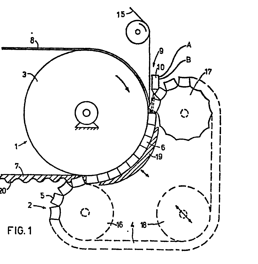
Description
Die Erfindung richtet sich auf ein Verfahren und eine Vorrichtung zum kontinuierlichen Herstellen von Gegenständen oder Beschichtungen mit kompliziert geformten Konturen, wobei ein flüssiges Material in den zwischen mindestens zwei wandernden endlosen formgebenden Flächen gebildeten Formhohlraum an einem Ende eingebracht wird, im Formhohlraum aushärtet und anschließend entformt wird.The invention relates to a method and a device for the continuous production of objects or coatings with complexly shaped contours, wherein a liquid material is introduced at one end into the mold cavity formed between at least two moving, endless shaping surfaces, cures in the mold cavity and is subsequently removed from the mold .
Es ist seit längerem bekannt, durch Aufgießen von reagierenden Polymeren auf rotierende Körper ohne Formwerkzeug eine glatte Außenbeschichtung zu erreichen.It has long been known to achieve a smooth outer coating by pouring reactive polymers onto rotating bodies without a molding tool.
Es ist auch bekannt (DE-OS 32 00 063) Zahnriemen dadurch herzustellen, daß man einen flüssigen Kunststoff mittels einer Aufgabevorrichtung in einen seitlich und eingangs seitig völlig abgedichteten Formhohlraum aus wandernden Flächen eingibt. Die eingangsseitige Abdichtung ist sehr aufwendig und störanfällig; sie stellt insbesondere dann hohe Anforderungen, wenn noch zusätzlich Verstärkungseinlagen eingeführt werden sollen.It is also known (DE-OS 32 00 063) to produce toothed belts in that a liquid plastic is completely sealed by means of a feed device into a side and entry side Enter mold cavity from migratory surfaces. The sealing on the inlet side is very complex and prone to failure; it places high demands in particular if additional reinforcement inserts are to be introduced.
Es besteht die Aufgabe, ein Verfahren und eine Vorrichtung zu schaffen, womit Gegenstände oder Beschichtungen mit kompliziert geformten Konturen aus flüssigem Material herstellbar sind, wobei eine abdichtungsfreie Zufuhr von Material und gegebenenfalls Verstärkungseinlagen möglich ist. Dabei ist auch die vollständige und gleichmäßige Ausfüllung des wandernden Formhohlraumes sicherzustellen.The object is to create a method and a device by means of which objects or coatings with complicatedly shaped contours can be produced from liquid material, with a seal-free supply of material and possibly reinforcing inserts being possible. The complete and even filling of the moving mold cavity must also be ensured.
Diese Aufgabe wird dadurch gelöst, daß die wandernden Flächen zumindest im Bereich der Materialaufgabe abwärts bewegt werden und der Strahl zugeführten Materials quer zur Vorschubrichtung der Flächen hin und her geführt wird; und daß dabei unter Berücksichtgung der Vorschubgeschwindigkeit der Flächen und der jeweiligen Weite des Hohlraumes unterhalb des Strahles, die zugeführte Materialmenge im Sinne einer gleichmäßig überschichtenden Füllung des Formhohlraumes gesteuert wird.This object is achieved in that the migrating surfaces are moved downwards at least in the area of the material feed and the jet of supplied material is guided back and forth transversely to the direction of advance of the surfaces; and that taking into account the feed speed of the surfaces and the respective width of the cavity below the jet, the amount of material supplied is controlled in the sense of a uniformly overlapping filling of the mold cavity.
Gegenüber allen bisher bekannten Verfahren erlaubt das neue Verfahren Gegenstände oder Beschichtungen herzustellen, gleichgültig, in welcher Richtung sie konturiert sind. Dabei ist eine Abdichtung der Eingangsseite des Formhohlraumes nicht erforderlich.Compared to all previously known methods, the new method allows objects or coatings to be produced, regardless of the direction in which they are contoured. It is not necessary to seal the inlet side of the mold cavity.
Vorzugsweise wird die Steuerung durch Variation der Vorschubgeschwindigkeit der wandernden Flächen bewirkt. Nach einer anderen Durchführungsform des Verfahrens wird die Steuerung bei gleichbleibender Zuführmenge durch Variation der Oszillationsgeschwindigkeit des Strahles bewirkt.The control is preferably effected by varying the feed rate of the moving surfaces. According to another embodiment of the method, the control is effected by varying the oscillation speed of the beam while the quantity supplied is constant.
Alternativ hierzu wird die Steuerung bei gleichbleibender Oszillationsgeschwindigkeit des Strahles durch Variation der Zuführmenge bewirkt.As an alternative to this, the control is effected by varying the feed quantity while the oscillation speed of the beam remains constant.
Obwohl aufgrund der heutigen Techniken beide Varianten durchführbar sind, erscheint die erste Variante vorteilhafter, weil es einfacher erscheint, mittels einer Programmsteuerung die Oszillationsgeschwindigkeit des Strahles zu variieren als die Zuführmenge zu beeinflussen. Da man bei der zweiten Variante auf die Dosierpumpen einwirken müßte, entstünde eine gewisse Trägheit im Zuführsystem.Although both variants can be carried out on the basis of today's techniques, the first variant appears to be more advantageous because it appears easier to vary the oscillation speed of the beam by means of a program control than to influence the feed quantity. Since the second variant would have to act on the metering pumps, there would be a certain inertia in the feed system.
Die Steuerung erfolgt also in der Weise, daß der hin und her gehende Strahl genau abgestimmt an Stellen geringerer Stärke des herzustellenden Gegenstandes bzw. Beschichtung schneller wandert als an Stellen größerer Stärke. Verläuft die Konturierung des herzustellenden Gegenstandes quer, so bleibt zwar die Oszillationsgeschwindigkeit während eines Hubes konstant, ändert sich aber zwischen den Hüben entsprechend dem auszufüllenden Volumen.The control is thus carried out in such a way that the back and forth beam travels more precisely in places of lower thickness of the object or coating to be produced than in areas of greater strength. If the contouring of the object to be produced runs transversely, the oscillation speed remains constant during one stroke, but changes between the strokes in accordance with the volume to be filled.
Als flüssiges Material werden vorzugsweise Polymerverbindungen, wie Polyurethanelastomere auf Basis Polyether und/oder Polyester, vorzugsweise mit einer Aushärtezeit von 0,5 bis 180 Sekunden verwendet.Polymer compounds, such as polyurethane elastomers based on polyether and / or polyester, are preferably used as the liquid material, preferably with a curing time of 0.5 to 180 seconds.
Dieses Material ist wegen seiner besonderen Eigenschaften für viele Anwendungsbereiche besonders begehrt und durch die neue Herstellungstechnik werden die Anwendungsmöglichkeiten erweitert. Selbstverständlich lassen sich aber auch Thermoplaste aus der Schmelze, Polyester oder Epoxidharze verarbeiten.Because of its special properties, this material is particularly popular for many areas of application and the new manufacturing technology extends the range of possible applications. Of course, thermoplastics from the melt, polyester or epoxy resins can also be processed.
Die Vorrichtung zur Durchführung des neuen Verfahrens geht aus von mindestens zwei umlaufenden endlosen Flächen, von denen mindestens eine sich aus einzelnen Formsegmenten zusammensetzt, wobei diese Flächen zwischen sich einen seitlich abgedichteten Formhohlraum einschließen und am Eingang des Formhohlraumes eine Aufgabevorrichtung angeordnet ist.The device for carrying out the new method is based on at least two circumferential endless surfaces, at least one of which is composed of individual mold segments, these surfaces enclosing a laterally sealed mold cavity and a feed device being arranged at the entrance of the mold cavity.
Das Neue ist darin zu sehen, daß die wandernden Flächen im Bereich der Aufgabevorrichtung abwärts gerichtet sind und das die Aufgabevorrichtung quer hin und herfahrbar ist und die Antriebe der Aufgabevorrichtung und/oder der der Aufgabevorrichtung zugeordneten Pumpe(n) mit einem Programmsteuergerät verbunden sind.What is new is that the moving surfaces in the area of the feed device are directed downwards and that the feed device can be moved back and forth and the drives of the feed device and / or the pump (s) associated with the feed device are connected to a program control device.
Dadurch wird konstruktiv eine Vereinfachung erreicht, in dem die Aufgabestelle selbst nicht abgedichtet ist sondern die Aufgabevorrichtung direkt in den offenen Eingang des Formhohlraumes hinweist. Die Koppelung des Antriebs bzw. der Pumpen oder entsprechender Elemente der Aufgabevorrichtung erlaubt es, die Zufuhrmenge des flüssigen Materials jeweils exakt auf das in jedem Zeitpunkt auszufüllende Volumen abzustimmen.This simplifies the design in that the feed point itself is not sealed, but rather the feed device is directly in the open one Entrance of the mold cavity indicates. The coupling of the drive or the pumps or corresponding elements of the feed device allows the supply quantity of the liquid material to be matched exactly to the volume to be filled in at any time.
Nach einer besonderen Ausführungsform stellt ein Rotationskörper eine der wandernden Flächen dar, dessen Umfangsfläche teilweise von den Formsegmenten der anderen wandernden Fläche unter Bildung des Formhohlraumes abgedeckt ist.According to a particular embodiment, a rotating body represents one of the moving surfaces, the peripheral surface of which is partially covered by the mold segments of the other moving surface, forming the mold cavity.
Diese Ausführungsform erlaubt das direkte Beschichten von Rotationskörpern oder die Herstellung von rotationssymmetrischen Gegenständen.This embodiment allows the direct coating of rotating bodies or the production of rotationally symmetrical objects.
Nach einer weiteren besonderen Ausführungsform besteht der Rotationskörper aus einem runderneuerungsbedürftigen Fahrzeugreifen.According to a further special embodiment, the rotating body consists of a vehicle tire in need of retreading.
Auf diese Weise gelingt es, insbesondere Polyurethangroßreifen, wie sie beispielsweise für Erdbewegungsmaschinen benutzt werden, mit relativ geringem maschinellen Aufwand mit einer neuen Laufdecke zu versehen.In this way it is possible, in particular large polyurethane tires, such as those used for earthmoving machines, to be provided with a new tread with relatively little mechanical effort.
Nach einer weiteren besonderen Ausführungsform besteht der Rotationskörper aus einem zu beschichtenden Walzenkörper.According to a further special embodiment, the rotating body consists of a roller body to be coated.
Die neue Vorrichtung erlaubt es, eine Beschichtung gleichbleibender Stärke oder eine Beschichtung mit Profilierung herzustellen.The new device allows a coating constant thickness or to produce a coating with profiling.
Bei Rotationskörpern größeren Durchmessers lassen sich gegebenenfalls zwei wandernde Gegenflächen mit Aufgabevorrichtungen anordnen, so daß in einem Arbeitsgang mehrere Schichten aufgebracht werden können. Es ist auch denkbar, sofern die seitliche Abdichtung entsprechend gestaltet ist, nach einer ersten Beschichtungsumdrehung des Rotationskörpers die beiden den Formhohlraum bildenden wandernden Flächen etwas auseinanderzufahren, so daß ein zweiter und gegebenenfalls noch weitere Beschichtungsvorgänge stattfinden können.In the case of rotating bodies of larger diameter, it is possible, if necessary, to arrange two moving counter-surfaces with feed devices, so that several layers can be applied in one operation. It is also conceivable, provided that the lateral seal is designed accordingly, to move the two moving surfaces forming the mold cavity slightly apart after a first coating revolution of the rotating body, so that a second and possibly further coating processes can take place.
Es versteht sich auch, daß nach einem ersten Beschichtungsvorgang entweder der Rotationskörper einer zweiten Gegenfläche zugeführt wird oder alternativ eine zweite Gegenfläche dem Rotationskörper. Diese Ausführungsform bietet sich für größere Stückzahlen an.It is also understood that after a first coating process either the rotary body is fed to a second counter surface or, alternatively, a second counter surface is fed to the rotary body. This embodiment is suitable for larger quantities.
Nach einer weiteren besonderen Ausführungsform der Vorrichtung bestehen die wandernden Flächen aus über Umlenkwalzen umlaufenden endlosen parallel angeordneten Bändern, von denen mindestens eines Formsegmente aufweist, wobei den Bändern im Bereich des gebildeten Formhohlraumes rückseitig Abstützungen zugeordnet sind.According to a further special embodiment of the device, the moving surfaces consist of endless belts arranged in parallel and rotating about deflection rollers, at least one of which has shaped segments, supports being assigned to the belts in the area of the formed mold cavity on the back.
Entgegen den vorbeschriebenen Ausführungsformen, bei denen der Formhohlraum gekrümmt ist, verläuft er hier gerade. Diese Ausführungsform eignet sich besonders gut für die Herstellung von bandartigen endlosen Gegenständen größerer Dimensionen.Contrary to the previously described embodiments, in which the mold cavity is curved, it runs straight here. This embodiment is particularly well suited for the production of band-like endless objects of larger dimensions.
Es versteht sich, daß die neue Vorrichtung durch an sich bekannte Hilfsvorrichtungen zum Einführen von Verstärkungseinlagen in Form von Gewebebändern, endlosen Rovings, Faservliesen usw. aus Glasfasern, Kunststoffen oder Metall ergänzt sein kann.It goes without saying that the new device can be supplemented by auxiliary devices known per se for introducing reinforcing inserts in the form of fabric strips, endless rovings, non-woven fabrics etc. made of glass fibers, plastics or metal.
In der Zeichnung ist die neue Vorrichtung in mehreren Ausführungsbeispielen für verschiedene Anwendungen rein schematisch dargestellt und nachstehend näher erläutert. Es zeigen:
Figur 1 eine Ausführungsform der Vorrichtung zum Herstellen von Zahnriemen in der Seitenansicht,Figur 2 eine Frontansicht der Materialaufgabe zur Vorrichtung gemäßFigur 1,Figur 3 eine Ausführungsform der Vorrichtung zum Runderneuern von Fahrzeugreifen in der Seitenansicht,Figur 4 einen Schnitt gemäß Linie A, B inFigur 3,Figur 5 eine Ausführungsform der Vorrichtung zum Herstellen eines Förderbandes mit Fördertaschen,Figur 6 einen gefertigten Walzenbezug in räumlicher Darstellung,Figur 7 einen Querschnitt durch den Walzenbezug gemäßFigur 6 und- Figur 8 einen Querschnitt durch eine abgewandelte Ausführungsform des Walzenbezuges gemäß
Figur 6.
- FIG. 1 shows an embodiment of the device for producing toothed belts in a side view,
- FIG. 2 shows a front view of the material feed for the device according to FIG. 1,
- FIG. 3 shows an embodiment of the device for retreading vehicle tires in a side view,
- FIG. 4 shows a section along line A, B in FIG. 3,
- FIG. 5 shows an embodiment of the device for producing a conveyor belt with conveyor pockets,
- FIG. 6 shows a finished roller cover in a spatial representation,
- 7 shows a cross section through the roll cover according to FIG. 6 and
- 8 shows a cross section through a modified embodiment of the roller cover according to FIG. 6.
In Figur 1, 2 besteht die Vorrichtung aus zwei formgebenden Flächen 1,2. Die Fläche 1 stellt die Umfangsfläche einer Trommel 3 dar. Die Fläche 2 besteht aus einer endlosen Kette 4 aus Formsegmenten 5. Die formgebenden Flächen 1, 2 schließen zwischen sich einen Formhohlraum 6 ein, welcher sich über einen gewissen Teil des Umfanges der Trommel 3 erstreckt. Die Länge dieses Formhohlraumes 6 ist von der Vorschubgeschwindigkeit der Flächen 1, 2 in der Weise abhängig, daß der produzierte Gegenstand beim Verlassen des Formhohlraumes 6 bereits Formstabilität aufweisen soll. über die Trommel 3 wird eine Trägermaterialbahn 8 aus Gewebe zugeführt, welche von dem zugegebenen flüssigen Material, einem thermoplastischen Polyurethanelastomer in flüssiger Form, durchtränkt wird, bevor dieses Material aushärtet. Mit einer Aufgabevorrichtung 9, welche gleichzeitig als Mischaggregat dient, werden flüssige Komponenten A (Polyol) und B (Isocyanat) zugeführt und miteinander vermischt, wobei sie reagieren und das Gemisch in den Formhohlraum 6 eingegeben.In Figure 1, 2, the device consists of two
Die Aufgabevorrichtung 9 besteht aus einem Mischkopf 10, welcher auf Schienen 11 quer zur Vorschubrichtung der Flächen 1, 2 hin und herfahrbar ist. Als Antrieb dient ein Elektromotor 12 und Kurbeltrieb 13 mit einstellbarem Hub. Die Hubgeschwindigkeit der Aufgabevorrichtung 9 muß so groß sein, daß sich die neu aufgelegte Schicht jeweils mit der darunterliegenden verbindet, bevor diese ausgehärtet ist. Die Aufgabevorrichtung 9 ist mit einem schematisch angedeuteten Programmsteuergerät 14 gekoppelt. Es gibt in der Weise Befehle, daß (bei gleichförmiger Vorschubgeschwindigkeit der Flächen 1, 2) wenn jeweils ein Zahn 20 des Zahnriemens 7 zu bilden ist, die Aufgabevorrichtung 9 entsprechend langsamer oszilliert, so daß genügend Material zugeführt wird. In den Formhohlraum 6 wird zusätzlich eine Verstärkungseinlage 15 kontinuierlich eingeführt. Die Kette 4 aus Formsegmenten 5 läuft über Umlenkrollen 16, 17 und ein Spannrad 18 um. Die Umlenkrollen 16, 17 sind zur Trommel 3 hin verschiebbar, so daß erforderlichenfalls die Höhe des Formhohlraumes einstellbar ist. Im Bereich der Umschlingung der Trommel 3 durch die Kette 4 aus Formsegmenten 5 ist letztere zwischen den Umlenkrollen 16, 17 durch einen Gleitschuh 19 abgestützt.The
In Figur 3,4 ist die Vorrichtung in ähnlicher Weise aufgebaut wie in Figur 1,2; es werden deshalb die gleichen Bezugszeichen benutzt. Die Abwandlung besteht lediglich darin, daß anstelle der Trommel 3 eine drehbar gelagerte Felge 3a mit einem runderneuerungsbedürftigen Fahrzeugreifen 8a als Trägermaterial vorgesehen ist. Die Formsegmente 5 der Kette 4 weisen jedoch in diesem Falle kein negatives Zahnprofil auf sondern ein solches für Reifen. An der Felge seitlich angeordnete Dichtringe 21 sorgen für die seitliche Abdichtung des gebildeten Hohlraumes 6. In den Hohlraum 6 läuft eine Verstärkungsbahn 15 ein.In Figure 3.4, the device is constructed in a similar manner as in Figure 1,2; the same reference numerals are therefore used. The modification is only that instead of the
Die Runderneuerung erfolgt während einer einzigen Umdrehung des Reifens 8a. Der fertige Reifen ist mit 7a bezeichnet.The retreading takes place during a single revolution of the
Die Vorrichtung gemäß Figur 5 weicht von denjenigen gemäß Figur 1,2 bzw. 3,4 ab. Bewegte Flächen 31, 32 laufen über Umlenkräder 33, 34 bzw. 35, 36 parallel zueinander um. Die bewegte Fläche 31 ist durch ein umlaufendes Band 37 gebildet, die bewegte Fläche 32 durch eine Kette 38 aus Formsegmenten 39. Dazwischen ist der Formhohlraum 40 gebildet. Im Bereich des Formhohlraumes 40 sind das Band 37 und die Kette 38 bzw. die Formsegmente 39 durch Gleitplatten 41, 42 abgestützt. In den Formhohlraum 40 laufen zwei Verstärkungsbahnen 43, 44 aus Gewebe ein. Mittels der Aufgabevorrichtung 45, welche denjenigen gemäß Figur 1, 2 entspricht, wird ein Polyurethanelastomer bildendes Reaktionsgemisch aufgegeben. Bei dem herzustellenden Gegenstand handelt es sich um ein Förderband 46 mit Fördertaschen 47. Die Formsegmente 39 sind so gestaltet, daß sie jeweils einerseits das Innenprofil der Fördertaschen und andererseits deren Außenprofil bilden.The device according to FIG. 5 differs from those according to FIGS. 1, 2 and 3, 4. Moving
Der Walzenbezug 61 gemäß Figur 6, 7 besitzt Umfangswülste 62, zwischen denen sich ein flacher Umfangsabschnitt 63 erstreckt. Dieser Walzenbezug 61 wurde in einem einzigen Beschichtungsgang auf einer Vorrichtung gemäß Figur 1, 2 mit entsprechend gestalteten Formsegmenten hergestellt.The
Der Walzenbezug 61 gemäß Figur 8 wurde durch mehrmaliges Beschichten gefertigt, wobei auf eine Grundschicht A gleicher Stärke und hoher Härte eine Schicht B mittlerer Härte mit Umfangswülsten 62 aufgebracht wurde, welche wiederum mit einer Schicht C weicher Härte abgedeckt wurde, wobei die Umfangswülste 62 noch verstärkt wurden.The
Verwendet wird die Vorrichtung nach Fig. 1, 2. Die Flächen 1, 2, d.h. die Trägerbahn 8 sowie die Formsegmente 5 wandern mit einer Geschwindigkeit von 0,314 m/min. Der Querschnitt des Formhohlraumes 6 schwankt während des Vorschubes zwischen einem Minimalwert von 50 cm2 und einem Maximalwert von 250 cm2. Da die Fläche 1 eben ist, läßt sich fortlaufend die Höhe der Kontur der einlaufenden Formsegmente 5 elektronisch abtasten und die Oszillationsgeschwindigkeit der Aufgabevorrichtung 9 in Abhängigkeit davon steuern. Der Ausstoß der Aufgabevorrichtung 9 beträgt kontinuierlich 3,34 kg/min. Aufgegeben wird ein Gemisch aus
100 Gewichtsteilen TDI-Isocyanat und 10,4 Gewichtsteilen Diamin-Gemisch
die Verfestigungszeit beträgt 30 Sekunden.The device according to FIGS. 1, 2 is used. The
100 parts by weight of TDI isocyanate and 10.4 parts by weight of diamine mixture
the setting time is 30 seconds.
Runderneuert wird ein Reifen mit der Vorrichtung gemäß Fig. 3, 4. Die Felge 3a rotiert mit 0,25 U/min. Die Aufgabevorrichtung 9 stößt 9,5 kg/min. reaktives Gemisch aus, bestehend aus
100 Gewichtsteilen TDI-Isocyanat und 36,6 Gewichtsteilen Polyester-Diamin-Gemisch.A tire is retreaded with the device according to FIGS. 3, 4. The
100 parts by weight of TDI isocyanate and 36.6 parts by weight of polyester-diamine mixture.
Die Verfestigungszeit beträgt 45 Sekunden.The hardening time is 45 seconds.
Claims (10)
Priority Applications (1)
| Application Number | Priority Date | Filing Date | Title |
|---|---|---|---|
| AT85106543T ATE42058T1 (en) | 1984-06-08 | 1985-05-29 | METHOD AND DEVICE FOR CONTINUOUS MANUFACTURE OF OBJECTS OR COATINGS WITH COMPLICATED CONTOURS. |
Applications Claiming Priority (2)
| Application Number | Priority Date | Filing Date | Title |
|---|---|---|---|
| DE19843421363 DE3421363A1 (en) | 1984-06-08 | 1984-06-08 | METHOD AND DEVICE FOR CONTINUOUSLY PRODUCING OBJECTS OR COATINGS WITH COMPLICELY SHAPED CONTOURS |
| DE3421363 | 1984-06-08 |
Publications (3)
| Publication Number | Publication Date |
|---|---|
| EP0167775A2 true EP0167775A2 (en) | 1986-01-15 |
| EP0167775A3 EP0167775A3 (en) | 1987-03-25 |
| EP0167775B1 EP0167775B1 (en) | 1989-04-12 |
Family
ID=6237925
Family Applications (1)
| Application Number | Title | Priority Date | Filing Date |
|---|---|---|---|
| EP85106543A Expired EP0167775B1 (en) | 1984-06-08 | 1985-05-29 | Method and apparatus for continuously producing objects or coatings having complicates outlines |
Country Status (6)
| Country | Link |
|---|---|
| US (1) | US4755334A (en) |
| EP (1) | EP0167775B1 (en) |
| JP (1) | JPS6149814A (en) |
| AT (1) | ATE42058T1 (en) |
| CA (1) | CA1257760A (en) |
| DE (2) | DE3421363A1 (en) |
Cited By (3)
| Publication number | Priority date | Publication date | Assignee | Title |
|---|---|---|---|---|
| DE3840753A1 (en) * | 1988-12-03 | 1990-06-07 | Ferro Kunststoffe Gmbh | METHOD FOR FLOW COATING A COATING CARRIER AND SYSTEM FOR IMPLEMENTING THE METHOD |
| EP0686471A3 (en) * | 1994-06-07 | 1996-06-05 | Bando Chemical Ind | Method and apparatus for producing cleaning blades |
| EP0775564A3 (en) * | 1995-11-24 | 1998-10-21 | Bando Kagaku Kabushiki Kaisha | Blade for electrophotographic devices and production method and production apparatus for same |
Families Citing this family (15)
| Publication number | Priority date | Publication date | Assignee | Title |
|---|---|---|---|---|
| FR2571310B1 (en) * | 1984-10-04 | 1987-01-30 | Michelin & Cie | PREVULCANIZED TREAD FOR RETREADING TIRES AND APPARATUS FOR PRODUCING SUCH A TREAD |
| DE4035610A1 (en) * | 1990-11-09 | 1992-05-14 | Basf Ag | METHOD FOR PRODUCING FIBER COMPOSITES |
| IT1241332B (en) * | 1990-12-04 | 1994-01-10 | Firestone Int Dev Spa | METHOD FOR THE REALIZATION OF A REINFORCED COMPONENT OF A VEHICLE TIRE CASE |
| US5266021A (en) * | 1991-10-10 | 1993-11-30 | Jacobson Theodore L | Apparatus for continuous forming of complex molded shapes |
| US6007319A (en) * | 1993-11-30 | 1999-12-28 | Continuous Molding, Inc. | Continuous forming of complex molded shapes |
| ES2137858B1 (en) * | 1997-07-15 | 2000-08-16 | Breat Sl | PROCEDURE AND APPARATUS FOR THE MANUFACTURE OF HONEYCOMBS FOR BEEKEEPING. |
| US6623667B2 (en) | 2001-02-28 | 2003-09-23 | 3M Innovative Properties Company | Method for continuous fabrication of structured surface light guides |
| DE10206510B4 (en) * | 2002-02-16 | 2004-02-12 | Breco Antriebstechnik Breher Gmbh & Co. | Method and device for manufacturing a toothed belt |
| US7824595B2 (en) * | 2004-08-13 | 2010-11-02 | Perma-Pipe, Inc. | Method and system for cast molding a fluid conduit |
| US20080072988A1 (en) * | 2006-08-22 | 2008-03-27 | Perma-Pipe, Inc. | Glass Syntactic Polyurethane Insulated Product |
| EP1958613A1 (en) * | 2007-02-15 | 2008-08-20 | Polichem S.A. | Dermal film-forming liquid formulations for drug release to skin |
| MX2014007112A (en) | 2011-12-14 | 2014-09-08 | Gates Corp | System and method of making open-ended thermoplastic belting. |
| WO2016190874A1 (en) * | 2015-05-28 | 2016-12-01 | Compagnie Generale Des Etablissements Michelin | System with plug assembly for continuous molding and curing of tire tread |
| JP2018531810A (en) * | 2015-07-30 | 2018-11-01 | ハバシット アクチエンゲゼルシャフト | Flightless monolithic belt manufacturing system and manufacturing method |
| CN109205193A (en) * | 2018-10-26 | 2019-01-15 | 广东阿博特数码纸业有限公司 | A kind of coating machine tape loop device |
Family Cites Families (8)
| Publication number | Priority date | Publication date | Assignee | Title |
|---|---|---|---|---|
| US3226457A (en) * | 1961-03-23 | 1965-12-28 | Dow Chemical Co | Method and apparatus for continuously forming plastic articles |
| US3267191A (en) * | 1961-07-07 | 1966-08-16 | Us Rubber Co | Method of forming a rubber sheet having stubs extending from one surface |
| US3660548A (en) * | 1963-11-06 | 1972-05-02 | Toyo Tire & Rubber Co | Method for continuously producing foamed panels having uniform properties |
| DE1504113B2 (en) * | 1965-02-20 | 1971-12-02 | Continental Gummi Werke AG, 3000 Hannover | METHOD AND DEVICE FOR MANUFACTURING ENDLESS BELTS AND CONVEYED GOODS |
| GB1101786A (en) * | 1966-03-08 | 1968-01-31 | Continental Gummi Werke Ag | Improvements in or relating to endless belts |
| US3487143A (en) * | 1966-11-30 | 1969-12-30 | Goodrich Co B F | Apparatus and method for the continuous casting of polyurethane flat belting |
| DE2924357A1 (en) * | 1979-06-16 | 1980-12-18 | Norddeutsche Seekabelwerke Ag | METHOD FOR THE CONTINUOUS PRODUCTION OF ARMED PROFILE TAPES |
| DE3200063C2 (en) * | 1982-01-04 | 1984-06-28 | Breco Kunststoffverarbeitungs-Gesellschaft mbH & Co KG, 4952 Porta Westfalica | Process for the production of a reinforced toothed belt with a fabric cover |
-
1984
- 1984-06-08 DE DE19843421363 patent/DE3421363A1/en not_active Withdrawn
-
1985
- 1985-05-22 CA CA000482091A patent/CA1257760A/en not_active Expired
- 1985-05-29 AT AT85106543T patent/ATE42058T1/en not_active IP Right Cessation
- 1985-05-29 EP EP85106543A patent/EP0167775B1/en not_active Expired
- 1985-05-29 DE DE8585106543T patent/DE3569345D1/en not_active Expired
- 1985-06-05 US US06/741,513 patent/US4755334A/en not_active Expired - Fee Related
- 1985-06-06 JP JP60121640A patent/JPS6149814A/en active Granted
Cited By (3)
| Publication number | Priority date | Publication date | Assignee | Title |
|---|---|---|---|---|
| DE3840753A1 (en) * | 1988-12-03 | 1990-06-07 | Ferro Kunststoffe Gmbh | METHOD FOR FLOW COATING A COATING CARRIER AND SYSTEM FOR IMPLEMENTING THE METHOD |
| EP0686471A3 (en) * | 1994-06-07 | 1996-06-05 | Bando Chemical Ind | Method and apparatus for producing cleaning blades |
| EP0775564A3 (en) * | 1995-11-24 | 1998-10-21 | Bando Kagaku Kabushiki Kaisha | Blade for electrophotographic devices and production method and production apparatus for same |
Also Published As
| Publication number | Publication date |
|---|---|
| JPH0356645B2 (en) | 1991-08-28 |
| JPS6149814A (en) | 1986-03-11 |
| EP0167775A3 (en) | 1987-03-25 |
| DE3569345D1 (en) | 1989-05-18 |
| EP0167775B1 (en) | 1989-04-12 |
| ATE42058T1 (en) | 1989-04-15 |
| DE3421363A1 (en) | 1985-12-12 |
| US4755334A (en) | 1988-07-05 |
| CA1257760A (en) | 1989-07-25 |
Similar Documents
| Publication | Publication Date | Title |
|---|---|---|
| EP0167775B1 (en) | Method and apparatus for continuously producing objects or coatings having complicates outlines | |
| EP0166245A2 (en) | Method and apparatus for continuously forming tubular hollow bodies, in particular hoses, tubes and inner liners for them, from a liquid material, such as a reaction mixture or a melt | |
| EP0158623A1 (en) | Process for producing a fibre reinforced plastics leaf spring | |
| DE60314872T2 (en) | METHOD AND DEVICE FOR PRODUCING ELASTOMER MATERIAL COMPONENTS OF VEHICLE WHEEL TIRES | |
| DE2334796C2 (en) | Method and apparatus for producing a pipe made of concrete or the like. | |
| DE10222015A1 (en) | Flat plastic belt manufacturing equipment has a second station with a deflection roll forming an adjustable gap against a forming wheel used to complete the second part of the belt | |
| WO2011113558A2 (en) | Method, system and prepreg for producing fibre-reinforced moulded parts in a moulding press | |
| DE3929820C1 (en) | ||
| WO2004000525A1 (en) | Method and device for the injection moulding of multi-component fibre-reinforced moulded parts | |
| DE2328794A1 (en) | PLASTIC VEHICLE WHEEL | |
| DE102011009506B4 (en) | Apparatus for producing hollow molded components from a fiber composite material | |
| EP0754794A2 (en) | Machine for the production of prefabricated reinforcing webs | |
| EP0005423A1 (en) | Apparatus for casting or injection moulding vehicle tyres | |
| DE60111798T2 (en) | High-speed cutting device for cutting reinforcing elements for pneumatic tires. | |
| DE4113056A1 (en) | Processing recycling rubber materials - by horizontally moved machine which mixes scrap and binder and drops it onto moving belt which passes it through hot plates press | |
| DE102009018131B4 (en) | Method for producing a three-dimensional structural element and device for producing a three-dimensional structural element | |
| DE202009003295U1 (en) | Device for producing flat belts | |
| DE69028080T2 (en) | PRODUCTION OF TIRE LINK AND DEVICE THEREFOR | |
| DE102004004407A1 (en) | Coating equipment for application of resin mixture onto carrier layer or reinforcing fabric has resin application head programmed to move along linear guides and has interchangeable resin feed system | |
| DE3903067C3 (en) | Process for producing a rotor for rotary piston machines, and rotor manufactured using the process | |
| DE19531184C2 (en) | Elastomer composite profile and method and device for its production | |
| DE69625707T2 (en) | METHOD AND DEVICE FOR PRODUCING STRUCTURES | |
| DE1729771A1 (en) | Process for the production of a reinforcement element for objects made of rubber | |
| DE2152124B2 (en) | Machine for producing elongated concrete building elements | |
| EP4116072B1 (en) | Method for producing a profiled elastomeric product |
Legal Events
| Date | Code | Title | Description |
|---|---|---|---|
| PUAI | Public reference made under article 153(3) epc to a published international application that has entered the european phase |
Free format text: ORIGINAL CODE: 0009012 |
|
| 17P | Request for examination filed |
Effective date: 19850529 |
|
| AK | Designated contracting states |
Designated state(s): AT BE DE FR GB IT SE |
|
| PUAL | Search report despatched |
Free format text: ORIGINAL CODE: 0009013 |
|
| AK | Designated contracting states |
Kind code of ref document: A3 Designated state(s): AT BE DE FR GB IT SE |
|
| 17Q | First examination report despatched |
Effective date: 19871028 |
|
| GRAA | (expected) grant |
Free format text: ORIGINAL CODE: 0009210 |
|
| AK | Designated contracting states |
Kind code of ref document: B1 Designated state(s): AT BE DE FR GB IT SE |
|
| REF | Corresponds to: |
Ref document number: 42058 Country of ref document: AT Date of ref document: 19890415 Kind code of ref document: T |
|
| ITF | It: translation for a ep patent filed | ||
| GBT | Gb: translation of ep patent filed (gb section 77(6)(a)/1977) | ||
| REF | Corresponds to: |
Ref document number: 3569345 Country of ref document: DE Date of ref document: 19890518 |
|
| ET | Fr: translation filed | ||
| PLBE | No opposition filed within time limit |
Free format text: ORIGINAL CODE: 0009261 |
|
| STAA | Information on the status of an ep patent application or granted ep patent |
Free format text: STATUS: NO OPPOSITION FILED WITHIN TIME LIMIT |
|
| 26N | No opposition filed | ||
| PGFP | Annual fee paid to national office [announced via postgrant information from national office to epo] |
Ref country code: FR Payment date: 19900426 Year of fee payment: 6 |
|
| PGFP | Annual fee paid to national office [announced via postgrant information from national office to epo] |
Ref country code: AT Payment date: 19900507 Year of fee payment: 6 |
|
| ITTA | It: last paid annual fee | ||
| PG25 | Lapsed in a contracting state [announced via postgrant information from national office to epo] |
Ref country code: AT Effective date: 19910529 |
|
| PG25 | Lapsed in a contracting state [announced via postgrant information from national office to epo] |
Ref country code: FR Effective date: 19920131 |
|
| REG | Reference to a national code |
Ref country code: FR Ref legal event code: ST |
|
| PGFP | Annual fee paid to national office [announced via postgrant information from national office to epo] |
Ref country code: SE Payment date: 19920424 Year of fee payment: 8 |
|
| PGFP | Annual fee paid to national office [announced via postgrant information from national office to epo] |
Ref country code: GB Payment date: 19920505 Year of fee payment: 8 |
|
| PGFP | Annual fee paid to national office [announced via postgrant information from national office to epo] |
Ref country code: BE Payment date: 19920527 Year of fee payment: 8 |
|
| PG25 | Lapsed in a contracting state [announced via postgrant information from national office to epo] |
Ref country code: GB Effective date: 19930529 |
|
| PG25 | Lapsed in a contracting state [announced via postgrant information from national office to epo] |
Ref country code: SE Effective date: 19930530 |
|
| PG25 | Lapsed in a contracting state [announced via postgrant information from national office to epo] |
Ref country code: BE Effective date: 19930531 |
|
| BERE | Be: lapsed |
Owner name: BAYER A.G. Effective date: 19930531 |
|
| GBPC | Gb: european patent ceased through non-payment of renewal fee |
Effective date: 19930529 |
|
| EUG | Se: european patent has lapsed |
Ref document number: 85106543.3 Effective date: 19931210 |
|
| PGFP | Annual fee paid to national office [announced via postgrant information from national office to epo] |
Ref country code: DE Payment date: 20000413 Year of fee payment: 16 |
|
| PG25 | Lapsed in a contracting state [announced via postgrant information from national office to epo] |
Ref country code: DE Free format text: LAPSE BECAUSE OF NON-PAYMENT OF DUE FEES Effective date: 20020301 |