EP0167390A2 - Verfahren zur automatischen Steuerung der Fugenabtastung beim Lichtbogenschweissen - Google Patents
Verfahren zur automatischen Steuerung der Fugenabtastung beim Lichtbogenschweissen Download PDFInfo
- Publication number
- EP0167390A2 EP0167390A2 EP85304714A EP85304714A EP0167390A2 EP 0167390 A2 EP0167390 A2 EP 0167390A2 EP 85304714 A EP85304714 A EP 85304714A EP 85304714 A EP85304714 A EP 85304714A EP 0167390 A2 EP0167390 A2 EP 0167390A2
- Authority
- EP
- European Patent Office
- Prior art keywords
- torch
- weaving
- groove
- welding
- arc
- Prior art date
- Legal status (The legal status is an assumption and is not a legal conclusion. Google has not performed a legal analysis and makes no representation as to the accuracy of the status listed.)
- Granted
Links
Images

Classifications
-
- B—PERFORMING OPERATIONS; TRANSPORTING
- B23—MACHINE TOOLS; METAL-WORKING NOT OTHERWISE PROVIDED FOR
- B23K—SOLDERING OR UNSOLDERING; WELDING; CLADDING OR PLATING BY SOLDERING OR WELDING; CUTTING BY APPLYING HEAT LOCALLY, e.g. FLAME CUTTING; WORKING BY LASER BEAM
- B23K9/00—Arc welding or cutting
- B23K9/12—Automatic feeding or moving of electrodes or work for spot or seam welding or cutting
- B23K9/127—Means for tracking lines during arc welding or cutting
Definitions
- the present invention relates to an arc welding method of the type in which the arc itself causes the movement of a torch to accurately follow the joint to be welded, and more particularly the invention relates to an automatic tracing control method for the arc welding torch.
- sensors of the above type have been used in the past and they include the contact types, such as, the differential transformer, potentiometer and limit switch types and the non-contact types, such as, the electromagnetic and optical position detecting types.
- the contact types such as, the differential transformer, potentiometer and limit switch types
- the non-contact types such as, the electromagnetic and optical position detecting types.
- the use of these sensors requires that a sensor or specific device be positioned near the torch in any case, it is necessary to maintain a predetermined distance between the sensing position and the controlled system position due to the dimensional limitation and it has been possible to realize only such practical control systems which have a limited accuracy despite their complicated constructions and in which the torch position is controlled by providing the sensor output with a time differential corresponding to the dimension of the spacing.
- the movement of the torch in its axial direction is controlled by the driving mechanism so that a predetermined arc voltage is maintained if the welding power source is a DC constant current source and a predetermined welding current is maintained if the welding power source is one having a DC constant voltage characteristic.
- the turning point of the weaving operation is set to each point where the displacement or position of the torch in its axial direction attains a predetermined value thus causing the torch to always weave within the width of the groove parallelly to the groove face and performing a tracing operation and also the height from the base metal surface at the joint to be welded to the terminal end of the weaving is always held constant thereby performing the arc welding.
- the preset values of the welding conditions including the welding current, arc voltage, welding speed, etc., are corrected in accordance with the separatina determined algorithms and in this way the desired metal deposition as well as the proper penetration bead in the case of the one-side welding are always ensured.
- the automatic tracing control method is so designed that in the arc welding effected by moving the welding torch in its axial direction such that the arc voltage or the welding current is maintained at a predetermined value thereby maintaining the arc length constant and weaving the torch in the width direction of the groove with respect to the welding direction while changing the direction of the weaving each time the axial displacement or position of the torch attains a predetermined value, the control method performs a series of control operations comprising detecting the positions of the terminal ends for each weaving cycle from the weaving stroke of the torch in the groove width direction, establishing a predetermined small area on the center side from each of the terminal ends, simultaneously increasing the speed of the.axial movement and decreasing the speed of the weaving-direction (width-direction) movement each time the weaving position of the torch in the groove-width direction enters each of the small areas from the groove center side, restoring the weaving-direction (width-direction) speed of the torch to the initial value each time the direction of the weaving is changed and restoring the
- numeral 1 designates a base metal, 2 a welding electrode positioned opposite to and inside the groove end faces of the base metal 1, and 3 a torch holding the electrode 2 such that a welding arc is produced between the electrode 2 and the base metal 1 by a constant current source.
- Fig. 1 the torch 3 is moved to the right in the Figure so as to spread a weld metal from a point A toward a point C along one groove slope 4.
- the torch 3 in order to maintain the arc voltage constant at the value of the point A, the torch 3 is vertically moved in response to changes in the vertical distance from the groove face (4, 5, 6) to the electrode forward end so as to always control constant the distance between the electrode 2 held by the torch 3 and the groove face, that is, the arc length.
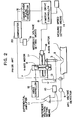
- Fig. 2 shows an example of the prior art control circuit for controlling the movement of the torch.
- numeral 7 designates a vertical- direction (Y-axis) driving mechanism for vertically moving the torch 3, and 17 a width-direction (X-axis) driving mechanism for horizontally moving the torch 3.
- the driving mechanisms 7 and 17 are respectively operated by a Y-axis motor 8 and an X-axis motor 16.
- the vertical movement of the torch 3 is effected by obtaining the difference between a detection signal from an arc voltage detector 9 and a reference arc voltage preset by reference arc voltage setting means 10 by a differential amplifier 11 and controlling the torch 3 through a Y-motor drive controller 12 so as to always reduce the difference to zero.
- the arc point successively passes through the points A, B and C and thus it moves to follow the shape of the groove.
- the changes in the vertical movement of the torch 3 are detected as a voltage signal which varies with time by a displacement meter 13 (hereinafter referred to as a Y-axis displacement meter).
- This Y-axis displacement voltage signal is applied to one input of a comparator 20 whose other input receives a preset reference voltage e from reference voltage setting means 19 for comparison with the former.
- the comparator 20 When the Y-axis displacement is equal to the reference voltage e o , the comparator 20 generates an output signal so that in accordance with this output signal a changeover pulse generator 18 sends to an X-motor drive controller 15 a signal for reversing the direction of rotation of the X-axis motor 16 and the direction of the X-axis weaving is reversed.
- a changeover pulse generator 18 sends to an X-motor drive controller 15 a signal for reversing the direction of rotation of the X-axis motor 16 and the direction of the X-axis weaving is reversed.
- numeral 14 designates X-axis weaving speed setting means.
- the dynamic characteristic is affected by the gain a of the Y-axis drive differential amplifier 11, the X-axis weaving speed V x or the weaving speed preset by the weaving speed setting means 14 and the groove angle 0 and particularly it is effective to increase the gain and decrease the weaving speed v x as the groove angle. 0 is decreased.
- the gain ⁇ is increased, the Y-axis gain is excessively increased in the groove central portion (the B-C area) so that the torch responds to even a slight variation of the arc voltage and a detrimental effect is produced on the result of the welding.
- the weaving speed v x cannot be decreased so much due to the limitation imposed by the welding heat input condition.
- the conventional control method Including the above-mentioned dynamic characteristic is applicable only under such conditions where the groove angle is not so small and also the welding method provides a relatively stable arc.
- the present invention provides an automatic groove tracing control method which expands the limitations on the application of the conventional method such as shown in Fig. 2 and which ensures greater accuracy and stable welding results, and the method is so designed that the above-mentioned required dynamic characteristic is brought into full play only on the slopes of the groove and principally it is rather aimed at the static stability of the welding in the groove central portion.
- the control method of the invention will now be described in greater detail with reference again to Fig. 1.
- the X-axis positions at the end points A and D are stored for each weaving cycle so that small area ⁇ L 6 R are preliminarily defined toward the groove center from these stored positioned and these small areas are distinguished from the groove central area therebetween (hereinafter referred to as an L area).
- the L area can be determined by subtracting the values of the small areas ⁇ L and ⁇ R from the values of the points A and D stored during the preceding weaving,cycle.
- the values of ⁇ L and ⁇ R are preset as the minimum values required for the tracing control and these values are about lmm in terms of X-axis displacements.
- the Y-axis gain is set to a low-gain relatively small value ⁇ 1 and the weaving speed is also set to the proper-value v xi selected according to the welding conditions thus driving the torch.
- the gain is changed to a high-gain value ⁇ 2 ( ⁇ 2 > ⁇ 1 ) and the weaving speed is changed to a low-speed value v x2 (v x2 ⁇ v x1 ) ' .Thus, the torch is allowed to move up the groove slope C-D with a fast response.
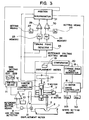
- Fig. 3 is a block diagram in which a control circuit of this invention for switching each of the Y-axis gain and the weaving speed between two values is added to the conventional circuit shown in Fig. 2 and the same component parts as shown in Fig. 2 are designated by the same reference numerals.
- numeral 24 desi- nates a turning point detector responsive to the inputs from an X-axis displacement meter 23 and the X-motor drive controller 15 to detect the turning points for each weaving cycle and store and update the values of X and X in memories 25 and 26, respectively, for each cycle of the weaving.
- the X-axis torch position discriminator 31 comprises a plurality of comparators and the present position and the direction of movement of the torch are determined according to the inputs from the X-axis displacement meter 23 and the X-motor drive controller 15 thereby discriminating the position of the torch in the X-axis direction.
- Switch means 21 is operated so that the Y-axis gain is changed to the high gain value ⁇ 2 preset by gain setting means 22B when the torch is in the small area ⁇ L or ⁇ R and to the normal gain value preset by gain setting means 22A when the torch is in the L area.
- the X-motor drive controller 15 is controlled such that the torch is moved at the preset value v X2 of weaving speed setting means 14B only during the small area between the time that the torch enters the small area ⁇ L or ⁇ R from the L area and the time that the direction of the weaving is reversed and the torch is moved at the high preset value of weaving speed setting means 14A in other circumstances.
Landscapes
- Engineering & Computer Science (AREA)
- Physics & Mathematics (AREA)
- Plasma & Fusion (AREA)
- Mechanical Engineering (AREA)
- Butt Welding And Welding Of Specific Article (AREA)
- Arc Welding In General (AREA)
Applications Claiming Priority (2)
| Application Number | Priority Date | Filing Date | Title |
|---|---|---|---|
| JP137245/84 | 1984-07-04 | ||
| JP59137245A JPS6117365A (ja) | 1984-07-04 | 1984-07-04 | 自動ならい制御方法 |
Publications (3)
| Publication Number | Publication Date |
|---|---|
| EP0167390A2 true EP0167390A2 (de) | 1986-01-08 |
| EP0167390A3 EP0167390A3 (en) | 1986-07-30 |
| EP0167390B1 EP0167390B1 (de) | 1988-04-27 |
Family
ID=15194160
Family Applications (1)
| Application Number | Title | Priority Date | Filing Date |
|---|---|---|---|
| EP85304714A Expired EP0167390B1 (de) | 1984-07-04 | 1985-07-02 | Verfahren zur automatischen Steuerung der Fugenabtastung beim Lichtbogenschweissen |
Country Status (5)
| Country | Link |
|---|---|
| US (1) | US4639573A (de) |
| EP (1) | EP0167390B1 (de) |
| JP (1) | JPS6117365A (de) |
| CA (1) | CA1234186A (de) |
| DE (1) | DE3562328D1 (de) |
Cited By (3)
| Publication number | Priority date | Publication date | Assignee | Title |
|---|---|---|---|---|
| EP0562111A4 (de) * | 1990-04-17 | 1993-05-14 | Komatsu Mfg Co Ltd | Abstandsteuerverfahren und -vorrichtung einer plasmaschneidmaschine. |
| EP0667204A1 (de) * | 1994-02-14 | 1995-08-16 | ABB Management AG | Vorrichtung und Verfahren zum längsseitigen Verschweissen von Rohren mit Flachstählen |
| CN111376271A (zh) * | 2020-03-31 | 2020-07-07 | 北京博清科技有限公司 | 控制焊接机器人的方法、装置、焊接机器人和储存介质 |
Families Citing this family (1)
| Publication number | Priority date | Publication date | Assignee | Title |
|---|---|---|---|---|
| JP4669227B2 (ja) | 2004-01-16 | 2011-04-13 | 浜松ホトニクス株式会社 | 曲面形状検査方法、ファイバ光学ブロック、及び、曲面形状検査装置 |
Family Cites Families (4)
| Publication number | Priority date | Publication date | Assignee | Title |
|---|---|---|---|---|
| US4034184A (en) * | 1975-06-30 | 1977-07-05 | Union Carbide Corporation | Welding torch oscillator control system |
| JPS573462A (en) * | 1980-06-09 | 1982-01-08 | Sony Corp | Automatic answering telephone device |
| JPS57109575A (en) * | 1980-12-27 | 1982-07-08 | Nippon Kokan Kk <Nkk> | Arc welding method |
| DE3269576D1 (en) * | 1982-05-07 | 1986-04-10 | Nippon Kokan Kk | Automatic arc-welding method |
-
1984
- 1984-07-04 JP JP59137245A patent/JPS6117365A/ja active Granted
-
1985
- 1985-07-01 US US06/750,169 patent/US4639573A/en not_active Expired - Fee Related
- 1985-07-02 EP EP85304714A patent/EP0167390B1/de not_active Expired
- 1985-07-02 DE DE8585304714T patent/DE3562328D1/de not_active Expired
- 1985-07-04 CA CA000486325A patent/CA1234186A/en not_active Expired
Cited By (5)
| Publication number | Priority date | Publication date | Assignee | Title |
|---|---|---|---|---|
| EP0562111A4 (de) * | 1990-04-17 | 1993-05-14 | Komatsu Mfg Co Ltd | Abstandsteuerverfahren und -vorrichtung einer plasmaschneidmaschine. |
| EP0667204A1 (de) * | 1994-02-14 | 1995-08-16 | ABB Management AG | Vorrichtung und Verfahren zum längsseitigen Verschweissen von Rohren mit Flachstählen |
| US5532445A (en) * | 1994-02-14 | 1996-07-02 | Abb Management Ag | Apparatus and process for the longitudinal-side welding of tubes to flat steel bars |
| CN111376271A (zh) * | 2020-03-31 | 2020-07-07 | 北京博清科技有限公司 | 控制焊接机器人的方法、装置、焊接机器人和储存介质 |
| CN111376271B (zh) * | 2020-03-31 | 2021-10-29 | 北京博清科技有限公司 | 控制焊接机器人的方法、装置、焊接机器人和储存介质 |
Also Published As
| Publication number | Publication date |
|---|---|
| DE3562328D1 (en) | 1988-06-01 |
| CA1234186A (en) | 1988-03-15 |
| US4639573A (en) | 1987-01-27 |
| JPS6117365A (ja) | 1986-01-25 |
| JPH0148114B2 (de) | 1989-10-18 |
| EP0167390A3 (en) | 1986-07-30 |
| EP0167390B1 (de) | 1988-04-27 |
Similar Documents
| Publication | Publication Date | Title |
|---|---|---|
| US4394559A (en) | Arc welding method | |
| US4336440A (en) | Weld tracking/electronic arc sensing system | |
| CN114682878A (zh) | 用于运行焊接机器人的具有焊缝跟踪的焊接方法 | |
| US4608481A (en) | Method of automatically controlling height of a weld bead | |
| US4639573A (en) | Automatic groove tracing control method for arc welding | |
| US5543600A (en) | Lattice welding robot and method for the lattice welding | |
| JPS6117590B2 (de) | ||
| US5066847A (en) | Automatic welding machine path correction method | |
| Baheti | Vision processing and control of robotic arc welding system | |
| JPS6215317B2 (de) | ||
| US4670642A (en) | Method and an apparatus for automatically setting the weaving reversing position | |
| US4417128A (en) | Arc welding method utilizing reciprocal movement of a torch in width direction of groove to be welded, and continuous movement of torch in longitudinal direction of groove to be welded | |
| JP2543524B2 (ja) | 自動ア−ク溶接装置 | |
| JPS62267071A (ja) | 片面溶接の制御方法 | |
| JPS58176076A (ja) | ア−ク溶接方法 | |
| JPS6225475B2 (de) | ||
| JPH0263684A (ja) | 溶接線倣い方法 | |
| Maeda et al. | Development of Adaptive Control of Arc Welding by Image Processing | |
| JP3029954B2 (ja) | 溶接線自動倣い方法及びその装置 | |
| EP0085215B1 (de) | Lichtbogenschweissverfahren | |
| JPS6215316B2 (de) | ||
| SU1562083A1 (ru) | Регул тор длины дуги | |
| JPH0377031B2 (de) | ||
| JPS55161572A (en) | Groove tracing control method in narrow groove welding | |
| JP2000117439A (ja) | 溶接線倣いシステム |
Legal Events
| Date | Code | Title | Description |
|---|---|---|---|
| PUAI | Public reference made under article 153(3) epc to a published international application that has entered the european phase |
Free format text: ORIGINAL CODE: 0009012 |
|
| AK | Designated contracting states |
Designated state(s): DE FR GB SE |
|
| PUAL | Search report despatched |
Free format text: ORIGINAL CODE: 0009013 |
|
| AK | Designated contracting states |
Kind code of ref document: A3 Designated state(s): DE FR GB SE |
|
| 17P | Request for examination filed |
Effective date: 19860926 |
|
| 17Q | First examination report despatched |
Effective date: 19870717 |
|
| GRAA | (expected) grant |
Free format text: ORIGINAL CODE: 0009210 |
|
| AK | Designated contracting states |
Kind code of ref document: B1 Designated state(s): DE FR GB SE |
|
| REF | Corresponds to: |
Ref document number: 3562328 Country of ref document: DE Date of ref document: 19880601 |
|
| ET | Fr: translation filed | ||
| PLBE | No opposition filed within time limit |
Free format text: ORIGINAL CODE: 0009261 |
|
| STAA | Information on the status of an ep patent application or granted ep patent |
Free format text: STATUS: NO OPPOSITION FILED WITHIN TIME LIMIT |
|
| 26N | No opposition filed | ||
| PGFP | Annual fee paid to national office [announced via postgrant information from national office to epo] |
Ref country code: GB Payment date: 19920619 Year of fee payment: 8 |
|
| PGFP | Annual fee paid to national office [announced via postgrant information from national office to epo] |
Ref country code: FR Payment date: 19920707 Year of fee payment: 8 |
|
| PG25 | Lapsed in a contracting state [announced via postgrant information from national office to epo] |
Ref country code: GB Effective date: 19930702 |
|
| GBPC | Gb: european patent ceased through non-payment of renewal fee |
Effective date: 19930702 |
|
| PG25 | Lapsed in a contracting state [announced via postgrant information from national office to epo] |
Ref country code: FR Effective date: 19940331 |
|
| REG | Reference to a national code |
Ref country code: FR Ref legal event code: ST |
|
| EAL | Se: european patent in force in sweden |
Ref document number: 85304714.0 |
|
| PGFP | Annual fee paid to national office [announced via postgrant information from national office to epo] |
Ref country code: DE Payment date: 19970714 Year of fee payment: 13 |
|
| PGFP | Annual fee paid to national office [announced via postgrant information from national office to epo] |
Ref country code: SE Payment date: 19970716 Year of fee payment: 13 |
|
| PG25 | Lapsed in a contracting state [announced via postgrant information from national office to epo] |
Ref country code: SE Free format text: LAPSE BECAUSE OF NON-PAYMENT OF DUE FEES Effective date: 19980703 |
|
| EUG | Se: european patent has lapsed |
Ref document number: 85304714.0 |
|
| PG25 | Lapsed in a contracting state [announced via postgrant information from national office to epo] |
Ref country code: DE Free format text: LAPSE BECAUSE OF NON-PAYMENT OF DUE FEES Effective date: 19990501 |