EP0166891B1 - Improved tamper resistant lock bolt assembly - Google Patents
Improved tamper resistant lock bolt assembly Download PDFInfo
- Publication number
- EP0166891B1 EP0166891B1 EP85104893A EP85104893A EP0166891B1 EP 0166891 B1 EP0166891 B1 EP 0166891B1 EP 85104893 A EP85104893 A EP 85104893A EP 85104893 A EP85104893 A EP 85104893A EP 0166891 B1 EP0166891 B1 EP 0166891B1
- Authority
- EP
- European Patent Office
- Prior art keywords
- sleeve
- bolt
- extended
- keeper
- lock mechanism
- Prior art date
- Legal status (The legal status is an assumption and is not a legal conclusion. Google has not performed a legal analysis and makes no representation as to the accuracy of the status listed.)
- Expired
Links
- 230000007246 mechanism Effects 0.000 claims abstract description 41
- 230000004044 response Effects 0.000 claims description 2
- 238000003780 insertion Methods 0.000 description 4
- 230000037431 insertion Effects 0.000 description 4
- 230000000694 effects Effects 0.000 description 3
- 230000008901 benefit Effects 0.000 description 2
- 230000000881 depressing effect Effects 0.000 description 2
- 230000006872 improvement Effects 0.000 description 2
- 239000002184 metal Substances 0.000 description 2
- 239000002991 molded plastic Substances 0.000 description 2
- 238000010276 construction Methods 0.000 description 1
- 230000000994 depressogenic effect Effects 0.000 description 1
- 238000000034 method Methods 0.000 description 1
- 230000001681 protective effect Effects 0.000 description 1
- 230000000717 retained effect Effects 0.000 description 1
- 239000007787 solid Substances 0.000 description 1
Images
Classifications
-
- E—FIXED CONSTRUCTIONS
- E05—LOCKS; KEYS; WINDOW OR DOOR FITTINGS; SAFES
- E05B—LOCKS; ACCESSORIES THEREFOR; HANDCUFFS
- E05B67/00—Padlocks; Details thereof
- E05B67/36—Padlocks with closing means other than shackles ; Removable locks, the lock body itself being the locking element; Padlocks consisting of two separable halves or cooperating with a stud
-
- Y—GENERAL TAGGING OF NEW TECHNOLOGICAL DEVELOPMENTS; GENERAL TAGGING OF CROSS-SECTIONAL TECHNOLOGIES SPANNING OVER SEVERAL SECTIONS OF THE IPC; TECHNICAL SUBJECTS COVERED BY FORMER USPC CROSS-REFERENCE ART COLLECTIONS [XRACs] AND DIGESTS
- Y10—TECHNICAL SUBJECTS COVERED BY FORMER USPC
- Y10T—TECHNICAL SUBJECTS COVERED BY FORMER US CLASSIFICATION
- Y10T70/00—Locks
- Y10T70/70—Operating mechanism
- Y10T70/7441—Key
- Y10T70/7486—Single key
- Y10T70/7508—Tumbler type
- Y10T70/7559—Cylinder type
- Y10T70/7576—Sliding and rotary plug
-
- Y—GENERAL TAGGING OF NEW TECHNOLOGICAL DEVELOPMENTS; GENERAL TAGGING OF CROSS-SECTIONAL TECHNOLOGIES SPANNING OVER SEVERAL SECTIONS OF THE IPC; TECHNICAL SUBJECTS COVERED BY FORMER USPC CROSS-REFERENCE ART COLLECTIONS [XRACs] AND DIGESTS
- Y10—TECHNICAL SUBJECTS COVERED BY FORMER USPC
- Y10T—TECHNICAL SUBJECTS COVERED BY FORMER US CLASSIFICATION
- Y10T70/00—Locks
- Y10T70/70—Operating mechanism
- Y10T70/7441—Key
- Y10T70/7915—Tampering prevention or attack defeating
-
- Y—GENERAL TAGGING OF NEW TECHNOLOGICAL DEVELOPMENTS; GENERAL TAGGING OF CROSS-SECTIONAL TECHNOLOGIES SPANNING OVER SEVERAL SECTIONS OF THE IPC; TECHNICAL SUBJECTS COVERED BY FORMER USPC CROSS-REFERENCE ART COLLECTIONS [XRACs] AND DIGESTS
- Y10—TECHNICAL SUBJECTS COVERED BY FORMER USPC
- Y10T—TECHNICAL SUBJECTS COVERED BY FORMER US CLASSIFICATION
- Y10T70/00—Locks
- Y10T70/70—Operating mechanism
- Y10T70/7441—Key
- Y10T70/7915—Tampering prevention or attack defeating
- Y10T70/7921—Armoring
-
- Y—GENERAL TAGGING OF NEW TECHNOLOGICAL DEVELOPMENTS; GENERAL TAGGING OF CROSS-SECTIONAL TECHNOLOGIES SPANNING OVER SEVERAL SECTIONS OF THE IPC; TECHNICAL SUBJECTS COVERED BY FORMER USPC CROSS-REFERENCE ART COLLECTIONS [XRACs] AND DIGESTS
- Y10—TECHNICAL SUBJECTS COVERED BY FORMER USPC
- Y10T—TECHNICAL SUBJECTS COVERED BY FORMER US CLASSIFICATION
- Y10T70/00—Locks
- Y10T70/70—Operating mechanism
- Y10T70/7441—Key
- Y10T70/7915—Tampering prevention or attack defeating
- Y10T70/7927—Anti-jimmy
Definitions
- the present invention relates to a reciprocating cylinder lock mechanism according to the preamble of claim 1.
- the apparatus of the present invention provides structure for reducing the likelihood of dislodgement of the sleeve from the lock mechanism to thereby expose the bolt to physical attack.
- Reciprocating cylinder locks are typically fixedly mounted to a solid surface, secured against any movement other than rotational movement of the lock cylinder upon insertion of the proper key (e.g., a door lock mounted in a mortise).
- Reciprocating cylinder locks in contrast, are designed to permit longitudinal movement of the entire lock mechanism as well as key-actuated rotational movement of the lock cylinder.
- Reciprocating cylinder locks have a variety of common uses, including vending machines, bicycle shackles, and automobile security devices, for example.
- a reciprocal cylinder lock is conventionally mounted within a casing having inner and outer ends, the form of which is determined by the particular use of the lock.
- a longitudinal passage in the casing defines a cylindrical lock chamber and permits insertion of a protective tubular sleeve inside the chamber.
- the tubular sleeve which may be composed of one or more metal or molded plastic portions connected by small pins, has inner and outer ends and a cavity or opening therein extending transverse to the axis of the sleeve.
- the sleeve is mounted for axial movement between a retracted locked position and an extended unlocked position, and the sleeve is normally urged toward its extended position.
- a bolt is mounted for movement through the sleeve cavity along a linear path transverse to the axis of the sleeve between a retracted, unlocked position and an extended, locked position. The bolt is normally urged toward the extended, locked position.
- a bolt keeper for engaging the bolt when the bolt is in its extended position and a rotatable locking shaft within the sleeve having inner and outer ends.
- the locking shaft includes structure responsive to rotation of the shaft for retracting the bolt from its extended, locked position.
- the outer ends of both sleeve and lock shaft are designed for insertion of a key.
- a portion of the sleeve-encased lock shaft will extend longitudinally outward from the outer end of the casing.
- the reciprocating cylinder lock can be moved to a locked position by depressing the longitudinally-extending portion of the sleeve-encased shaft until it is flush with the outer end of the casing.
- This inward axial movement of the lock shaft aligns the spring-biased bolt with a casing cavity adjacent to the keeper. In this position the bolt spring urges the bolt toward the casing cavity, and brings the bolt into engagement with the lock bolt keeper.
- a major advantage of such reciprocating devices is that no key is required to place the device in a locked position.
- Several examples of reciprocating cylinder locks include those described in Scherbing, U.S. Patent No. 4,083,211, on which the preamble of claim 1 is based and co-owned, co-pending U.S. Patent Application Serial No. 466,975 by Shuler, filed February 16, 1983.
- the front portion of the sleeve is then easily separable from the back portion of the sleeve and can be removed from the lock mechanism. This results in exposure of the bolt, which may then be easily disengaged from the bolt keeper by the flat head of a screwdriver.
- a reciprocating cylinder lock is at particular risk when incorporated into a mechanism such as an anti-theft automobile security device. This is because of the frequency with which auto thefts are attempted and the persistency with which a car thief will tamper with an individual anti-theft device.
- the apparatus of the present invention provides a lock with improved capacity to resist phsyical tampering. More particularly, the present invention provides a reciprocating cylinder lock mechanism which can be utilized with effect in a variety of ways.
- the improved lock mechanism of the present invention is particularly useful in applications wherein the lock is mounted so that the spring-biased bolt extends vertically upward from the lock mechanism through a back portion of the lock sleeve, which is connected to a front sleeve portion.
- Modified interconnections on the sleeve and the keeper of the lock mechanism of the present invention cooperate to increase the resistance of the front sleeve portion to disengagement from its connection with the back sleeve portion when in the locked position by physical tampering with the lock mechanism.
- a reciprocating cylinder lock mechanism comprising a tubular sleeve comprising a first sleeve portion with a first external diameter, having a cavity therein extending transverse to the axis of said sleeve contiguous with a sleeve extension having a second external diameter less than said first diameter, and a second sleeve portion which overlaps said extension and has a diameter approximately equal to said first external diameter; said sleeve being mounted in a casing for axial movement between a retracted, locked position and an extended, unlocked position, a spring urging said sleeve toward said extended position, a bolt mounted within said first sleeve portion for movement through said cavity along a linear path transverse to the axis of said sleeve, between a retracted, unlocked position and an extended, locked position, a spring urging said bolt toward said extended, locked position, a bolt keeper comprising a surface for engaging said bolt when the bolt
- the improved reciprocating cylinder lock mechanism comprises a tubular sleeve consisting of a first sleeve portion with a first external diameter having a cavity therein extending transverse to the axis of the sleeve contiguous with a sleeve extension having a second external diameter less than the first diameter.
- a second sleeve portion overlaps this extension and has a diameter approximately equal to the first external diameter.
- This two-part sleeve is mounted for axial movement between a retracted locked position and an extended unlocked position, preferably by means of a spring.
- a bolt mounted for movement through the sleeve cavity along a linear path transverse to the axis of the sleeve, between a retracted, unlocked position and an extended, locked position, preferably by a spring.
- a rotatable locking shaft within the sleeve causes retraction of the bolt from its extended, locked position, upon the urging of a spring.
- the improvement of the present invention resides particularly in mutually engageable structures on the sleeve and keeper cooperating to increase the resistance of the second sleeve portion to dislodgement from its association with the first sleeve portion by physical tampering with said lock mechanism when the lock shaft is in its locked position.
- a fixed projection adjacent to the sleeve cavity extends outwardly from the first sleeve portion extension through the overlapping second sleeve portion in a direction parallel to the linear path of the bolt.
- This fixed projection may desirably be a rigid bar, but preferably is in the form of a rigid pin.
- the projection is designed to serve two functions in the improved lock mechanism: first, it provides a strong interconnection between the first sleeve portion and the second sleeve portion; and secondly, it cooperates in imparting tamper resistance to the lock.
- the tamper resistance structure on the keeper is designed to slideably engage the sleeve projection for axial movement along a linear path parallel to the axis of the sleeve when the sleeve is moved between the retracted and extended positions; and prevents lateral rotational movement of the projection and rotation movement of the sleeve when the sleeve is in said retracted, locked position.
- this slideably engaging and movement preventing structure comprises two parallel flanges depending from a base, the flanges defining a narrow channel therebetween along the linear path parallel to the sleeve axis.
- the sleeve projection extends into the channel when the lock mechanism is in locked position.
- this slideably engaging and movement preventing structure comprises two parallel flanges depending from a base, the flanges defining a narrow channel therebetween along the linear path parallel to the sleeve axis.
- the sleeve projection extends into the channel when the lock mechanism is in both its locked and unlocked positions. Any attempt to laterally rotates the sleeve will bring the projection into contact with one of the flanges on the keeper, preventing further movement in that direction. Lateral rotation of the sleeve being thus prevented, the lock sleeve cannot be disengaged into separate portions and the lock is resistant to such tampering.
- the present invention is particularly adaptable for use in an automobile anti-theft device, and may be included in other reciprocating cylinder locks containing additional tamper-resistant features such as those disclosed in Shuler, U.S. Application Serial No. 466,975, referred to above.
- FIG. 1 there is illustrated an improved reciprocating cylinder lock mechanism in accordance with the present invention and which is useful in an automobile anti-theft security device.
- the mechanism comprises a lock casing 20 designed to fit easily under the dashboard of an automobile.
- the shape of the lock casing is not critical and may be appropriately designed to enable use of the lock of the present invention in other devices, e.g., vending machines.
- a tubular sleeve 22 having a front sleeve portion 80 with an outer face 33 and a key-receiving notch 19, and a back sleeve portion 81 with inner face 31.
- Sleeve 22 is mounted for axial movement in casing 20 from an extended, unlocked position to the retracted, locked position shown in Figs. 1 and 2.
- a rotatable lock shaft 24 Housed within sleeve 22 is a rotatable lock shaft 24 having an outer face 35 and a key-receiving notch 18.
- a spring 25 (Fig. 1) abuts inner face 31 of back sleeve portion 81 to normally urge the sleeve into the extended, unlocked position.
- Outer sleeve face 33 and the outer shaft face 35 are designed to accept insertion of a key into notches 19, 18, respectively, which can effect rotational movement of lock shaft 24 to return the mechanism from a locked condition to an unlocked condition.
- front sleeve portion 80 of sleeve 22 and an outer portion 38 of lock shaft 24 protrude longitudinally outwardly from face 21 of casing 20.
- Locking can be effected by depressing the protruding portions of sleeve portion 80 and lock shaft 24 against the urging of spring 25 until faces 33, 35 of sleeve 22 and shaft 24, respectively, are flush with casing face 21, as will be described subsequently in more detail.
- sleeve portion 81 has an opening or cavity 26 disposed transverse to the axis of sleeve 22 and located close to inner end 50 of lock shaft 24.
- a bolt 28 mounted for movement through cavity 26 along a linear path transverse to the axis of sleeve 22, between a retracted, unlocked position and an extended, locked position (shown in Fig. 2).
- a spring 30 normally urges bolt 28 into the extended position but can be compressed to allow retraction of the bolt to an unlocked position.
- Sleeve portion 81 has contiguous therewith a sleeve extension 82 which has an external diameter slightly less than the external diameter of sleeve portion 81, so that the extension 82 may be lapped under sleeve portion 80.
- Sleeve portion 81 and extension 82 are desirably formed of molded plastic to aid in assembly of the lock mechanism, while sleeve portion 80 is desirably formed of metal.
- Connecting sleeve portions 80 and 81 is a rigid pin 90 extending through sleeve extension 82 and the overlapping sleeve portion 80 and projecting further above sleeve 22.
- a rigid post 84 is also extending through sleeve extension 82 and overlapping sleeve portion 80.
- a keeper 36 lies within casing 20 adjacent to and facing tubular sleeve 22. Different portions of keeper 36 engage bolt 28 in its locked and unlocked positions.
- keeper 36 comprises a rectangular attachment portion 70 from which two identical flanges 85, 85 project into the casing in the direction of sleeve 22, forming a channel 87 therebetween.
- Each flange 85 forms a perpendicular shoulder surface 53 between parallel surfaces 54 and 55.
- Each flange surface 55 terminates at an edge 58 where it joins a surface 45 which terminates at keeper attachement portion 70.
- Bolt 28 is a substantially elongated structure having a head portion 62, a shallow lateral recess 32 for cooperation with lock shaft 24, and a longitudinal recess 64 for receiving a spring 30 which urges bolt 28 towards keeper 36.
- Head portion 62 is designed to project into a cavity 68 in the casing adjacent to the surfaces 45, 45 of keeper flanges 85, 85 to engage keeper 36 in the locked condition.
- Head portion 62 comprises a surface 42 parallel to keeper flange surfaces 45, 45.
- Edge 41 of head 62 is formed by the junction of head surface 42 and head surface 56 which is parallel to the keeper flange surfaces 55, 55.
- Lateral bolt recess 32 is embedded in the bolt side which faces lock shaft inner end 50 for receiving a lock pin 34 extending from lock shaft inner end 50 and eccentrically disposed with respect to the longitudinal axis of lock shaft 24.
- Longitudinal bolt recess 64 extends into bolt 28 from bolt surface 66 parallel and spaced apart from bolt head surface 56.
- keeperflanges 85, 85 and post 84 When the bolt is in either a locked or unlocked position, the engagement between keeperflanges 85, 85 and post 84 imparts tamper-resistance to the lock mechanism.
- the position of a keeper flange lateral to the post holds sleeve 22 firmly in its non-rotatable position within the lock mechanism of the present invention by impeding lateral rotation of sleeve portion 80.
- each flange 85, 85 impedes lateral rotation of the sleeve portion 80 in either direction, because as sleeve portion 80 is twisted slightly in one direction, post 84 will meet a flange and be prevented from further movement in that direction. Attempts to twist the sleeve in the opposite direction will cause the post to meet the other flange. Thus, physical tampering with the lock mechanism without a key can be defeated to a considerable extent.
- sleeve 22 When in a locked or unlocked position, sleeve 22 is resistant to any force applied to laterally rotate sleeve portion 80 in an effort to destroy the interconnection between sleeve portion 80 and sleeve portion 81, thereby preventing removal of sleeve portion 80 and easy access to the bolt.
- This improvement in the lock mechanism therefore enables the lock to defeat a frequently used method of tampering with reciprocating cylinder lock mechanisms.
Landscapes
- Lock And Its Accessories (AREA)
- Dowels (AREA)
Abstract
Description
- The present invention relates to a reciprocating cylinder lock mechanism according to the preamble of claim 1. The apparatus of the present invention provides structure for reducing the likelihood of dislodgement of the sleeve from the lock mechanism to thereby expose the bolt to physical attack.
- Conventional, non-reciprocating cylinder locks are typically fixedly mounted to a solid surface, secured against any movement other than rotational movement of the lock cylinder upon insertion of the proper key (e.g., a door lock mounted in a mortise). Reciprocating cylinder locks, in contrast, are designed to permit longitudinal movement of the entire lock mechanism as well as key-actuated rotational movement of the lock cylinder. Reciprocating cylinder locks have a variety of common uses, including vending machines, bicycle shackles, and automobile security devices, for example.
- A reciprocal cylinder lock is conventionally mounted within a casing having inner and outer ends, the form of which is determined by the particular use of the lock. A longitudinal passage in the casing defines a cylindrical lock chamber and permits insertion of a protective tubular sleeve inside the chamber. The tubular sleeve, which may be composed of one or more metal or molded plastic portions connected by small pins, has inner and outer ends and a cavity or opening therein extending transverse to the axis of the sleeve. The sleeve is mounted for axial movement between a retracted locked position and an extended unlocked position, and the sleeve is normally urged toward its extended position. A bolt is mounted for movement through the sleeve cavity along a linear path transverse to the axis of the sleeve between a retracted, unlocked position and an extended, locked position. The bolt is normally urged toward the extended, locked position.
- Also part of the lock mechanism are a bolt keeper for engaging the bolt when the bolt is in its extended position and a rotatable locking shaft within the sleeve having inner and outer ends. The locking shaft includes structure responsive to rotation of the shaft for retracting the bolt from its extended, locked position. The outer ends of both sleeve and lock shaft are designed for insertion of a key.
- In an unlocked condition, a portion of the sleeve-encased lock shaft will extend longitudinally outward from the outer end of the casing. The reciprocating cylinder lock can be moved to a locked position by depressing the longitudinally-extending portion of the sleeve-encased shaft until it is flush with the outer end of the casing. This inward axial movement of the lock shaft aligns the spring-biased bolt with a casing cavity adjacent to the keeper. In this position the bolt spring urges the bolt toward the casing cavity, and brings the bolt into engagement with the lock bolt keeper. A major advantage of such reciprocating devices is that no key is required to place the device in a locked position. Several examples of reciprocating cylinder locks include those described in Scherbing, U.S. Patent No. 4,083,211, on which the preamble of claim 1 is based and co-owned, co-pending U.S. Patent Application Serial No. 466,975 by Shuler, filed February 16, 1983.
- It has been found that conventional reciprocating cylinder locks, particularly those in which the spring-biased bolt extends vertically upward from the lock mechanism and in which the sleeve is formed of two parts connected by a short pin, can be defeated by physical attack on the lock mechanism itself. The lock can be broken by forceable disengagement of the two portions forming the sleeve. As one example, the head of a screwdriver can be inserted in the notch of the shaft and sleeve receptive to a key. Twisting of the screwdriver forces rotation of the forwardmost portion of the sleeve, putting enough excessive pressure on the interconnecting pin to break it. When the pin is broken, the front portion of the sleeve is then easily separable from the back portion of the sleeve and can be removed from the lock mechanism. This results in exposure of the bolt, which may then be easily disengaged from the bolt keeper by the flat head of a screwdriver.
- A reciprocating cylinder lock is at particular risk when incorporated into a mechanism such as an anti-theft automobile security device. This is because of the frequency with which auto thefts are attempted and the persistency with which a car thief will tamper with an individual anti-theft device.
- There exists, therefore, a need in the art of locking mechanisms for a reciprocating cylinder lock having a two-part sleeve construction which is resistant to dislodgement by common forms of physical tampering.
- The apparatus of the present invention provides a lock with improved capacity to resist phsyical tampering. More particularly, the present invention provides a reciprocating cylinder lock mechanism which can be utilized with effect in a variety of ways. The improved lock mechanism of the present invention is particularly useful in applications wherein the lock is mounted so that the spring-biased bolt extends vertically upward from the lock mechanism through a back portion of the lock sleeve, which is connected to a front sleeve portion.
- Modified interconnections on the sleeve and the keeper of the lock mechanism of the present invention cooperate to increase the resistance of the front sleeve portion to disengagement from its connection with the back sleeve portion when in the locked position by physical tampering with the lock mechanism.
- According to the present invention there is provided a reciprocating cylinder lock mechanism comprising a tubular sleeve comprising a first sleeve portion with a first external diameter, having a cavity therein extending transverse to the axis of said sleeve contiguous with a sleeve extension having a second external diameter less than said first diameter, and a second sleeve portion which overlaps said extension and has a diameter approximately equal to said first external diameter; said sleeve being mounted in a casing for axial movement between a retracted, locked position and an extended, unlocked position, a spring urging said sleeve toward said extended position, a bolt mounted within said first sleeve portion for movement through said cavity along a linear path transverse to the axis of said sleeve, between a retracted, unlocked position and an extended, locked position, a spring urging said bolt toward said extended, locked position, a bolt keeper comprising a surface for engaging said bolt when the bolt is in its retracted, unlocked position and a surface for engaging the bolt when the bolt is in its extended locked position, a rotatable locking shaft within said sleeve, a pin mounted eccentrically on said shaft and engaging said bolt for retracting said bolt from its extended, locked position in response to the rotation of said shaft, characterized in that said lock mechanism comprises a fixed projection, adjacent to said sleeve cavity, extending outwardly from said first sleeve portion extension, through said overlapping second sleeve portion, in a direction parallel to the linear path of said bolt, and a movement-preventing structure on said keeper, engaging said projection for preventing lateral movement of said projection and rotational movement of said sleeve when said sleeve is in said retracted, locked position.
- The improved reciprocating cylinder lock mechanism comprises a tubular sleeve consisting of a first sleeve portion with a first external diameter having a cavity therein extending transverse to the axis of the sleeve contiguous with a sleeve extension having a second external diameter less than the first diameter. A second sleeve portion overlaps this extension and has a diameter approximately equal to the first external diameter. This two-part sleeve is mounted for axial movement between a retracted locked position and an extended unlocked position, preferably by means of a spring. Also part of the reciprocal cylinder lock is a bolt mounted for movement through the sleeve cavity along a linear path transverse to the axis of the sleeve, between a retracted, unlocked position and an extended, locked position, preferably by a spring. A rotatable locking shaft within the sleeve causes retraction of the bolt from its extended, locked position, upon the urging of a spring.
- The improvement of the present invention resides particularly in mutually engageable structures on the sleeve and keeper cooperating to increase the resistance of the second sleeve portion to dislodgement from its association with the first sleeve portion by physical tampering with said lock mechanism when the lock shaft is in its locked position.
- More specifically, there are provided two structures which cooperate to effect the tamper resistance of an improved reciprocal cylinder lock mechanism of the present invention. A fixed projection adjacent to the sleeve cavity extends outwardly from the first sleeve portion extension through the overlapping second sleeve portion in a direction parallel to the linear path of the bolt. This fixed projection may desirably be a rigid bar, but preferably is in the form of a rigid pin. The projection is designed to serve two functions in the improved lock mechanism: first, it provides a strong interconnection between the first sleeve portion and the second sleeve portion; and secondly, it cooperates in imparting tamper resistance to the lock.
- The tamper resistance structure on the keeper is designed to slideably engage the sleeve projection for axial movement along a linear path parallel to the axis of the sleeve when the sleeve is moved between the retracted and extended positions; and prevents lateral rotational movement of the projection and rotation movement of the sleeve when the sleeve is in said retracted, locked position.
- In a preferred embodiment, this slideably engaging and movement preventing structure comprises two parallel flanges depending from a base, the flanges defining a narrow channel therebetween along the linear path parallel to the sleeve axis. The sleeve projection extends into the channel when the lock mechanism is in locked position.
- In a preferred embodiment, this slideably engaging and movement preventing structure comprises two parallel flanges depending from a base, the flanges defining a narrow channel therebetween along the linear path parallel to the sleeve axis. The sleeve projection extends into the channel when the lock mechanism is in both its locked and unlocked positions. Any attempt to laterally rotates the sleeve will bring the projection into contact with one of the flanges on the keeper, preventing further movement in that direction. Lateral rotation of the sleeve being thus prevented, the lock sleeve cannot be disengaged into separate portions and the lock is resistant to such tampering.
- The present invention is particularly adaptable for use in an automobile anti-theft device, and may be included in other reciprocating cylinder locks containing additional tamper-resistant features such as those disclosed in Shuler, U.S. Application Serial No. 466,975, referred to above.
- The features of this invention are set forth with particularity in the appended claims. The invention together with its further objects and advantages thereof, may be best understood, however, by reference to the following description taken in conjunction with the accompanying drawings, in which like reference numerals identify the like elements in several figures.
-
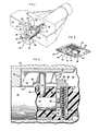
- Fig. 1 is a schematic perspective, partially in phantom, illustrating an embodiment of a reciprocating cylinder lock mechanism in accordance with the present invention;
- Fig. 2 is an enlarged sectional view, taken along line 2-2 of Fig. 1, showing the bolt and keeper portion of the lock mechanism in locked position; and
- Fig. 3 is a schematic perspective, illustrating an embodiment of a keeper structure according to the present invention.
- Referring initially to Fig. 1, there is illustrated an improved reciprocating cylinder lock mechanism in accordance with the present invention and which is useful in an automobile anti-theft security device. The mechanism comprises a
lock casing 20 designed to fit easily under the dashboard of an automobile. However, the shape of the lock casing is not critical and may be appropriately designed to enable use of the lock of the present invention in other devices, e.g., vending machines. - Within
casing 20 is a tubular sleeve 22 having afront sleeve portion 80 with anouter face 33 and a key-receivingnotch 19, and aback sleeve portion 81 withinner face 31. Sleeve 22 is mounted for axial movement in casing 20 from an extended, unlocked position to the retracted, locked position shown in Figs. 1 and 2. Housed within sleeve 22 is arotatable lock shaft 24 having anouter face 35 and a key-receivingnotch 18. A spring 25 (Fig. 1) abutsinner face 31 ofback sleeve portion 81 to normally urge the sleeve into the extended, unlocked position.Outer sleeve face 33 and theouter shaft face 35 are designed to accept insertion of a key intonotches lock shaft 24 to return the mechanism from a locked condition to an unlocked condition. In the unlocked condition,front sleeve portion 80 of sleeve 22 and anouter portion 38 oflock shaft 24 protrude longitudinally outwardly fromface 21 ofcasing 20. Locking can be effected by depressing the protruding portions ofsleeve portion 80 andlock shaft 24 against the urging ofspring 25 untilfaces shaft 24, respectively, are flush withcasing face 21, as will be described subsequently in more detail. - Referring now to Fig. 2,
sleeve portion 81 has an opening orcavity 26 disposed transverse to the axis of sleeve 22 and located close toinner end 50 oflock shaft 24. Withinsleeve cavity 26 is abolt 28 mounted for movement throughcavity 26 along a linear path transverse to the axis of sleeve 22, between a retracted, unlocked position and an extended, locked position (shown in Fig. 2). A spring 30 normally urgesbolt 28 into the extended position but can be compressed to allow retraction of the bolt to an unlocked position. -
Sleeve portion 81 has contiguous therewith asleeve extension 82 which has an external diameter slightly less than the external diameter ofsleeve portion 81, so that theextension 82 may be lapped undersleeve portion 80.Sleeve portion 81 andextension 82 are desirably formed of molded plastic to aid in assembly of the lock mechanism, whilesleeve portion 80 is desirably formed of metal. Connectingsleeve portions rigid pin 90 extending throughsleeve extension 82 and the overlappingsleeve portion 80 and projecting further above sleeve 22. Also extending throughsleeve extension 82 and overlappingsleeve portion 80 is arigid post 84. - A
keeper 36 lies withincasing 20 adjacent to and facing tubular sleeve 22. Different portions ofkeeper 36 engagebolt 28 in its locked and unlocked positions. Referring specifically to Figs. 2 and 3,keeper 36 comprises arectangular attachment portion 70 from which twoidentical flanges channel 87 therebetween. Eachflange 85 forms aperpendicular shoulder surface 53 betweenparallel surfaces flange surface 55 terminates at anedge 58 where it joins asurface 45 which terminates atkeeper attachement portion 70. -
Bolt 28 is a substantially elongated structure having a head portion 62, a shallow lateral recess 32 for cooperation withlock shaft 24, and a longitudinal recess 64 for receiving a spring 30 which urgesbolt 28 towardskeeper 36. Head portion 62 is designed to project into acavity 68 in the casing adjacent to thesurfaces keeper flanges keeper 36 in the locked condition. Head portion 62 comprises a surface 42 parallel to keeper flange surfaces 45, 45.Edge 41 of head 62 is formed by the junction of head surface 42 andhead surface 56 which is parallel to the keeper flange surfaces 55, 55. - Lateral bolt recess 32 is embedded in the bolt side which faces lock shaft
inner end 50 for receiving alock pin 34 extending from lock shaftinner end 50 and eccentrically disposed with respect to the longitudinal axis oflock shaft 24. Longitudinal bolt recess 64 extends intobolt 28 from bolt surface 66 parallel and spaced apart frombolt head surface 56. - When the lock is in an unlocked condition,
front sleeve portion 80 andouter portion 38 ofshaft 24, respectively, protrude from casingface 21. Sleeve 22 andshaft 24 are retained withincasing 20 against the urging ofspring 25 by the engagement of keeper flange shoulder surfaces 53, 53 withedge 41 on the bolt head portion, thereby preventing the sleeve, lock shaft and bolt from being removed from the casing.Post 84 is withinchannel 87 ofkeeper 36, so that sleeve 22 is not rotatable. Spring 30 is compressed by the force exerted by keeper flange surfaces 55, onbolt head surface 56, andlock pin 34, which protrudes into bolt recess 32, is spaced abovelower side 60 of bolt recess 32. - When sleeve
outer face 33 and lock shaftouter face 35 are depressed flush againstcasing face 21, sleeve 22 moves axially inwardly against the urging ofspring 25 untilbolt edge 41 clears keeper flanges edges 58, 58. During this inward movement, post 84 travels withinchannel 87 betweenkeeper flanges Bolt 28 is then urged throughsleeve opening 26 by spring 30, untillower side 60 of bolt recess 32 contacts lock pin 34 (the condition illustrated in both Figs. 1 and 2).Bolt 28 is thereby urged by spring 30 along a linear path through opening 26 in tubular sleeve 22 and intocasing cavity 68 and engagement withkeeper 36. - To return the lock to its unlocked condition, a key is inserted into
outer sleeve face 33 and outerlock shaft face 35. Turning of the key causes lockshaft 24 to rotate approximately 180°. Rotation oflock shaft 24 urges lockpin 34 against bolt recesslower side 60, thereby compressing spring 30 and retractingbolt 28 from its locked position. Whenbolt edge 41 clears keeper edges 58, 58,spring 25 urges sleeve 22 andshaft 24 towardcasing face 21, wherebybolt head surface 56 contacts keeper surfaces 55, 55.Post 84 again travels withinchannel 87 during the outward movement. Once keeper surfaces 55, 55 restrain spring 30 by contact withbolt surface 56, post 84 remaining between the keeper flanges,lock shaft 24 andlock pin 34 rotate 180° back to their original positions, and the lock is returned to unlocked condition. - When the bolt is in either a locked or unlocked position, the engagement between
keeperflanges post 84 andchannel 87 onsleeve portion 80 andkeeper 36, respectively, cooperate to increase the resistance of thesleeve portion 80 to disengagement from its connection withsleeve portion 81 by physical tampering with the lock mechanism. The position of a keeper flange lateral to the post holds sleeve 22 firmly in its non-rotatable position within the lock mechanism of the present invention by impeding lateral rotation ofsleeve portion 80. - The position of each
flange sleeve portion 80 in either direction, because assleeve portion 80 is twisted slightly in one direction, post 84 will meet a flange and be prevented from further movement in that direction. Attempts to twist the sleeve in the opposite direction will cause the post to meet the other flange. Thus, physical tampering with the lock mechanism without a key can be defeated to a considerable extent. When in a locked or unlocked position, sleeve 22 is resistant to any force applied to laterally rotatesleeve portion 80 in an effort to destroy the interconnection betweensleeve portion 80 andsleeve portion 81, thereby preventing removal ofsleeve portion 80 and easy access to the bolt. This improvement in the lock mechanism therefore enables the lock to defeat a frequently used method of tampering with reciprocating cylinder lock mechanisms.
Claims (5)
Priority Applications (1)
| Application Number | Priority Date | Filing Date | Title |
|---|---|---|---|
| AT85104893T ATE35439T1 (en) | 1984-07-02 | 1985-04-22 | LOCK PROTECTED AGAINST UNAUTHORIZED MANIPULATION. |
Applications Claiming Priority (2)
| Application Number | Priority Date | Filing Date | Title |
|---|---|---|---|
| US627077 | 1984-07-02 | ||
| US06/627,077 US4611477A (en) | 1984-07-02 | 1984-07-02 | Tamper resistant lock bolt assembly |
Publications (2)
| Publication Number | Publication Date |
|---|---|
| EP0166891A1 EP0166891A1 (en) | 1986-01-08 |
| EP0166891B1 true EP0166891B1 (en) | 1988-06-29 |
Family
ID=24513096
Family Applications (1)
| Application Number | Title | Priority Date | Filing Date |
|---|---|---|---|
| EP85104893A Expired EP0166891B1 (en) | 1984-07-02 | 1985-04-22 | Improved tamper resistant lock bolt assembly |
Country Status (4)
| Country | Link |
|---|---|
| US (1) | US4611477A (en) |
| EP (1) | EP0166891B1 (en) |
| AT (1) | ATE35439T1 (en) |
| DE (1) | DE3563549D1 (en) |
Families Citing this family (11)
| Publication number | Priority date | Publication date | Assignee | Title |
|---|---|---|---|---|
| US4760721A (en) * | 1986-01-27 | 1988-08-02 | Chicago Lock Company | Handle flange assembly |
| US5171155A (en) * | 1991-09-03 | 1992-12-15 | Humberto Mendoza | Safety lock for electrical appliance plugs |
| US5297404A (en) * | 1992-07-06 | 1994-03-29 | Hsl Marketing, Inc. | Bolt for an inner cylinder lock |
| US5255544A (en) * | 1992-10-26 | 1993-10-26 | Wu Wen Yin | Housing for a lock in an automobile steering lock |
| ES2154538B1 (en) * | 1998-03-04 | 2001-09-01 | Talleres Escoriaza Sa | EXTRAIBLE COMBINATION CYLINDER FROM THE OUTSIDE FOR LOCK |
| US6223570B1 (en) * | 2000-05-04 | 2001-05-01 | Tian-Yuan Chen | Housing for an automobile steering wheel lock |
| US6564597B1 (en) | 2000-08-14 | 2003-05-20 | Star Lock Systems, Inc. | Vandal resistant T-handle assembly |
| US6832499B2 (en) | 2000-08-14 | 2004-12-21 | Star Lock Systems, Inc. | Vandal resistant T-handle assembly |
| US7617708B2 (en) * | 2006-07-28 | 2009-11-17 | Volkswagen Ag | Ignition lock for a motor vehicle and method of operating an ignition lock system |
| WO2009076167A2 (en) * | 2007-12-05 | 2009-06-18 | Lifelong Locks, Llc | Cam pin stop apparatus |
| US9428936B2 (en) * | 2010-09-09 | 2016-08-30 | Valeo Securite Habitacle | Lock for a motor vehicle lock system |
Family Cites Families (4)
| Publication number | Priority date | Publication date | Assignee | Title |
|---|---|---|---|---|
| US3538725A (en) * | 1968-10-31 | 1970-11-10 | Cfc Enterprises | Hood locking device |
| US3921422A (en) * | 1973-10-04 | 1975-11-25 | Bmr Security Prod Corp | Locking bar system |
| US4083211A (en) * | 1977-04-18 | 1978-04-11 | Chicago Lock Co. | Axial split-pin tumbler-type lock mechanism for a handle lock |
| US4380915A (en) * | 1981-04-06 | 1983-04-26 | The Eastern Company | Latch having a removable lock |
-
1984
- 1984-07-02 US US06/627,077 patent/US4611477A/en not_active Expired - Fee Related
-
1985
- 1985-04-22 DE DE8585104893T patent/DE3563549D1/en not_active Expired
- 1985-04-22 EP EP85104893A patent/EP0166891B1/en not_active Expired
- 1985-04-22 AT AT85104893T patent/ATE35439T1/en not_active IP Right Cessation
Also Published As
| Publication number | Publication date |
|---|---|
| ATE35439T1 (en) | 1988-07-15 |
| US4611477A (en) | 1986-09-16 |
| DE3563549D1 (en) | 1988-08-04 |
| EP0166891A1 (en) | 1986-01-08 |
Similar Documents
| Publication | Publication Date | Title |
|---|---|---|
| US4074548A (en) | Lock cylinder assembly | |
| CN1075588C (en) | Locking device containing cylinder lock with main execution locking function for vehicle | |
| US5704234A (en) | Cylinder lock incorporating a slam resistance pad | |
| US6546768B1 (en) | Ignition lock system for motor vehicles | |
| US4611477A (en) | Tamper resistant lock bolt assembly | |
| US5212972A (en) | Tamper resistant pop-handle lock | |
| US3919867A (en) | Anti-theft safety lock device with means preventing its unallowed removal from the lock-holder | |
| EP0675248A1 (en) | Cylinder lock device resistible against unauthorized unlocking | |
| US3721112A (en) | Locks | |
| US4143528A (en) | Anti-theft locking devices | |
| US6202453B1 (en) | Trailer guard | |
| US4760721A (en) | Handle flange assembly | |
| US5720191A (en) | Padlock | |
| US4074547A (en) | Lock cylinder assembly | |
| US3722243A (en) | Steering lock for motor vehicles | |
| JP3150816B2 (en) | Cylinder lock | |
| EP0049050B1 (en) | Cylinder lock | |
| US4056955A (en) | Ignition lock | |
| US4788839A (en) | Tamper resistant lock bolt assembly | |
| KR20060096301A (en) | Magnetic card-type cylinder correcting device having the function of preventing shock release or breaking | |
| US3484569A (en) | Reminder auto ignition switch | |
| US1705363A (en) | Lock | |
| US5709115A (en) | Sidebar ignition lock | |
| EP0983880A1 (en) | Trailer coupling with lock | |
| JPH086513B2 (en) | Sidebar lock device |
Legal Events
| Date | Code | Title | Description |
|---|---|---|---|
| PUAI | Public reference made under article 153(3) epc to a published international application that has entered the european phase |
Free format text: ORIGINAL CODE: 0009012 |
|
| AK | Designated contracting states |
Designated state(s): AT BE CH DE FR GB IT LI LU NL SE |
|
| 17P | Request for examination filed |
Effective date: 19860620 |
|
| 17Q | First examination report despatched |
Effective date: 19861211 |
|
| RAP1 | Party data changed (applicant data changed or rights of an application transferred) |
Owner name: CHAPMAN INDUSTRIES CORP. |
|
| GRAA | (expected) grant |
Free format text: ORIGINAL CODE: 0009210 |
|
| AK | Designated contracting states |
Kind code of ref document: B1 Designated state(s): AT BE CH DE FR GB IT LI LU NL SE |
|
| PG25 | Lapsed in a contracting state [announced via postgrant information from national office to epo] |
Ref country code: NL Effective date: 19880629 Ref country code: LI Effective date: 19880629 Ref country code: IT Free format text: LAPSE BECAUSE OF FAILURE TO SUBMIT A TRANSLATION OF THE DESCRIPTION OR TO PAY THE FEE WITHIN THE PRESCRIBED TIME-LIMIT;WARNING: LAPSES OF ITALIAN PATENTS WITH EFFECTIVE DATE BEFORE 2007 MAY HAVE OCCURRED AT ANY TIME BEFORE 2007. THE CORRECT EFFECTIVE DATE MAY BE DIFFERENT FROM THE ONE RECORDED. Effective date: 19880629 Ref country code: FR Free format text: THE PATENT HAS BEEN ANNULLED BY A DECISION OF A NATIONAL AUTHORITY Effective date: 19880629 Ref country code: CH Effective date: 19880629 Ref country code: BE Effective date: 19880629 Ref country code: AT Effective date: 19880629 |
|
| REF | Corresponds to: |
Ref document number: 35439 Country of ref document: AT Date of ref document: 19880715 Kind code of ref document: T |
|
| PG25 | Lapsed in a contracting state [announced via postgrant information from national office to epo] |
Ref country code: SE Effective date: 19880630 |
|
| REF | Corresponds to: |
Ref document number: 3563549 Country of ref document: DE Date of ref document: 19880804 |
|
| REG | Reference to a national code |
Ref country code: CH Ref legal event code: PL |
|
| NLV1 | Nl: lapsed or annulled due to failure to fulfill the requirements of art. 29p and 29m of the patents act | ||
| EN | Fr: translation not filed | ||
| PLBE | No opposition filed within time limit |
Free format text: ORIGINAL CODE: 0009261 |
|
| STAA | Information on the status of an ep patent application or granted ep patent |
Free format text: STATUS: NO OPPOSITION FILED WITHIN TIME LIMIT |
|
| PG25 | Lapsed in a contracting state [announced via postgrant information from national office to epo] |
Ref country code: LU Free format text: LAPSE BECAUSE OF NON-PAYMENT OF DUE FEES Effective date: 19890430 |
|
| 26N | No opposition filed | ||
| PG25 | Lapsed in a contracting state [announced via postgrant information from national office to epo] |
Ref country code: DE Effective date: 19900103 |
|
| PGFP | Annual fee paid to national office [announced via postgrant information from national office to epo] |
Ref country code: GB Payment date: 19900331 Year of fee payment: 6 |
|
| REG | Reference to a national code |
Ref country code: GB Ref legal event code: 732 |
|
| PG25 | Lapsed in a contracting state [announced via postgrant information from national office to epo] |
Ref country code: GB Effective date: 19910422 |
|
| GBPC | Gb: european patent ceased through non-payment of renewal fee |