EP0166552B1 - Extended surface apparatus for use in dispensing liquids - Google Patents
Extended surface apparatus for use in dispensing liquids Download PDFInfo
- Publication number
- EP0166552B1 EP0166552B1 EP85304122A EP85304122A EP0166552B1 EP 0166552 B1 EP0166552 B1 EP 0166552B1 EP 85304122 A EP85304122 A EP 85304122A EP 85304122 A EP85304122 A EP 85304122A EP 0166552 B1 EP0166552 B1 EP 0166552B1
- Authority
- EP
- European Patent Office
- Prior art keywords
- elements
- liquid
- extended surface
- nozzle assembly
- communication means
- Prior art date
- Legal status (The legal status is an assumption and is not a legal conclusion. Google has not performed a legal analysis and makes no representation as to the accuracy of the status listed.)
- Expired
Links
- 239000007788 liquid Substances 0.000 title claims description 68
- 238000003491 array Methods 0.000 claims description 10
- 230000000717 retained effect Effects 0.000 claims description 7
- 230000002745 absorbent Effects 0.000 claims description 4
- 239000002250 absorbent Substances 0.000 claims description 4
- 238000000034 method Methods 0.000 claims description 3
- 239000003814 drug Substances 0.000 description 14
- 230000000694 effects Effects 0.000 description 4
- 239000000463 material Substances 0.000 description 4
- 239000000443 aerosol Substances 0.000 description 3
- 230000001419 dependent effect Effects 0.000 description 3
- 239000006260 foam Substances 0.000 description 3
- 239000004033 plastic Substances 0.000 description 3
- 229920003023 plastic Polymers 0.000 description 3
- 235000017166 Bambusa arundinacea Nutrition 0.000 description 2
- 235000017491 Bambusa tulda Nutrition 0.000 description 2
- 241001330002 Bambuseae Species 0.000 description 2
- 235000015334 Phyllostachys viridis Nutrition 0.000 description 2
- 239000011425 bamboo Substances 0.000 description 2
- 239000006196 drop Substances 0.000 description 2
- 239000012530 fluid Substances 0.000 description 2
- 230000001788 irregular Effects 0.000 description 2
- 239000007922 nasal spray Substances 0.000 description 2
- 229940097496 nasal spray Drugs 0.000 description 2
- 239000003380 propellant Substances 0.000 description 2
- 239000000853 adhesive Substances 0.000 description 1
- 230000001070 adhesive effect Effects 0.000 description 1
- 150000001768 cations Chemical class 0.000 description 1
- 238000004140 cleaning Methods 0.000 description 1
- 239000003889 eye drop Substances 0.000 description 1
- 238000005187 foaming Methods 0.000 description 1
- 230000005484 gravity Effects 0.000 description 1
- 238000007654 immersion Methods 0.000 description 1
- 230000014759 maintenance of location Effects 0.000 description 1
- 238000004519 manufacturing process Methods 0.000 description 1
- 230000002093 peripheral effect Effects 0.000 description 1
- 239000008194 pharmaceutical composition Substances 0.000 description 1
- 239000012858 resilient material Substances 0.000 description 1
- 239000007921 spray Substances 0.000 description 1
- 239000000126 substance Substances 0.000 description 1
Images


Classifications
-
- G—PHYSICS
- G01—MEASURING; TESTING
- G01F—MEASURING VOLUME, VOLUME FLOW, MASS FLOW OR LIQUID LEVEL; METERING BY VOLUME
- G01F11/00—Apparatus requiring external operation adapted at each repeated and identical operation to measure and separate a predetermined volume of fluid or fluent solid material from a supply or container, without regard to weight, and to deliver it
-
- B—PERFORMING OPERATIONS; TRANSPORTING
- B65—CONVEYING; PACKING; STORING; HANDLING THIN OR FILAMENTARY MATERIAL
- B65D—CONTAINERS FOR STORAGE OR TRANSPORT OF ARTICLES OR MATERIALS, e.g. BAGS, BARRELS, BOTTLES, BOXES, CANS, CARTONS, CRATES, DRUMS, JARS, TANKS, HOPPERS, FORWARDING CONTAINERS; ACCESSORIES, CLOSURES, OR FITTINGS THEREFOR; PACKAGING ELEMENTS; PACKAGES
- B65D83/00—Containers or packages with special means for dispensing contents
Definitions
- the present invention relates to dispensing devices and specifically to such devices which are commonly used to dispense a definite quantity of a liquid such as "eye drop” or "nasal spray".
- dispensers have been objectionable for a number of reasons.
- the majority of dispensers comprise a resilient container and nozzle, sometimes with a tube connecting the nozzle with the contents of the container.
- a tube connecting the nozzle with the contents of the container.
- capillary systems comprise, for example, a piece of bamboo cane which is inherently irregular in nature and not well adapted to use in the mass production of large numbers of dispensing devices each able to dispense a predetermined quantity of liquid. Also, irregular sized drops of the liquid are able to cling to the bamboo and are dispensed in addition to the predetermiend quantity. This affects the accuracy of such dispensers.
- Alternative known dispensers comprise a pressurized vessel having a valve through which liquids may be forced in the form of spray by a propellant. Risk is involved in using such dispensers in that propellant such as Freon may enter the human body. Furthermore, such dispensers require a container able to withstand high pressures and a complex valve. These features add to the expense of the dispensers.
- U.S. Specification No. 4027789 discloses a foaming device for generating and dispensing foams formed by mixing a gas with a foamable liquid.
- British Specification No. 1478607 discloses a foam dispenser which is capable of generating and dispensing foam in an upright or an inverted position.
- the present invention provides an apparatus for use in a vessel for dispensing a liquid, comprising a nozzle assembly and an extended surface apparatus connected to the nozzle assembly, the extended surface apparatus comprising an array or arrays of spaced apart elements and communication means connecting said array or arrays and said nozzle assembly, characterised in that the elements are arranged such that, in use of the apparatus, they can be charged with the retain a predetermined dose of the liquid, utilising intermolecular attraction between said liquid and said elements, by means of the elements being brought into contact with and then removed from the body of liquid in the vessel, and the said liquid can be delivered from the elements to the nozzle assembly via the said communication means, whereby the apparatus can, in use, deliver a predetermined dosage of liquid.
- the extended surface apparatus may comprise an annular array of circumferentially spaced apart elements.
- the elements of the extended surface apparatus may be connected with said nozzle assembly by a communication means, one end of which opens into a central passage defined by said annular array of elements.
- the elements may be fixed to a flared skirt projecting from said one end of said communication means.
- the array of elements may comprise a plurality of long elements interleaved with shorter elements.
- the extended surface apparatus may include a radially extending disk supported by the said elements, and from which extend a further array of elements.
- the elements may be tapered.
- the apparatus may include a gravitationally sealed one-way valve controlling flow along said communication means.
- the one-way valve may comprise a ball entrapped by said elements, and adapted to seal against one end of said communi-. cation means.
- the extended surface apparatus is contained within the nozzle assembly of the vessel.
- the apparatus may then include an absorbent pad disposed adjacent to said array of elements.
- the apparatus may include an air-duct through which air may pass from the interior of said vessel to mix with said dose of liquid, prior to explusion from said vessel.
- a further absorbent pad may be disposed adjacent the opening, within the dispenser, of said air-duct.
- the extended surface apparatus includes an upturned cup having a plurality of slots disposed in a radial array around said cup, and an annular array of spaced apart elements disposed within and supported by said cup.
- the extended surface apparatus may then comprise a communication means having a first end disposed within a passage defined by said annular array of elements and a second end connected with said nozzle assembly.
- the extended surface apparatus is made of a plastics material with the vessel being of a resilient plastics material.
- the vessel can also be comprised of numerous other resilient materials.
- the spaced apart elements can be arranged in a configuration which, during the dispensing of the measured dose of liquid, creates a vortex effect in the liquid as it passes from the elements to the exit of the nozzle via the communication means.
- the elements may be radially disposed and curvedly shaped.
- the present invention does not rely on the capillary effects, and has the advantage that the extended surface apparatus can be contacted completely with the liquid, as the liquid can charge from many directions with the air easily being replaced by the liquid.
- the present invention further provides a method of dispensing a predetermined dosage of a liquid from a collapsible vessel containing a liquid and including an apparatus comprising a nozzle assembly and an extended surface apparatus connected to the nozzle assembly, the extended surface apparatus comprising an array or arrays of spaced apart elements and communication means connecting said array or arrays and said nozzle assembly, wherein the elements are brought into contact with and then removed from the liquid in the vessel, a predetermined dose of the liquid being retained on the elements utilising intermolecular attraction between the said liquid and the said elements, and expelling a predetermined dosage of liquid through the nozzle assembly by forcing air across the elements so that liquid retained on the elements is conveyed via the communication means to the nozzle assembly.
- a nozzle assembly 1 has a peripheral flange 2 adapted to be fitted within the neck of a dispensing vessel in an air tight manner.
- Such vessels are well known and are generally manufactured from resilient plastics material. However, they may comprise, for example, a pressurized container.
- the nozzle assembly 1 also has a blind bore 3 having a plurality of slots 4.
- the blind bore 3 terminates in a wall 5 which is pierced by a jet 6.
- An extended surface apparatus 7 comprises a communication means 8 having a first end 9 adapted to be homed within bore 3 and a second end furnished with a flared skirt 10.
- a plurality of elements 11 are fixedly attached to the lower side of skirt 10, and project downwardly therefrom, when the dispenser is in an upstanding position.
- the elements 11 are arranged in an annular. array, as is indicated in Fig. 3. Some of the elements 11 are longer than others and may be of varying widths: the width of any given element may change along the length of the element and/ or some elements may be wider than others.
- the array of elements 11 define a central passage 12.
- the passage 12 is substantially coaxial with the communication means 8.
- the elements such as those which are shown in Fig. 3 can be configured and arranged in such a way that a vortex can be created during dispensing as the liquid passes along the communication means.
- This effect is created by placing the elements radially relative to the central axis of the communication means, each of said elements being curvedly shaped such that the plane in which the radii of the curved elements are located is substantially normal to the central axis of the communication means. This creates a vortex in the liquid as the liquid is imparted from the elements to the nozzle via the central passage 12.
- a nozzle extension piece 13 is snap lockingly engageable with the nozzle assembly 1, and is able to be removed from the nozzle assembly for cleaning.
- the vessel is partially filled with the liquid which is to be dispensed for example, a medicament.
- the extended surface apparatus 7 of the present invention must be immersed in the liquid such that the elements are submerged. This can be done for example by inverting the dispenser such that the liquid, assisted by gravity, moves towards the nozzle of the dispenser. Immersion of the extended surface elements can also be achieved by shaking the dispenser.
- the solid-liquid intermolecular attraction takes place with the result that a predetermined dose of the liquid is retained on and between the elements.
- the total surface area of the elements comes in contact with the liquid almost at once, thus obviating the need for reliance on any capillary action to achieve the desired result.
- the volume of the liquid retained by intermolecular attraction is dependent upon the size, thickness and number of the elements 11 in the array or arrays of elements. It is also dependent upon the spacing and surface area of contact between the liquid and the elements, along with the surface properties of the material used to form the elements with respect to the liquid.
- the dispensing process is activated when the container is squeezed, effectively increasing the pressure within the container. This increase in pressure, which is evenly distributed throughout the inside of the container, forces air across the elements holding the medicament which is then expressed through the communication means 8 and from jet nozzle 6. Simultaneously, air from within the container is forced through grooves 4 and mixes with the medicament being forced through the communication means 8, resulting in an aerosol being expressed through jet 6.
- the quantity of medicament to be expressed is dependent upon and can be varied by varying for instance, the size of the elements, the number of elements in the array or the thickness of each of the elements.
- Elements 11 are shaped as shown in Fig. 2 in order to dislodge an excess drop which may otherwise cling to the lower end of the elements.
- the longer elements which project beyond the shorter elements effectively provide an area of reduced molecular attraction due to the reduced number and/or greater spacing of the elements and due to their reduced size. If a droplet of medicament of too large a proportion is attached to the elements, the excess will be shed as a result of the abovementioned reduced cohesive forces at the lower end of the extended surface element, thus manifesting a significant advantage over the capillary devices.
- FIG. 5 an extended surface apparatus similar to that of Fig. 2 is shown but in this instance the elements 11 support a substantially horizontally extending disk 14 below which hang a number of elements 11a.
- the purpose of the disk 14 and the elements 11a is to provide an apparatus able to repetitively hold a constant quantity of medicament. If the quantity is too large, a portion of it will overhang the disk 14 and contact one of the lower elements 11 a thus isolating it from the medicament to be expressed. Elements 11 a can be different in number from elements 11.
- FIG. 6 an alternate nozzle assembly 15 and alternate extended surface apparatus 16 are shown.
- the extended surface apparatus 16 operates in a manner similar to that described above but without the elements 11 a and also without the grooves to provide the aerosol effect.
- Fig. 7 shows another extended surface apparatus 17 similar to that shown in Fig. 6 but including a ball 18 which, when the dispenser is upturned, seals communication means 19 at 20, preventing medicament from seeping from the dispenser.
- nozzle assembly 24 shown in Fig. 8 is adapted for dispensing, for example, inhalant.
- the dispenser having nozzle assembly 24 operates in the same manner as previously described dispensers.
- the extended surface apparatus 7 of Fig. 8 is identical to that shown in Fig. 2.
- Figs. 9 and 10 show yet another assembly and extended surface apparatus, suitable for dispensing a medicament into another container.
- the extended surface apparatus in this case. includes an upturned cup-like element 27 having a plurality of slots as is indicated at 28 and containing a radial array or arrays of elements 29.
- a communication means 30 has one end disposed within the cup-like element 27, centrally with respect to elements 29. The other end of tube 30 projects from the dispenser.
- Fig. 11 shows a dispenser similar in most respects to those above described but adapted to be used in the upturned position.
- An extended surface apparatus 31 is, when the vessel is in the upright position, immersed in medicament stored in vessel 32. When the dispenser is upturned, the extended surface apparatus 31 is emerged from the medicament and holds a quantity of the medicament which will be expelled when the dispenser is squeezed.
- a further nozzle assembly comprising an array of elements 33 located adjacent to fluid duct 34.
- An air duct 35 joins fluid duct 34 at 36 in order to create an aerosol and is open to an access port 37 within the nozzle assembly.
- Pad elements 38 surround both the elements 33 and the port 37. These elements are adapted to draw away any excess droplets of medicament from the elements and from the passage so that when the dispenser is squeezed only medicament attached to the element is expressed from the nozzle.
- extended surface is intended to describe surfaces which extend from the communication means.
- the length of the extension is one factor which controls the measured dose of the liquid because, as the elements are extended further, their surface area increases altering the amount of liquid which will adhere to the surface.
- the dose of liquid to be dispensed can be controlled by varying the degree of extension of the elements.
- the versatility of an extended surface in altering the measured dose distinguishes it from a surface which is not extended. By having the surfaces extended, relatively large surface areas can be achieved with economy of space.
- the communication means used in accordance with the invention need not necessarily, of course, be a tube. All that is necessary is that when installed in a vessel the extended surface apparatus be maintained in such a position relative to an opening in the vessel (e.g. the nozzle opening) that if air or other gas is forced out of the vessel through the opening at least some of the air or other gas passes over the spaced apart elements. It will of course be understood that at the dispensing stage the elements are in a gaseous, not a liquid, medium.
- the spacing between the elements is significant because the volume held between the elements can be controlled by the spacing. Thus, the greater the spacing the heavier the liquid which can be retained between the elements.
Landscapes
- Physics & Mathematics (AREA)
- Fluid Mechanics (AREA)
- General Physics & Mathematics (AREA)
- Engineering & Computer Science (AREA)
- Mechanical Engineering (AREA)
- Containers And Packaging Bodies Having A Special Means To Remove Contents (AREA)
- Nozzles (AREA)
Description
- The present invention relates to dispensing devices and specifically to such devices which are commonly used to dispense a definite quantity of a liquid such as "eye drop" or "nasal spray".
- Hitherto, dispensing devices have been objectionable for a number of reasons. The majority of dispensers comprise a resilient container and nozzle, sometimes with a tube connecting the nozzle with the contents of the container. Upon squeezing the container, maybe after inverting it, and then squeezing it, an indeterminate quantity of the liquid contents is expressed from the container. When the substance is a pharmaceutical composition, it may be undesirable to dispence more or less than a predetermined dose.
- It is known to provide a capillary system within the dispensers which, when the dispenser is upturned, absorbs a quantity of the liquid contents to be dispensed. However, known capillary systems comprise, for example, a piece of bamboo cane which is inherently irregular in nature and not well adapted to use in the mass production of large numbers of dispensing devices each able to dispense a predetermined quantity of liquid. Also, irregular sized drops of the liquid are able to cling to the bamboo and are dispensed in addition to the predetermiend quantity. This affects the accuracy of such dispensers.
- Alternative known dispensers comprise a pressurized vessel having a valve through which liquids may be forced in the form of spray by a propellant. Risk is involved in using such dispensers in that propellant such as Freon may enter the human body. Furthermore, such dispensers require a container able to withstand high pressures and a complex valve. These features add to the expense of the dispensers.
- It is an object of the present invention to overcome or at least ameliorate the above-mentioned shortcomings of the prior art by simple means.
- U.S. Specification No. 4027789 discloses a foaming device for generating and dispensing foams formed by mixing a gas with a foamable liquid. British Specification No. 1478607 discloses a foam dispenser which is capable of generating and dispensing foam in an upright or an inverted position.
- The present invention provides an apparatus for use in a vessel for dispensing a liquid, comprising a nozzle assembly and an extended surface apparatus connected to the nozzle assembly, the extended surface apparatus comprising an array or arrays of spaced apart elements and communication means connecting said array or arrays and said nozzle assembly, characterised in that the elements are arranged such that, in use of the apparatus, they can be charged with the retain a predetermined dose of the liquid, utilising intermolecular attraction between said liquid and said elements, by means of the elements being brought into contact with and then removed from the body of liquid in the vessel, and the said liquid can be delivered from the elements to the nozzle assembly via the said communication means, whereby the apparatus can, in use, deliver a predetermined dosage of liquid.
- The extended surface apparatus may comprise an annular array of circumferentially spaced apart elements. The elements of the extended surface apparatus may be connected with said nozzle assembly by a communication means, one end of which opens into a central passage defined by said annular array of elements. The elements may be fixed to a flared skirt projecting from said one end of said communication means. The array of elements may comprise a plurality of long elements interleaved with shorter elements. The extended surface apparatus may include a radially extending disk supported by the said elements, and from which extend a further array of elements. The elements may be tapered. The apparatus may include a gravitationally sealed one-way valve controlling flow along said communication means. The one-way valve may comprise a ball entrapped by said elements, and adapted to seal against one end of said communi-. cation means.
- In one embodiment of the invention, the extended surface apparatus is contained within the nozzle assembly of the vessel. The apparatus may then include an absorbent pad disposed adjacent to said array of elements. The apparatus may include an air-duct through which air may pass from the interior of said vessel to mix with said dose of liquid, prior to explusion from said vessel. A further absorbent pad may be disposed adjacent the opening, within the dispenser, of said air-duct.
- In another embodiment of the invention the extended surface apparatus includes an upturned cup having a plurality of slots disposed in a radial array around said cup, and an annular array of spaced apart elements disposed within and supported by said cup. The extended surface apparatus may then comprise a communication means having a first end disposed within a passage defined by said annular array of elements and a second end connected with said nozzle assembly.
- In a preferred embodiment the extended surface apparatus is made of a plastics material with the vessel being of a resilient plastics material.
- The vessel can also be comprised of numerous other resilient materials.
- In another embodiment the spaced apart elements can be arranged in a configuration which, during the dispensing of the measured dose of liquid, creates a vortex effect in the liquid as it passes from the elements to the exit of the nozzle via the communication means. For example, the elements may be radially disposed and curvedly shaped.
- It is an advantage of the present invention over the previously known capillary devices that an accurate dosage of the liquid to be dispensed can be achieved. The present invention does not rely on the capillary effects, and has the advantage that the extended surface apparatus can be contacted completely with the liquid, as the liquid can charge from many directions with the air easily being replaced by the liquid.
- In the capillary system adhesive surface tension forces create a reasonably large resistance to the air and liquid stream resulting in the liquid not being completely expressed.
- The present invention further provides a method of dispensing a predetermined dosage of a liquid from a collapsible vessel containing a liquid and including an apparatus comprising a nozzle assembly and an extended surface apparatus connected to the nozzle assembly, the extended surface apparatus comprising an array or arrays of spaced apart elements and communication means connecting said array or arrays and said nozzle assembly, wherein the elements are brought into contact with and then removed from the liquid in the vessel, a predetermined dose of the liquid being retained on the elements utilising intermolecular attraction between the said liquid and the said elements, and expelling a predetermined dosage of liquid through the nozzle assembly by forcing air across the elements so that liquid retained on the elements is conveyed via the communication means to the nozzle assembly.
- Preferred embodiments of the present invention will now be described by way of non-limiting example only, with reference to the accompanying drawings in which:
- Fig. 1 is a cross-sectional side elevation of the nozzle and extended surface apparatus of a dispensing vessel according to the present invention.
- Fig. 2 is a side elevation of the extended surface apparatus shown in Fig. 1.
- Fig. 3 is a schematic underview of the extended surface apparatus of Fig. 2 showing a configuration of the elements according to one embodiment of the present invention.
- Fig. 4 is a cross-sectional view taken on line 4-4 of Fig. 1.
- Fig. 5 is a side elevation of an extended surface apparatus including an additional drip-plate.
- Fig. 6 is a cross-sectional side elevation of a nozzle and extended surface apparatus of a second embodiment of the present invention.
- Fig. 7 is a cross-sectional side elevation of an extended surface apparatus of a third embodiment of the present invention.
- Fig. 8 is a cross-sectional side elevation of an alternative nozzle and an extended surface apparatus shown in Fig. 1.
- Fig. 9 is a cross-sectional side elevation of yet another alternative nozzle and an extended surface apparatus of a further embodiment of the present invention.
- Fig. 10 is a cross-sectional view taken on line 10-10 of Fig. 9.
- Fig. 11 is a cross-sectional side elevation of a dispenser according to a further embodiment of the present invention.
- Fig. 12 is a cross-sectional side elevation of a nozzle and extended surface apparatus of another embodiment of the present invention.
- Fig. 13 is a cross-sectional view taken on line 13-13 of Fig. 12, and
- Fig. 14 is a cross-sectional view taken on line 14-14 of Fig. 12.
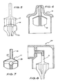
- Referring first to Figs. 1, 2, 3 and 4, a
nozzle assembly 1 has aperipheral flange 2 adapted to be fitted within the neck of a dispensing vessel in an air tight manner. Such vessels are well known and are generally manufactured from resilient plastics material. However, they may comprise, for example, a pressurized container. - The
nozzle assembly 1 also has ablind bore 3 having a plurality ofslots 4. Theblind bore 3 terminates in awall 5 which is pierced by ajet 6. - An extended
surface apparatus 7 comprises a communication means 8 having afirst end 9 adapted to be homed withinbore 3 and a second end furnished with a flaredskirt 10. A plurality ofelements 11 are fixedly attached to the lower side ofskirt 10, and project downwardly therefrom, when the dispenser is in an upstanding position. - The
elements 11 are arranged in an annular. array, as is indicated in Fig. 3. Some of theelements 11 are longer than others and may be of varying widths: the width of any given element may change along the length of the element and/ or some elements may be wider than others. The array ofelements 11 define acentral passage 12. Thepassage 12 is substantially coaxial with the communication means 8. - Alternatively, the elements such as those which are shown in Fig. 3 can be configured and arranged in such a way that a vortex can be created during dispensing as the liquid passes along the communication means.
- This effect is created by placing the elements radially relative to the central axis of the communication means, each of said elements being curvedly shaped such that the plane in which the radii of the curved elements are located is substantially normal to the central axis of the communication means. This creates a vortex in the liquid as the liquid is imparted from the elements to the nozzle via the
central passage 12. - A
nozzle extension piece 13 is snap lockingly engageable with thenozzle assembly 1, and is able to be removed from the nozzle assembly for cleaning. - In operation, the vessel is partially filled with the liquid which is to be dispensed for example, a medicament.
- The
extended surface apparatus 7 of the present invention must be immersed in the liquid such that the elements are submerged. This can be done for example by inverting the dispenser such that the liquid, assisted by gravity, moves towards the nozzle of the dispenser. Immersion of the extended surface elements can also be achieved by shaking the dispenser. - Once the contact takes place between the liquid and the
extended surface apparatus 7 of the present invention and in particular with theelements 11 of the said apparatus, the solid-liquid intermolecular attraction takes place with the result that a predetermined dose of the liquid is retained on and between the elements. - The total surface area of the elements comes in contact with the liquid almost at once, thus obviating the need for reliance on any capillary action to achieve the desired result.
- The volume of the liquid retained by intermolecular attraction is dependent upon the size, thickness and number of the
elements 11 in the array or arrays of elements. It is also dependent upon the spacing and surface area of contact between the liquid and the elements, along with the surface properties of the material used to form the elements with respect to the liquid. - In the embodiment shown in Fig. 2 the retention of the liquid by the elements is assisted by the
skirt 10 due to the intermolecular attraction between the skirt and the liquid. - The dispensing process is activated when the container is squeezed, effectively increasing the pressure within the container. This increase in pressure, which is evenly distributed throughout the inside of the container, forces air across the elements holding the medicament which is then expressed through the communication means 8 and from
jet nozzle 6. Simultaneously, air from within the container is forced throughgrooves 4 and mixes with the medicament being forced through the communication means 8, resulting in an aerosol being expressed throughjet 6. - The quantity of medicament to be expressed is dependent upon and can be varied by varying for instance, the size of the elements, the number of elements in the array or the thickness of each of the elements.
-
Elements 11 are shaped as shown in Fig. 2 in order to dislodge an excess drop which may otherwise cling to the lower end of the elements. The longer elements which project beyond the shorter elements effectively provide an area of reduced molecular attraction due to the reduced number and/or greater spacing of the elements and due to their reduced size. If a droplet of medicament of too large a proportion is attached to the elements, the excess will be shed as a result of the abovementioned reduced cohesive forces at the lower end of the extended surface element, thus manifesting a significant advantage over the capillary devices. - Referring now to Fig. 5, an extended surface apparatus similar to that of Fig. 2 is shown but in this instance the
elements 11 support a substantially horizontally extendingdisk 14 below which hang a number ofelements 11a. - The purpose of the
disk 14 and theelements 11a, is to provide an apparatus able to repetitively hold a constant quantity of medicament. If the quantity is too large, a portion of it will overhang thedisk 14 and contact one of thelower elements 11 a thus isolating it from the medicament to be expressed.Elements 11 a can be different in number fromelements 11. - Referring now to Fig. 6, an
alternate nozzle assembly 15 and alternateextended surface apparatus 16 are shown. Theextended surface apparatus 16 operates in a manner similar to that described above but without theelements 11 a and also without the grooves to provide the aerosol effect. - Fig. 7 shows another
extended surface apparatus 17 similar to that shown in Fig. 6 but including a ball 18 which, when the dispenser is upturned, seals communication means 19 at 20, preventing medicament from seeping from the dispenser. - It will be appreciated that the dispensers of the prior described embodiments are suitable for dispensing nasal spray. However,
nozzle assembly 24 shown in Fig. 8 is adapted for dispensing, for example, inhalant. The dispenser havingnozzle assembly 24 operates in the same manner as previously described dispensers. Theextended surface apparatus 7 of Fig. 8 is identical to that shown in Fig. 2. - Figs. 9 and 10 show yet another assembly and extended surface apparatus, suitable for dispensing a medicament into another container.
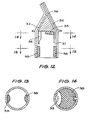
- The extended surface apparatus in this case. includes an upturned cup-
like element 27 having a plurality of slots as is indicated at 28 and containing a radial array or arrays ofelements 29. A communication means 30 has one end disposed within the cup-like element 27, centrally with respect toelements 29. The other end oftube 30 projects from the dispenser. - Fig. 11 shows a dispenser similar in most respects to those above described but adapted to be used in the upturned position.
- An
extended surface apparatus 31 is, when the vessel is in the upright position, immersed in medicament stored invessel 32. When the dispenser is upturned, theextended surface apparatus 31 is emerged from the medicament and holds a quantity of the medicament which will be expelled when the dispenser is squeezed. - Referring to Figs. 12, 13 and 14, a further nozzle assembly is shown comprising an array of
elements 33 located adjacent tofluid duct 34. Anair duct 35 joinsfluid duct 34 at 36 in order to create an aerosol and is open to anaccess port 37 within the nozzle assembly.Pad elements 38 surround both theelements 33 and theport 37. These elements are adapted to draw away any excess droplets of medicament from the elements and from the passage so that when the dispenser is squeezed only medicament attached to the element is expressed from the nozzle. - Whilst the present invention has been described with reference to a number of examples, it will be appreciated by those skilled in the art that the essence of the present invention is the utilisation of intermolecular attractive forces to separate a predetermined dose of a liquid from a larger charge of liquid for subsequent dispensing of said dose and that this invention can be applied in a multiplicity of apparatuses such as pressure packs for instance, without departing from the spirit and scope of the invention.
- The term "extended surface", as used in this specification, is intended to describe surfaces which extend from the communication means. The length of the extension is one factor which controls the measured dose of the liquid because, as the elements are extended further, their surface area increases altering the amount of liquid which will adhere to the surface. Thus, the dose of liquid to be dispensed can be controlled by varying the degree of extension of the elements. The versatility of an extended surface in altering the measured dose distinguishes it from a surface which is not extended. By having the surfaces extended, relatively large surface areas can be achieved with economy of space.
- The communication means used in accordance with the invention need not necessarily, of course, be a tube. All that is necessary is that when installed in a vessel the extended surface apparatus be maintained in such a position relative to an opening in the vessel (e.g. the nozzle opening) that if air or other gas is forced out of the vessel through the opening at least some of the air or other gas passes over the spaced apart elements. It will of course be understood that at the dispensing stage the elements are in a gaseous, not a liquid, medium.
- It should be noted that the spacing between the elements is significant because the volume held between the elements can be controlled by the spacing. Thus, the greater the spacing the heavier the liquid which can be retained between the elements.
Claims (18)
Priority Applications (1)
| Application Number | Priority Date | Filing Date | Title |
|---|---|---|---|
| AT85304122T ATE55752T1 (en) | 1984-06-12 | 1985-06-11 | DEVICE WITH ENLARGED SURFACE FOR A LIQUID DISPENSER. |
Applications Claiming Priority (10)
| Application Number | Priority Date | Filing Date | Title |
|---|---|---|---|
| AU5450/84 | 1984-06-12 | ||
| AUPG545084 | 1984-06-12 | ||
| AU5586/84 | 1984-06-20 | ||
| AUPG558684 | 1984-06-20 | ||
| AU5964/84 | 1984-07-12 | ||
| AUPG596484 | 1984-07-12 | ||
| AUPG693984 | 1984-09-05 | ||
| AU6939/84 | 1984-09-05 | ||
| AU9475/85 | 1985-02-27 | ||
| AUPG947585 | 1985-02-27 |
Publications (3)
| Publication Number | Publication Date |
|---|---|
| EP0166552A2 EP0166552A2 (en) | 1986-01-02 |
| EP0166552A3 EP0166552A3 (en) | 1988-01-07 |
| EP0166552B1 true EP0166552B1 (en) | 1990-08-22 |
Family
ID=27507356
Family Applications (1)
| Application Number | Title | Priority Date | Filing Date |
|---|---|---|---|
| EP85304122A Expired EP0166552B1 (en) | 1984-06-12 | 1985-06-11 | Extended surface apparatus for use in dispensing liquids |
Country Status (4)
| Country | Link |
|---|---|
| US (1) | US4750650A (en) |
| EP (1) | EP0166552B1 (en) |
| CA (1) | CA1284789C (en) |
| DE (1) | DE3579264D1 (en) |
Families Citing this family (20)
| Publication number | Priority date | Publication date | Assignee | Title |
|---|---|---|---|---|
| US5163929A (en) * | 1989-03-13 | 1992-11-17 | O.P.T.I.C., Inc. | Ocular vial |
| DE4015586C3 (en) * | 1990-05-15 | 1997-12-04 | Dataprint Datendrucksysteme R | Device for applying writing, drawing, printing or painting fluid on a surface |
| US5482191A (en) * | 1991-05-10 | 1996-01-09 | Dataprint Datendrucksysteme R. Kaufmann Kg | Device for filling writing, drawing, printing or painting utensils |
| DE4115275C2 (en) * | 1991-05-10 | 1995-10-19 | Dataprint Datendrucksysteme R | Device for filling writing, drawing, printing or painting devices |
| DE4323458B4 (en) * | 1993-07-13 | 2006-01-05 | Dataprint R. Kaufmann Kg (Gmbh & Co.) | Device for filling writing, drawing, printing or painting equipment |
| WO2003026559A2 (en) | 2001-09-28 | 2003-04-03 | Kurve Technology, Inc | Nasal nebulizer |
| AU2003249623A1 (en) | 2002-05-09 | 2003-12-12 | Kurve Technology, Inc. | Particle dispersion chamber for nasal nebulizer |
| US8545463B2 (en) | 2003-05-20 | 2013-10-01 | Optimyst Systems Inc. | Ophthalmic fluid reservoir assembly for use with an ophthalmic fluid delivery device |
| CA2526362C (en) | 2003-05-20 | 2012-10-09 | James F. Collins | Ophthalmic drug delivery system |
| CA2557720C (en) * | 2004-03-09 | 2012-08-14 | Santen Pharmaceutical Co., Ltd. | Liquid container |
| GB0515592D0 (en) | 2005-07-28 | 2005-09-07 | Glaxo Group Ltd | Nozzle for a nasal inhaler |
| CA2688689C (en) * | 2007-05-16 | 2015-06-30 | Mystic Pharmaceuticals, Inc. | Combination unit dose dispensing containers |
| US10154923B2 (en) | 2010-07-15 | 2018-12-18 | Eyenovia, Inc. | Drop generating device |
| JP2013531548A (en) | 2010-07-15 | 2013-08-08 | コリンシアン オフサルミック,インコーポレイティド | Method and system for performing teletherapy and remote monitoring |
| EP2485691B1 (en) | 2010-07-15 | 2020-03-18 | Eyenovia, Inc. | Ophthalmic drug delivery |
| AU2011278934B2 (en) | 2010-07-15 | 2015-02-26 | Eyenovia, Inc. | Drop generating device |
| JP6105621B2 (en) | 2011-12-12 | 2017-03-29 | アイノビア,インコーポレイティド | Highly elastic polymer ejector mechanism, ejector apparatus and method of using them |
| JP7227163B2 (en) | 2017-06-10 | 2023-02-21 | アイノビア,インコーポレイティド | Methods and apparatus for handling and delivering fluids to the eye |
| CN116474219A (en) * | 2019-06-28 | 2023-07-25 | 四川普锐特药业有限公司 | Drug fluid dispenser and dexmedetomidine nasal spray for maintaining uniformity of administration |
| US12161585B2 (en) | 2019-12-11 | 2024-12-10 | Eyenovia, Inc. | Systems and devices for delivering fluids to the eye and methods of use |
Family Cites Families (8)
| Publication number | Priority date | Publication date | Assignee | Title |
|---|---|---|---|---|
| CA533098A (en) * | 1956-11-13 | C. Hall Victor | Atomizer | |
| US796129A (en) * | 1905-03-24 | 1905-08-01 | Joseph B Laughton | Combined marking-pot and stencil-brush inker. |
| NL291678A (en) * | 1962-04-24 | |||
| US3382871A (en) * | 1965-10-18 | 1968-05-14 | Robert D. Parry | Nebulizer |
| GB1184065A (en) * | 1966-06-03 | 1970-03-11 | Sterwin Ag | Improvements in or relating to devices for Dispensing Liquids in Atomised Form |
| US3428222A (en) * | 1966-11-07 | 1969-02-18 | Hershel Earl Wright | Foam dispensing device |
| AR206747A1 (en) * | 1975-04-03 | 1976-08-13 | Hershel Earl Wright | FOAM DISPENSER DEVICE |
| US4027789A (en) * | 1975-09-10 | 1977-06-07 | Glasrock Products, Inc. | Foaming device for high solids content foamable liquids |
-
1985
- 1985-06-04 US US06/741,159 patent/US4750650A/en not_active Expired - Fee Related
- 1985-06-10 CA CA000483575A patent/CA1284789C/en not_active Expired - Lifetime
- 1985-06-11 EP EP85304122A patent/EP0166552B1/en not_active Expired
- 1985-06-11 DE DE8585304122T patent/DE3579264D1/en not_active Expired - Lifetime
Also Published As
| Publication number | Publication date |
|---|---|
| EP0166552A2 (en) | 1986-01-02 |
| EP0166552A3 (en) | 1988-01-07 |
| CA1284789C (en) | 1991-06-11 |
| DE3579264D1 (en) | 1990-09-27 |
| US4750650A (en) | 1988-06-14 |
Similar Documents
| Publication | Publication Date | Title |
|---|---|---|
| EP0166552B1 (en) | Extended surface apparatus for use in dispensing liquids | |
| EP1185464B1 (en) | Device for introducing a predetermined dose of additive into a packaged liquid | |
| US3235135A (en) | Pressurized fluid dispenser with a measuring vessel | |
| EP1124733B1 (en) | Bottle closure having means for mixing a predetermined dose of an additive into a liquid | |
| US4020978A (en) | Manually-operated dispenser | |
| US6183154B1 (en) | Dispenser with metering device | |
| US3223289A (en) | Dispensing devices | |
| US3422993A (en) | Foam dispensing device and package | |
| US4969577A (en) | Apparatus to provide for the storage and the controlled delivery of products that are under pressure | |
| US4201316A (en) | Capsule having frangible wall portion | |
| FI73644C (en) | ANORDNING FOER DISTRIBUTION AV EN PRODUKT. | |
| US4498609A (en) | Dropper for cyanoacrylate adhesives | |
| US4564129A (en) | Dosage dispensing unit | |
| US3363808A (en) | Liquid metering device | |
| CN105592933B (en) | Dispenser with reservoir comprising separator or porous material | |
| US20090283545A1 (en) | Spray products with particles and improved valve for inverted dispensing without clogging | |
| RS55080B1 (en) | LIQUID PACKAGING LIQUID WITH HEAD FOR DISTRIBUTION OF LIQUID CAPACITY | |
| JP2016529169A5 (en) | ||
| US3635375A (en) | Resilient squeezable spray dispenser | |
| US4763817A (en) | Measured quantity dispenser | |
| US2943767A (en) | Constant portion liquid dispenser | |
| IE55334B1 (en) | Pouring adapter insert | |
| WO1998006659A3 (en) | System for dispensing controlled amounts of flowable material from a flexible container | |
| US4763816A (en) | Measuring and dispensing device | |
| IE921238A1 (en) | Dispenser device |
Legal Events
| Date | Code | Title | Description |
|---|---|---|---|
| PUAI | Public reference made under article 153(3) epc to a published international application that has entered the european phase |
Free format text: ORIGINAL CODE: 0009012 |
|
| AK | Designated contracting states |
Designated state(s): AT BE CH DE FR GB IT LI LU NL SE |
|
| PUAL | Search report despatched |
Free format text: ORIGINAL CODE: 0009013 |
|
| AK | Designated contracting states |
Kind code of ref document: A3 Designated state(s): AT BE CH DE FR GB IT LI LU NL SE |
|
| 17P | Request for examination filed |
Effective date: 19880705 |
|
| 17Q | First examination report despatched |
Effective date: 19880913 |
|
| GRAA | (expected) grant |
Free format text: ORIGINAL CODE: 0009210 |
|
| AK | Designated contracting states |
Kind code of ref document: B1 Designated state(s): AT BE CH DE FR GB IT LI LU NL SE |
|
| REF | Corresponds to: |
Ref document number: 55752 Country of ref document: AT Date of ref document: 19900915 Kind code of ref document: T |
|
| REF | Corresponds to: |
Ref document number: 3579264 Country of ref document: DE Date of ref document: 19900927 |
|
| ET | Fr: translation filed | ||
| ITF | It: translation for a ep patent filed | ||
| PG25 | Lapsed in a contracting state [announced via postgrant information from national office to epo] |
Ref country code: AT Effective date: 19910611 |
|
| PG25 | Lapsed in a contracting state [announced via postgrant information from national office to epo] |
Ref country code: SE Effective date: 19910612 |
|
| PLBE | No opposition filed within time limit |
Free format text: ORIGINAL CODE: 0009261 |
|
| STAA | Information on the status of an ep patent application or granted ep patent |
Free format text: STATUS: NO OPPOSITION FILED WITHIN TIME LIMIT |
|
| ITTA | It: last paid annual fee | ||
| PG25 | Lapsed in a contracting state [announced via postgrant information from national office to epo] |
Ref country code: LU Free format text: LAPSE BECAUSE OF NON-PAYMENT OF DUE FEES Effective date: 19910630 Ref country code: LI Effective date: 19910630 Ref country code: CH Effective date: 19910630 Ref country code: BE Effective date: 19910630 |
|
| 26N | No opposition filed | ||
| BERE | Be: lapsed |
Owner name: LING CARL PUI CHANG Effective date: 19910630 |
|
| PG25 | Lapsed in a contracting state [announced via postgrant information from national office to epo] |
Ref country code: NL Effective date: 19920101 |
|
| NLV4 | Nl: lapsed or anulled due to non-payment of the annual fee | ||
| REG | Reference to a national code |
Ref country code: CH Ref legal event code: PL |
|
| PGFP | Annual fee paid to national office [announced via postgrant information from national office to epo] |
Ref country code: GB Payment date: 19920626 Year of fee payment: 8 |
|
| PGFP | Annual fee paid to national office [announced via postgrant information from national office to epo] |
Ref country code: FR Payment date: 19920630 Year of fee payment: 8 |
|
| PGFP | Annual fee paid to national office [announced via postgrant information from national office to epo] |
Ref country code: DE Payment date: 19920721 Year of fee payment: 8 |
|
| PG25 | Lapsed in a contracting state [announced via postgrant information from national office to epo] |
Ref country code: GB Effective date: 19930611 |
|
| GBPC | Gb: european patent ceased through non-payment of renewal fee |
Effective date: 19930611 |
|
| PG25 | Lapsed in a contracting state [announced via postgrant information from national office to epo] |
Ref country code: FR Effective date: 19940228 |
|
| PG25 | Lapsed in a contracting state [announced via postgrant information from national office to epo] |
Ref country code: DE Effective date: 19940301 |
|
| REG | Reference to a national code |
Ref country code: FR Ref legal event code: ST |
|
| EUG | Se: european patent has lapsed |
Ref document number: 85304122.6 Effective date: 19920109 |