EP0166378B1 - Electrically foldable door mirror - Google Patents
Electrically foldable door mirror Download PDFInfo
- Publication number
- EP0166378B1 EP0166378B1 EP19850107640 EP85107640A EP0166378B1 EP 0166378 B1 EP0166378 B1 EP 0166378B1 EP 19850107640 EP19850107640 EP 19850107640 EP 85107640 A EP85107640 A EP 85107640A EP 0166378 B1 EP0166378 B1 EP 0166378B1
- Authority
- EP
- European Patent Office
- Prior art keywords
- clutch
- shaft
- mirror body
- mirror
- door mirror
- Prior art date
- Legal status (The legal status is an assumption and is not a legal conclusion. Google has not performed a legal analysis and makes no representation as to the accuracy of the status listed.)
- Expired
Links
Images



Classifications
-
- B—PERFORMING OPERATIONS; TRANSPORTING
- B60—VEHICLES IN GENERAL
- B60R—VEHICLES, VEHICLE FITTINGS, OR VEHICLE PARTS, NOT OTHERWISE PROVIDED FOR
- B60R1/00—Optical viewing arrangements; Real-time viewing arrangements for drivers or passengers using optical image capturing systems, e.g. cameras or video systems specially adapted for use in or on vehicles
- B60R1/02—Rear-view mirror arrangements
- B60R1/06—Rear-view mirror arrangements mounted on vehicle exterior
- B60R1/062—Rear-view mirror arrangements mounted on vehicle exterior with remote control for adjusting position
- B60R1/07—Rear-view mirror arrangements mounted on vehicle exterior with remote control for adjusting position by electrically powered actuators
- B60R1/074—Rear-view mirror arrangements mounted on vehicle exterior with remote control for adjusting position by electrically powered actuators for retracting the mirror arrangements to a non-use position alongside the vehicle
Definitions
- the present invention relates to an electrically foldable door mirror for a motor vehicle as specified in the preamble of claim 1 and as disclosed in the DE-U-7 503 867 document. More particularly, the invention relates to a door mirror which can be folded forward or backward both by remote control from inside the motor vehicle and by manual operation, said door mirror being smoothly folded also when it receives an external shock.
- the mirror body In conventional door mirrors, the mirror body is attached to its base by means of a coiled spring, etc. so that the mirror body turns forward or backward when the door mirror receives a strong external force, in order to weaken the shock and ensure safety.
- the door mirror protrudes sideways from the vehicle body more than the fender mirror, the door mirror offers problems when a motor vehicle equipped therewith is parked in a narrow space or transported. Particularly when a motor vehicle equipped with door mirrors enters a three-dimensional car park, the door mirrors may hit a side wall, iron frame, etc. of the car park and do damage thereto as well as to the door mirrors themselves.
- Some known door mirrors can be kept in a folded state within the outermost line of the vehicle body in order to prevent the aforesaid problems.
- the door mirrors are mechanically kept in a folded state by means of an engaging catch, etc. provided in a mirror folding mechanism.
- DE-U-7 503 867 describes an electrically foldable door mirror, comprising a base, a shaft erected on said base, and a mirror body rotatably attached to said shaft, electric driving means supported by a frame within said mirror body, a pinion secured to the output shaft of said electric driving means, said pinion being engaged with a clutch gear attached to a first upper portion of said shaft, a first upper clutch disposed between one surface of said clutch gear and a first end of said shaft, and a second lower clutch disposed between a surface of said frame at the position of insertion of said shaft and the opposing surface of said base, whereby springs act generally parallel to the axis of said shaft so as to give a force of engagement to both of said clutches, said first upper clutch being more strongly engaged than said second lower clutch so that said second lower clutch is disengaged earlier when said
- JP-A-60-143154 with the publication date of 29.07.1985 describes a door mirror, containing an electric motor and gears within its mirror body, which can be electrically folded by remote control from inside the motor vehicle.
- This prior art door mirror comprises mounting arms formed on the mounting surface of a base to be attached to the triangular window of a car, mounting brackets formed at one side edge of a body support attached inside a mirror body, a shaft fitted to shaft inserting holes formed at the mounting arms and the brackets to attach swing- ably forward or backward of the car the mirror body to the base, a reversible electric motor fixed to the mounting surface, and swinging means of the body support attached to the mounting brackets, the swinging means and the output shaft of the motor being fixed to the mounting surface coupled through reducing gear means.
- the mirror body can be readily swung manually by providing means for suitably disengaging the connection of the reversible electric motor with the swinging means.
- This door mirror has only one ball clutch in a pivot shaft, so that the gears receive an excessive load and the mirror body does not smoothly turn when it is folded by hand or by other external force.
- Such electrically foldable door mirrors should have means for automatically stopping the electric driving means of the mirror body when the mirror body has come to a position of turning limit or ,a normal (erected) position, but the stopping means is known door mirrors is complicated and expensive.
- the terms "upper” and "lower” clutch serve to discriminate the clutches, a different e.g. an upside-down construction also being claimed to be covered.
- the electric driving means is automatically stopped and the mirror body is maintained in the position.
- the upper clutch is disengaged after the lower clutch, and the mirror body can be turned to a desired angle.
- both of the upper and lower clutches are disengaged at the same time, and the mirror body is turned. Whether the mirror body is turned by hand or by other external force, the gears do not receive any load and they are free from troubles.
- electric driving means 10 such as a DC electric motor with reduction gears, is disposed within a mirror body 5, a pinion 18 being fastened to the output shaft of said electric driving means 10, said pinion 18 being engaged with a clutch gear 20 attached to the upper portion of a shaft 6, an upper clutch 26a being disposed between the upper surface of said clutch gear 20 and the upper end of said shaft 6, a lower clutch 26b being disposed between the lower surface of a frame at the position of insertion of said shaft 6 and the opposing surface of a base, a coiled spring 24 being provided around said shaft 6 so as to give a force of engagement to both of said clutches 26a, 26b, said upper clutch 26a being slightly more strongly engaged than said lower clutch 26b.
- the rotation of the pinion 18 disengages the weakly engaged lower clutch 26b so that the mirror body 5 can be turned.
- the lower clutch 26b is disengaged and then the upper clutch 26a is disengaged so that the mirror body 5 can be turned, because the pinion 18 is engaged with the clutch gear 20.
- both the upper and lower clutches 26a, 26b are disengaged at the same time so that the mirror body 5 can be turned. In this way, the clutches 26a, 26b are adapted to operate effectively according to the force exerted on the mirror body 5.
- numeral 1 represents a base fastened, for example, to the triangular corner 2 of a door window of a motor vehicle by means of screws 3.
- Numeral 4 represents a bracket extending approximately horizontally from the lower portion of the base 1.
- Numeral 5 represents a mirror body.
- Numeral 6 represents a shaft erected on the bracket 4.
- Numeral 14 represents a mirror, and numeral 13 represents a pivot thereof.
- the shaft 6 Since the mirror body 5 illustrated in Fig. 1 contains an actuator 30 for changing the angle of reflection of the mirror, the shaft 6 has a central hole through which a harness 7 passes. When the mirror body 5 does not contain such an actuator, the shaft 6 is not required to be hollow. In Fig. 1, the shaft 6 is a member separate from the base 1, and is secured thereto at its root portion 36 by means of screws 9. However, the shaft 6 may be formed integrally with the base 1, and in this case securing by means of screws is eliminated.
- a frame 8 is secured within the mirror body 5, and said actuator 30 is disposed approximately in the center of the frame 8.
- the frame 8 supports, near the base 1, electric driving means 10 which gives a driving force for the folding operation of the door mirror, and the frame 8 has a shaft bearing 12 into which the shaft 6 is inserted.
- the electric driving means 10 comprises a DC electric motor 15 and a gear box 16 containing reduction gears.
- a pinion 18 is secured to the output shaft 17 of the gear box 16. In Fig. 1, the pinion 18 is secured to the output shaft 17 by means of a pin 19. Alternatively the pinion 18 may be secured thereto by press fit or by means of a key and a key way.
- the shaft bearing 12 of the frame 8 is slightly tapered, and the shaft 6 has a taper portion 6a corresponding thereto.
- the shaft bearing 12 of the frame 8 is put on the taper portion 6a of the shaft 6, the whole frame 8 is rotatable and axially slidable with relation to the shaft 6.
- the shaft 6 has a cylindrical portion 6b above said taper portion 6a, and a clutch gear 20 engaged with said pinion 18 is attached to the cylindrical portion 6b.
- the shaft 6 has a narrow portion 6c above said cylindrical portion 6b, and a fixed clutch 21 is fixed to the narrow portion 6c.
- the opposing surfaces of the clutch gear 20 and the fixed clutch 21 form an upper clutch 26a.
- the upper clutch 26a may be, as shown in Fig. 7, a ball clutch comprising a plurality of (three in Fig. 7) holes 37 respectively provided in the upper surface of the clutch gear 20 and the lower surface of the fixed clutch 21, and balls 38 fitted in said holes 37.
- the upper clutch 26a may comprise sidge-shaped catches 22 (Fig. 8) or tooth- shaped catches 23 (Fig. 9).
- a coiled spring 24 is disposed around the shaft bearing 12 so as to give a force of engagement to both of said upper clutch 26a and a lower clutch 26b described below.
- the lower clutch 26b is a ball clutch comprising holes 27, 29 provided in a plurality of (three, for example) positions on a circle both on a surface (a) around the root portion of the shaft 6 and a corresponding surface (b) of the frame 8, and balls 28 fitted in said holes 27, 29.
- the engagement of the lower clutch 26b is made weaker than that of the upper clutch 26a by, for example, fitting the balls 28 of the lower clutch 26b more shallowly in the holes or making the balls 28 larger, as compared with the balls 38 of the upper clutch 26a.
- the lower clutch 26b is disengaged slightly earlier than the upper clutch 26a so that the mirror body 5 can be turned smoothly.
- the door mirror has stopping means and detecting means.
- the stopping means comprises, as shown in Fig. 6, a stopper 31 disposed outside the surface (a) around the root portion of the shaft 6, and projections 33, 34 provided at suitably angularly separated positions on the outside of a segmental projection 32 formed on the surface (b) of the frame 8.
- the stopping means mechanically sets the limits of turning of the mirror body 5.
- the stopper 31 is disposed on the locus of turning of the projections 33, 34. Therefore, when the mirror body 5 is turned backward as shown in Fig. 4, the end (c) of the projection 33 contacts the end (d) of the stopper 31 so that the mirror body 5 cannot turn any more. When the mirror body 5 is turned forward as shown in Fig. 5, the end (g) of the other projection 34 contacts the end (h) of the stopper 31 so that the mirror body 5 cannot turn any more.
- the detecting means comprises a limit switch LS, for detecting the normal position (neutral position) of the mirror body 5, and another limit switch LS 2 for detecting the position of the rear turning limit of the mirror body 5.
- the limit switch LS is buried, near the base 1, beside the surface (a) as shown in Fig. 6.
- the surface (f) of the projection 34 pushes down the plunger (not shown) of the limit switch LS, so as to actuate the limit switch LS,.
- the limit switch LS 2 is buried beside the stopper 31 as shown in Fig. 6.
- Figs. 1 and 2 show the state that the mirror body 5 is erected, that is, the mirror body 5 stays in the normal position.
- the upper clutch 26a and the lower clutch 26b are respectively engaged by the force of the coiled spring 24.
- the surface (f) (Fig. 6) of the frame 8 is in contact with the limit switch LS, and the DC electric motor 15 is stopped.
- the upper clutch 26a is slightly more strongly engaged than the lower clutch 26b as mentioned above. Therefore, when the door mirror is electrically folded, only the lower clutch 26b is disengaged and the engagement of the upper clutch 26a is maintained, thus the mirror body 5 being turned by the pinion 18 and the clutch gear 20. If the load becomes larger at this time, the upper clutch 26a is disengaged so that the mechanism driving the pinion 18 is not overloaded. When the door mirror is folded by hand, the lower clutch 26b is disengaged first, and then the upper clutch 26a is disengaged. When the door mirror receives an external shock, both upper clutch 26a and the lower clutch 26b are disengaged at the same time, and the mirror body 5 is turned by the external force. When the mirror body 5 is turned, it can be stopped at any angle within the limit of turning.
- Ta torque required for disengaging the upper clutch 26a
- Tb torque required for disengaging the lower clutch 26b
- Said Tb is, in other words, the torque required for raising the balls 28 of the lower clutch 26b from the holes 27 around the root portion of the shaft 6 onto the surface (a) while the balls 28 are held in the holes 29 in the surface (b) of the frame (8).
- the upper clutch 26a between the clutch gear 20 and the fixed clutch 21 is not disengaged.
- the clutch gear 20 is not rotated and the pinion 18 rotates both round the clutch gear 20 and on its axis (Fig. 10) so as to turn the mirror body 5.
- the frame 8 turns on the shaft 6 with the rotation of the pinion 18 because the clutch gear 20 is unrotat- ably engaged with the fixed clutch 21. If the DC electric motor 15 is stopped when the mirror body 5 is at a desired angle (for example, about 45°), the mirror body 5 is maintained in that position with the clutch gear 20 engaged with the pinion 18.
- the DC electric motor 15 is continued to be actuated to turn the mirror body 5 further. Then, the turning of the mirror body 5 is mechanically stopped when the end (c) of the projection 33 contacts the end (d) of the stopper 31, and at the same time the DC electric motor 15 is automatically deenergized because the surface (e) of the projection 33 pushes down the plunger of the limit switch LS 2 for detecting the position of the rear turning limit of the mirror body 5 (See Fig. 3). Now the mirror body 5 is stopped at the position of the rear turning limit as shown in Fig. 4.
- the pinion 18 is rotated in the direction opposite to the direction shown in Fig. 10. This rotation of the pinion 18 turns the mirror body 5 until the balls 28 held in the holes 29 (Fig. 6) in the surface (b) of the frame 8 enter the holes 27 in the surface (a) around the shaft 6. At this time, the surface (f) of the projection 34 on the frame 8 pushes down the plunger of the limit switch LS, and the DC electric motor 15 is stopped thereby. In this way, the mirror body 5 is returned to the position shown in Fig. 2.
- the door mirror receives different external forces and operates differently according to whether it is folded by manual operation or by external shock.
- both the upper clutch 26a and the lower clutch 26b are disengaged at the same time and the mirror body 5 is turned forward or backward.
- the mirror body 5 in the neutral position can be turned forward to a desired position by hand. If the mirror body 5 is turned forward further, the end (g) of the projection 34 contacts the end (h) of the stopper 31 and therefore the mirror body 5 is stopped at the position of the front turning limit as shown in Fig. 5. If there is a limit switch (not shown) for detecting the position of the front turning limit, the mirror body 5 can be returned, by remote control, to the neutral position from the position of the front turning limit in the same way as from the position of the rear turning limit.
- the door mirror has means for automatically stopping the electric driving means, said stopping means being disposed between one surface of a fixed clutch fixed to the upper end of said shaft and a surface of a mirror body opposing said one surface of the fixed clutch, said stopping means comprising a printed circuit and contact pieces slidable thereon. Therefore, in the position of the turning limit, the switch for detecting the position of the turning limit is open, and the mirror body is automatically stopped and kept in this position. If the electric driving means is reversed by means of the operation switch, the mirror body is turned from the position of the turning limit to the neutral (erected) position and kept in the neutral position.
Landscapes
- Engineering & Computer Science (AREA)
- Multimedia (AREA)
- Mechanical Engineering (AREA)
- Rear-View Mirror Devices That Are Mounted On The Exterior Of The Vehicle (AREA)
Description
- The present invention relates to an electrically foldable door mirror for a motor vehicle as specified in the preamble of claim 1 and as disclosed in the DE-U-7 503 867 document. More particularly, the invention relates to a door mirror which can be folded forward or backward both by remote control from inside the motor vehicle and by manual operation, said door mirror being smoothly folded also when it receives an external shock.
- In conventional door mirrors, the mirror body is attached to its base by means of a coiled spring, etc. so that the mirror body turns forward or backward when the door mirror receives a strong external force, in order to weaken the shock and ensure safety. However, because the door mirror protrudes sideways from the vehicle body more than the fender mirror, the door mirror offers problems when a motor vehicle equipped therewith is parked in a narrow space or transported. Particularly when a motor vehicle equipped with door mirrors enters a three-dimensional car park, the door mirrors may hit a side wall, iron frame, etc. of the car park and do damage thereto as well as to the door mirrors themselves. Some known door mirrors can be kept in a folded state within the outermost line of the vehicle body in order to prevent the aforesaid problems. For example, the door mirrors are mechanically kept in a folded state by means of an engaging catch, etc. provided in a mirror folding mechanism.
- In conventional foldable door mirrors, the vehicle driver has to get out of the vehicle each time he folds them or returns them to their normal positions. With a view to preventing such a trouble, DE-U-7 503 867 describes an electrically foldable door mirror, comprising a base, a shaft erected on said base, and a mirror body rotatably attached to said shaft, electric driving means supported by a frame within said mirror body, a pinion secured to the output shaft of said electric driving means, said pinion being engaged with a clutch gear attached to a first upper portion of said shaft, a first upper clutch disposed between one surface of said clutch gear and a first end of said shaft, and a second lower clutch disposed between a surface of said frame at the position of insertion of said shaft and the opposing surface of said base, whereby springs act generally parallel to the axis of said shaft so as to give a force of engagement to both of said clutches, said first upper clutch being more strongly engaged than said second lower clutch so that said second lower clutch is disengaged earlier when said mirror body is turned. Further, Japanese Patent Application No. Sho 58-247796 published as JP-A-60-143154 with the publication date of 29.07.1985 describes a door mirror, containing an electric motor and gears within its mirror body, which can be electrically folded by remote control from inside the motor vehicle. This prior art door mirror comprises mounting arms formed on the mounting surface of a base to be attached to the triangular window of a car, mounting brackets formed at one side edge of a body support attached inside a mirror body, a shaft fitted to shaft inserting holes formed at the mounting arms and the brackets to attach swing- ably forward or backward of the car the mirror body to the base, a reversible electric motor fixed to the mounting surface, and swinging means of the body support attached to the mounting brackets, the swinging means and the output shaft of the motor being fixed to the mounting surface coupled through reducing gear means. The mirror body can be readily swung manually by providing means for suitably disengaging the connection of the reversible electric motor with the swinging means. This door mirror has only one ball clutch in a pivot shaft, so that the gears receive an excessive load and the mirror body does not smoothly turn when it is folded by hand or by other external force.
- Such electrically foldable door mirrors should have means for automatically stopping the electric driving means of the mirror body when the mirror body has come to a position of turning limit or ,a normal (erected) position, but the stopping means is known door mirrors is complicated and expensive.
- It is an object of the present invention to provide an electrically foldable door mirror which can be folded forward or backward by remote control from inside the motor vehicle not only to a desired angle but also to the very limit just before contacting the outer panel of the motor vehicle, and can be maintained in such a state. This results from the invention as characterised in claim 1 which provides an electrically foldable door mirror having means for stopping the electric driving means of the mirror body automatically and surely, said stopping means being not expensive to manufacture and easy to attach. In the claim, the terms "upper" and "lower" clutch serve to discriminate the clutches, a different e.g. an upside-down construction also being claimed to be covered.
- Thus, in the present invention, when the mirror body has turned to the position of the turning limit or returned to the normal position, the electric driving means is automatically stopped and the mirror body is maintained in the position. At the time of manual operation, the upper clutch is disengaged after the lower clutch, and the mirror body can be turned to a desired angle. When the mirror body receives a shock, both of the upper and lower clutches are disengaged at the same time, and the mirror body is turned. Whether the mirror body is turned by hand or by other external force, the gears do not receive any load and they are free from troubles.
-
- Figs. 1 to 10 show an embodiment of the invention,
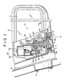
- Fig. 1 is a partially cutaway front view of an electrically foldable door mirror;
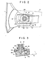
- Fig. 2 is a sectional plan view taken on line II-II of Fig. 1;
- Fig. 3 is a vertical sectional view taken on line III-III of Fig. 2;
- Fig. 4 is a cross-sectional plan view showing a portion of said door mirror folded backward;
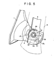
- Fig. 5 is a cross-sectional plan view showing a portion of said door mirror folded forward;
- Fig. 6 is an exploded view showing the relation between a shaft on a base and a mirror body;
- Fig. 7 is a perspective view showing a fixed clutch and a clutch gear;
- Figs. 8 and 9 are perspective views showing modified examples of Fig. 7;
- Fig. 10 is a plan view sh'owing the relation between a pinion and said clutch gear.
- The present invention will now be described with reference to the attached drawings. It is to be noted that the attached drawings show a righthand door mirror, drawings of a left-hand door mirror being omitted.
- In the embodiment, as shown in Figs. 1 and 2, electric driving means 10, such as a DC electric motor with reduction gears, is disposed within a
mirror body 5, apinion 18 being fastened to the output shaft of said electric driving means 10, saidpinion 18 being engaged with aclutch gear 20 attached to the upper portion of ashaft 6, anupper clutch 26a being disposed between the upper surface of saidclutch gear 20 and the upper end of saidshaft 6, alower clutch 26b being disposed between the lower surface of a frame at the position of insertion of saidshaft 6 and the opposing surface of a base, a coiledspring 24 being provided around saidshaft 6 so as to give a force of engagement to both of saidclutches upper clutch 26a being slightly more strongly engaged than saidlower clutch 26b. When the door mirror is electrically folded, the rotation of thepinion 18 disengages the weakly engagedlower clutch 26b so that themirror body 5 can be turned. In manual operation, when themirror body 5 is forcibly turned by hand, thelower clutch 26b is disengaged and then theupper clutch 26a is disengaged so that themirror body 5 can be turned, because thepinion 18 is engaged with theclutch gear 20. When themirror body 5 receives an external shock, both the upper andlower clutches mirror body 5 can be turned. In this way, theclutches mirror body 5. - Parts of the door mirror will now be described in detail. In Figs. 1 and 2, numeral 1 represents a base fastened, for example, to the triangular corner 2 of a door window of a motor vehicle by means of
screws 3.Numeral 4 represents a bracket extending approximately horizontally from the lower portion of the base 1. Numeral 5 represents a mirror body. Numeral 6 represents a shaft erected on thebracket 4.Numeral 14 represents a mirror, andnumeral 13 represents a pivot thereof. - Since the
mirror body 5 illustrated in Fig. 1 contains anactuator 30 for changing the angle of reflection of the mirror, theshaft 6 has a central hole through which a harness 7 passes. When themirror body 5 does not contain such an actuator, theshaft 6 is not required to be hollow. In Fig. 1, theshaft 6 is a member separate from the base 1, and is secured thereto at itsroot portion 36 by means of screws 9. However, theshaft 6 may be formed integrally with the base 1, and in this case securing by means of screws is eliminated. - A
frame 8 is secured within themirror body 5, and saidactuator 30 is disposed approximately in the center of theframe 8. Theframe 8 supports, near the base 1, electric driving means 10 which gives a driving force for the folding operation of the door mirror, and theframe 8 has a shaft bearing 12 into which theshaft 6 is inserted. The electric driving means 10 comprises a DCelectric motor 15 and agear box 16 containing reduction gears. Apinion 18 is secured to theoutput shaft 17 of thegear box 16. In Fig. 1, thepinion 18 is secured to theoutput shaft 17 by means of apin 19. Alternatively thepinion 18 may be secured thereto by press fit or by means of a key and a key way. - As shown in Fig. 6, the shaft bearing 12 of the
frame 8 is slightly tapered, and theshaft 6 has a taper portion 6a corresponding thereto. When the shaft bearing 12 of theframe 8 is put on the taper portion 6a of theshaft 6, thewhole frame 8 is rotatable and axially slidable with relation to theshaft 6. - The
shaft 6 has acylindrical portion 6b above said taper portion 6a, and aclutch gear 20 engaged with saidpinion 18 is attached to thecylindrical portion 6b. Theshaft 6 has anarrow portion 6c above saidcylindrical portion 6b, and afixed clutch 21 is fixed to thenarrow portion 6c. The opposing surfaces of theclutch gear 20 and the fixedclutch 21 form anupper clutch 26a. The upper clutch 26a may be, as shown in Fig. 7, a ball clutch comprising a plurality of (three in Fig. 7) holes 37 respectively provided in the upper surface of theclutch gear 20 and the lower surface of the fixed clutch 21, andballs 38 fitted in said holes 37. Alternatively the upper clutch 26a may comprise sidge-shaped catches 22 (Fig. 8) or tooth- shaped catches 23 (Fig. 9). - A
coiled spring 24 is disposed around the shaft bearing 12 so as to give a force of engagement to both of said upper clutch 26a and a lower clutch 26b described below. - As shown in Fig. 6, the lower clutch 26b is a ball
clutch comprising holes shaft 6 and a corresponding surface (b) of theframe 8, andballs 28 fitted in saidholes balls 28 of the lower clutch 26b more shallowly in the holes or making theballs 28 larger, as compared with theballs 38 of the upper clutch 26a. Thus, for example when themirror body 5 is turned by hand, the lower clutch 26b is disengaged slightly earlier than the upper clutch 26a so that themirror body 5 can be turned smoothly. - According to the present invention, it is possible to set the limits of turning of the
mirror body 5 in order to prevent damage to the outer panel of the vehicle. - For this purpose, the door mirror has stopping means and detecting means. The stopping means comprises, as shown in Fig. 6, a
stopper 31 disposed outside the surface (a) around the root portion of theshaft 6, andprojections segmental projection 32 formed on the surface (b) of theframe 8. Thereby, the stopping means mechanically sets the limits of turning of themirror body 5. - The
stopper 31 is disposed on the locus of turning of theprojections mirror body 5 is turned backward as shown in Fig. 4, the end (c) of theprojection 33 contacts the end (d) of thestopper 31 so that themirror body 5 cannot turn any more. When themirror body 5 is turned forward as shown in Fig. 5, the end (g) of theother projection 34 contacts the end (h) of thestopper 31 so that themirror body 5 cannot turn any more. - The detecting means comprises a limit switch LS, for detecting the normal position (neutral position) of the
mirror body 5, and another limit switch LS2 for detecting the position of the rear turning limit of themirror body 5. The limit switch LS, is buried, near the base 1, beside the surface (a) as shown in Fig. 6. When themirror body 5 is in the neutral position, the surface (f) of theprojection 34 pushes down the plunger (not shown) of the limit switch LS, so as to actuate the limit switch LS,. The limit switch LS2 is buried beside thestopper 31 as shown in Fig. 6. When themirror body 5 is turned backward to the limit as shown in Fig. 4, the surface (e) of theprojection 33 pushes down the plunger of the limit switch LS2 so as to actuate the limit switch LS2. These limit switches LSI, LS2 are contained in the driving circuit of the DCelectric motor 15. When any of the limit switches LS" LS2 is actuated after the main switch is turned on, the DCelectric motor 15 is stopped. - The operation of the door mirror will now be described.
- Figs. 1 and 2 show the state that the
mirror body 5 is erected, that is, themirror body 5 stays in the normal position. In this state, the upper clutch 26a and the lower clutch 26b are respectively engaged by the force of the coiledspring 24. Also, the surface (f) (Fig. 6) of theframe 8 is in contact with the limit switch LS, and the DCelectric motor 15 is stopped. - The upper clutch 26a is slightly more strongly engaged than the lower clutch 26b as mentioned above. Therefore, when the door mirror is electrically folded, only the lower clutch 26b is disengaged and the engagement of the upper clutch 26a is maintained, thus the
mirror body 5 being turned by thepinion 18 and theclutch gear 20. If the load becomes larger at this time, the upper clutch 26a is disengaged so that the mechanism driving thepinion 18 is not overloaded. When the door mirror is folded by hand, the lower clutch 26b is disengaged first, and then the upper clutch 26a is disengaged. When the door mirror receives an external shock, both upper clutch 26a and the lower clutch 26b are disengaged at the same time, and themirror body 5 is turned by the external force. When themirror body 5 is turned, it can be stopped at any angle within the limit of turning. - Torque required for disengaging the .upper clutch 26a and the lower clutch 26b will be described first. The rotation of the DC
electric motor 15 is slowed down by thegear box 16 and transmitted through thepinion 18 to theclutch gear 20 so as to cause relative rotation to the shaft - bearing 12 into which theshaft 6 is inserted. If torque required for disengaging the upper clutch 26a is represented by "Ta" and torque required for disengaging the lower clutch 26b is represented by "Tb", then
balls 28 of the lower clutch 26b from theholes 27 around the root portion of theshaft 6 onto the surface (a) while theballs 28 are held in theholes 29 in the surface (b) of the frame (8). Therefore, within the range of this torque, the upper clutch 26a between theclutch gear 20 and the fixed clutch 21 is not disengaged. Thus, theclutch gear 20 is not rotated and thepinion 18 rotates both round theclutch gear 20 and on its axis (Fig. 10) so as to turn themirror body 5. - If the DC
electric motor 15 is actuated when themirror body 5 is in the neutral position, theframe 8 turns on theshaft 6 with the rotation of thepinion 18 because theclutch gear 20 is unrotat- ably engaged with the fixedclutch 21. If the DCelectric motor 15 is stopped when themirror body 5 is at a desired angle (for example, about 45°), themirror body 5 is maintained in that position with theclutch gear 20 engaged with thepinion 18. - If it is necessary to turn the
mirror body 5 further to the rear turning limit, the DCelectric motor 15 is continued to be actuated to turn themirror body 5 further. Then, the turning of themirror body 5 is mechanically stopped when the end (c) of theprojection 33 contacts the end (d) of thestopper 31, and at the same time the DCelectric motor 15 is automatically deenergized because the surface (e) of theprojection 33 pushes down the plunger of the limit switch LS2 for detecting the position of the rear turning limit of the mirror body 5 (See Fig. 3). Now themirror body 5 is stopped at the position of the rear turning limit as shown in Fig. 4. - If the DC
electric motor 15 is reversed by means of the main switch when themirror body 5 is in an arbitrary rear position or the position of the rear turning limit, thepinion 18 is rotated in the direction opposite to the direction shown in Fig. 10. This rotation of thepinion 18 turns themirror body 5 until theballs 28 held in the holes 29 (Fig. 6) in the surface (b) of theframe 8 enter theholes 27 in the surface (a) around theshaft 6. At this time, the surface (f) of theprojection 34 on theframe 8 pushes down the plunger of the limit switch LS, and the DCelectric motor 15 is stopped thereby. In this way, themirror body 5 is returned to the position shown in Fig. 2. - The door mirror receives different external forces and operates differently according to whether it is folded by manual operation or by external shock.
- In manual operation, the
pinion 18 engaged with theclutch gear 20 is rotated slowly, and in the meanwhile the weakly engaged lower clutch 26b is disengaged. Then, a thrust in the axial direction of theclutch gear 20 is produced by a tangential force exerted on the balls 38 (Fig. 7) or catches 22, 23 (Figs. 8 and 9) of the upper clutch 26a. As a result, theclutch gear 20 is slightly pushed down along thecylindrical portion 6b and disengaged from the fixedclutch 21. Therefore, themirror body 5 can be manually turned on theshaft 6. - If the
mirror body 5 receives an external shock which is larger than said torque Ta for disengaging the upper clutch 26a when the motor vehicle is in operation or at a stop, both the upper clutch 26a and the lower clutch 26b are disengaged at the same time and themirror body 5 is turned forward or backward. - The
mirror body 5 in the neutral position can be turned forward to a desired position by hand. If themirror body 5 is turned forward further, the end (g) of theprojection 34 contacts the end (h) of thestopper 31 and therefore themirror body 5 is stopped at the position of the front turning limit as shown in Fig. 5. If there is a limit switch (not shown) for detecting the position of the front turning limit, themirror body 5 can be returned, by remote control, to the neutral position from the position of the front turning limit in the same way as from the position of the rear turning limit. - As is evident from the foregoing, the door mirror has means for automatically stopping the electric driving means, said stopping means being disposed between one surface of a fixed clutch fixed to the upper end of said shaft and a surface of a mirror body opposing said one surface of the fixed clutch, said stopping means comprising a printed circuit and contact pieces slidable thereon. Therefore, in the position of the turning limit, the switch for detecting the position of the turning limit is open, and the mirror body is automatically stopped and kept in this position. If the electric driving means is reversed by means of the operation switch, the mirror body is turned from the position of the turning limit to the neutral (erected) position and kept in the neutral position.
Claims (5)
Applications Claiming Priority (4)
| Application Number | Priority Date | Filing Date | Title |
|---|---|---|---|
| JP59131995A JPS6112452A (en) | 1984-06-28 | 1984-06-28 | Motor-driven inclining type door mirror |
| JP131995/84 | 1984-06-28 | ||
| JP60029472A JPS61191447A (en) | 1985-02-19 | 1985-02-19 | Electrically-operated retractable door mirror |
| JP29472/85 | 1985-02-19 |
Related Child Applications (1)
| Application Number | Title | Priority Date | Filing Date |
|---|---|---|---|
| EP87116946.2 Division-Into | 1987-11-17 |
Publications (2)
| Publication Number | Publication Date |
|---|---|
| EP0166378A1 EP0166378A1 (en) | 1986-01-02 |
| EP0166378B1 true EP0166378B1 (en) | 1989-01-11 |
Family
ID=26367679
Family Applications (2)
| Application Number | Title | Priority Date | Filing Date |
|---|---|---|---|
| EP19850107640 Expired EP0166378B1 (en) | 1984-06-28 | 1985-06-20 | Electrically foldable door mirror |
| EP19870116946 Expired EP0305590B1 (en) | 1984-06-28 | 1985-06-20 | Electrically foldable door mirror |
Family Applications After (1)
| Application Number | Title | Priority Date | Filing Date |
|---|---|---|---|
| EP19870116946 Expired EP0305590B1 (en) | 1984-06-28 | 1985-06-20 | Electrically foldable door mirror |
Country Status (2)
| Country | Link |
|---|---|
| EP (2) | EP0166378B1 (en) |
| DE (2) | DE3567417D1 (en) |
Families Citing this family (21)
| Publication number | Priority date | Publication date | Assignee | Title |
|---|---|---|---|---|
| JPS60148738A (en) * | 1984-01-12 | 1985-08-06 | Ichikoh Ind Ltd | Door mirror structure |
| US4692000A (en) * | 1984-11-12 | 1987-09-08 | Ichikoh Industries, Ltd. | Motor-driven collapsible door mirror |
| US4919526A (en) * | 1987-10-27 | 1990-04-24 | Ichikoh Industries Ltd. | Electrically swingable door mirror |
| DE3805354C1 (en) * | 1988-02-20 | 1989-08-24 | Daimler-Benz Aktiengesellschaft, 7000 Stuttgart, De | Wing mirror for vehicles |
| IT1227450B (en) * | 1988-11-02 | 1991-04-11 | Righi Nardino Cologno Monzese | CONTROL DEVICE FOR THE ROTATION OF AN EXTERNAL REAR-VIEW MIRROR. |
| GB8914707D0 (en) * | 1989-06-27 | 1989-08-16 | Britax Geco Sa | Exterior view mirror for a motor vehicle |
| US4981349A (en) * | 1989-09-01 | 1991-01-01 | Kabushiki Kaisha Matsuyama Seisakusho | Rearview mirror assembly for automobiles including positioning means with a recess surface extending uniformly horizontally |
| IT217190Z2 (en) * | 1989-09-22 | 1991-11-12 | Gilardini Spa | EXTERIOR REAR VIEW MIRROR FOR VEHICLE |
| DE3933641C2 (en) * | 1989-10-07 | 1998-11-26 | Bernhard Mittelhaeuser | Exterior rear view mirror for motor vehicles |
| JP2584198Y2 (en) * | 1991-03-27 | 1998-10-30 | 株式会社ホンダロック | Driving force connection / disconnection mechanism for vehicle mirror |
| JPH04136949U (en) * | 1991-06-17 | 1992-12-21 | 株式会社村上開明堂 | foldable door mirror |
| IT1252140B (en) * | 1991-11-29 | 1995-06-05 | Commer Spa | DEVICE FOR THE CONTROLLED ROTATION OF AN EXTERNAL REAR-VIEW MIRROR |
| JP2602999Y2 (en) * | 1991-12-26 | 2000-02-07 | 株式会社村上開明堂 | Electric retractable door mirror control device |
| IT1256710B (en) * | 1992-12-11 | 1995-12-15 | DEVICE TO CONTROL THE ROTATION OF AN EXTERNAL REAR-VIEW MIRROR UP TO A PREFIXED POSITION. | |
| ES2069490B1 (en) * | 1993-07-14 | 1998-06-01 | Fico Mirrors Sa | AUTOMATIC BLASTING MECHANISM FOR VEHICLE EXTERIOR MIRRORS. |
| DE4337750A1 (en) * | 1993-11-05 | 1995-05-11 | Bosch Gmbh Robert | Motor vehicle exterior mirror |
| DE19521432C2 (en) * | 1995-06-15 | 1999-07-01 | Hohe Gmbh & Co Kg | Vehicle exterior mirror with motorized pivoting mirror head |
| DE19644658B4 (en) * | 1996-10-25 | 2005-10-27 | Hohe Gmbh & Co. Kg | Exterior mirrors for a vehicle |
| DE29621153U1 (en) | 1996-12-05 | 1998-04-02 | Hohe GmbH & Co. KG, 97903 Collenberg | Wing mirror hinge |
| US6825282B2 (en) | 1999-06-04 | 2004-11-30 | Bayer Aktiengesellschaft | Diene rubber compounds for improved rubber moldings |
| JP6482353B2 (en) | 2015-03-31 | 2019-03-13 | 株式会社村上開明堂 | Electric retractable visual recognition device for vehicles |
Family Cites Families (3)
| Publication number | Priority date | Publication date | Assignee | Title |
|---|---|---|---|---|
| DE7503867U (en) * | 1975-02-08 | 1976-10-14 | Hohe Kg, 6981 Collenberg | Adjustable exterior rear-view mirror for motor vehicles |
| DE8209925U1 (en) * | 1982-04-07 | 1982-07-29 | MEKRA Rangau Plastics GmbH & Co KG, 8510 Fürth | Pivoting rearview mirror that can be adjusted by motor around a vertical axis |
| DE255150T1 (en) * | 1983-12-17 | 1988-06-09 | Ichikoh Industries Ltd., Tokio/Tokyo | EXTERNAL REAR VIEW MIRROR. |
-
1985
- 1985-06-20 DE DE8585107640T patent/DE3567417D1/en not_active Expired
- 1985-06-20 EP EP19850107640 patent/EP0166378B1/en not_active Expired
- 1985-06-20 DE DE8787116946T patent/DE3584978D1/en not_active Expired - Fee Related
- 1985-06-20 EP EP19870116946 patent/EP0305590B1/en not_active Expired
Also Published As
| Publication number | Publication date |
|---|---|
| EP0305590B1 (en) | 1991-12-18 |
| DE3584978D1 (en) | 1992-01-30 |
| EP0166378A1 (en) | 1986-01-02 |
| EP0305590A1 (en) | 1989-03-08 |
| DE3567417D1 (en) | 1989-02-16 |
Similar Documents
| Publication | Publication Date | Title |
|---|---|---|
| US4626084A (en) | Electrically foldable door mirror | |
| US4626083A (en) | Electrically foldable door mirror | |
| EP0305590B1 (en) | Electrically foldable door mirror | |
| US5384660A (en) | Foldable outside rearview mirror | |
| US5477390A (en) | Mirror assembly powered into rearwardly folded position against reversing spring bias | |
| US7172298B2 (en) | Power fold mechanism for vehicle mirrors | |
| EP0587994B1 (en) | Electrically powered foldable outer rearview mirror for motor vehicles | |
| EP1908635B1 (en) | Vehicle outside mirror device | |
| EP0801609B1 (en) | Exterior mirror with single pivot power fold | |
| EP0151642B1 (en) | Rearview mirror for vehicle | |
| US5828504A (en) | Exterior rearview mirror for a vehicle | |
| EP0182260B1 (en) | Motor-driven collapsible door mirror | |
| EP0616923A1 (en) | Electrically foldable outer rearview mirror for a motor vehicle | |
| WO2019026959A1 (en) | Electric retractable vehicle periphery viewing device | |
| US6929372B2 (en) | Power fold mechanism for double arm mirrors | |
| US20050105199A1 (en) | Mirror parking mechanism | |
| JPH01127430A (en) | Rear underview mirror for automobile | |
| KR20020010566A (en) | A mirror rotation mechanism | |
| JP7318221B2 (en) | Perimeter vision device for electric retractable vehicle | |
| EP0209296A2 (en) | Exterior rear-View Mirror | |
| KR0116317Y1 (en) | Sliding Structure of Rear View Mirror Stay | |
| KR940000043B1 (en) | Automotive Rearview Mirror with Power Rotator | |
| KR890004566Y1 (en) | Rear-view back mirror for vehicle | |
| KR950002752Y1 (en) | Automatic opening and closing device of car side mirror | |
| KR0122212Y1 (en) | Side mirror with assistance mirror for an automobile |
Legal Events
| Date | Code | Title | Description |
|---|---|---|---|
| PUAI | Public reference made under article 153(3) epc to a published international application that has entered the european phase |
Free format text: ORIGINAL CODE: 0009012 |
|
| AK | Designated contracting states |
Designated state(s): DE GB |
|
| 17P | Request for examination filed |
Effective date: 19860514 |
|
| 17Q | First examination report despatched |
Effective date: 19870515 |
|
| GRAA | (expected) grant |
Free format text: ORIGINAL CODE: 0009210 |
|
| AK | Designated contracting states |
Kind code of ref document: B1 Designated state(s): DE GB |
|
| REF | Corresponds to: |
Ref document number: 3567417 Country of ref document: DE Date of ref document: 19890216 |
|
| PLBE | No opposition filed within time limit |
Free format text: ORIGINAL CODE: 0009261 |
|
| STAA | Information on the status of an ep patent application or granted ep patent |
Free format text: STATUS: NO OPPOSITION FILED WITHIN TIME LIMIT |
|
| 26N | No opposition filed | ||
| PGFP | Annual fee paid to national office [announced via postgrant information from national office to epo] |
Ref country code: GB Payment date: 20000607 Year of fee payment: 16 |
|
| PGFP | Annual fee paid to national office [announced via postgrant information from national office to epo] |
Ref country code: DE Payment date: 20000629 Year of fee payment: 16 |
|
| PG25 | Lapsed in a contracting state [announced via postgrant information from national office to epo] |
Ref country code: GB Free format text: LAPSE BECAUSE OF NON-PAYMENT OF DUE FEES Effective date: 20010620 |
|
| GBPC | Gb: european patent ceased through non-payment of renewal fee |
Effective date: 20010620 |
|
| PG25 | Lapsed in a contracting state [announced via postgrant information from national office to epo] |
Ref country code: DE Free format text: LAPSE BECAUSE OF NON-PAYMENT OF DUE FEES Effective date: 20020403 |