EP0165940B1 - Filter with integral structural framework - Google Patents
Filter with integral structural framework Download PDFInfo
- Publication number
- EP0165940B1 EP0165940B1 EP84904318A EP84904318A EP0165940B1 EP 0165940 B1 EP0165940 B1 EP 0165940B1 EP 84904318 A EP84904318 A EP 84904318A EP 84904318 A EP84904318 A EP 84904318A EP 0165940 B1 EP0165940 B1 EP 0165940B1
- Authority
- EP
- European Patent Office
- Prior art keywords
- media
- filter
- area
- sheet
- filler material
- Prior art date
- Legal status (The legal status is an assumption and is not a legal conclusion. Google has not performed a legal analysis and makes no representation as to the accuracy of the status listed.)
- Expired - Lifetime
Links
Images


Classifications
-
- B—PERFORMING OPERATIONS; TRANSPORTING
- B01—PHYSICAL OR CHEMICAL PROCESSES OR APPARATUS IN GENERAL
- B01D—SEPARATION
- B01D46/00—Filters or filtering processes specially modified for separating dispersed particles from gases or vapours
- B01D46/10—Particle separators, e.g. dust precipitators, using filter plates, sheets or pads having plane surfaces
Definitions
- the present invention relates to a self-supporting microfiltration air filter for computer disc drive cabinets, and a process of manufacturing the filter.
- the filter of the invention is of the type having an air-impermeable structurally integral frame surrounding an active-filtering area of fibrous filter media and providing structural support for said active-filtering area, wherein the perimeter of said fibrous filter media, co-planar with said active-filtering area thereof, is solidified by the integral incorporation of impervious resin filler materials so that the fiber structure and thickness of said solidified media is substantially unaltered and undamaged by the filler material at the interface between the solidified perimeter and the active filtering area, at least one face of said solidified perimeter providing a substantially solid and impermeable surface which may be adhesively attached to a filter supporting substrate.
- a filter of this type wherein the frame is liquid- impermeable is disclosed in US-A-2147792.
- FIGS. 1 and 2 of the drawings Prior art breather-type microfilters, currently available commercially, have generally been of two types. These two types are illustrated in FIGS. 1 and 2 of the drawings and will be discussed in greater detail in the description which follows. While each prior art microfilter has served its purpose, a persistent problem remains with both filters, namely the potential for un-filtered air flow to leak past the filter as a result of ineffective bonding of the filter to the mounting surface, as well as, migration of contaminants at the juncture of the media and media holder interface along and below the surface of the media into the "clean air" side of the filter.
- the present invention is a significant advance in the art which will substantially eliminate the potential for leakage.
- the present invention is a filter of the type referred to above, having the characterizing features of claim 1.
- the process of manufacturing the filter of the present invention includes the following steps:
- the resulting filter may then be secured to a mounting surface, e.g. a disc-drive cover plate, with only one mechanical seal between the integral framework of the filter and the impermeable mounting surface being required.
- a mounting surface e.g. a disc-drive cover plate
- the present invention makes possible a significant reduction in the thickness of a microfilter, and the filter of the present invention is substantially uniform in thickness.
- the prior art microfilters are not as "thin" as the present invention as each known prior art filter requires a structural add-on or framework which is exterior to the filter media, whereas the framework of the present invention filter is an interior part of the filter media.
- FIG. 1 there is shown a solid mounting substrate 11 which typically has a plurality of openings 12 for allowing air flow to pass therethrough from an exterior side 13 of the mounting substrate 11 to an opposite interior side 14.
- a microfilter 15 is secured to the inside substrate surface 14, over the openings 12, to serve as a breather element for the device, e.g. computer disc-drive, and to prohibit any particulate matter from entering the disc-drive area otherwise protected from airflow.
- Both prior art filters shown in FIGS. 1 and 2 use conventional, laminated high- efficiency particulate air filter media (hereinafter referred to as HEPA media).
- HEPA media laminated high- efficiency particulate air filter media
- the laminated or layered filter media has a center layer 16 of glass-fibers covered on both sides by a layer of lightweight, permeable polyester scrim 17, 18.
- the layers 17, 18 of scrim allow the media to be handled and processed without undue damage to the glass-fibers of the center layer 16.
- the three layers 16, 17, 18 of the filter media are typically
- the filter media is sealed or bonded to a relatively rigid holder 20.
- the holder 20 may be plastic and generally has a circular shape and a central, indented portion 27 for receiving the media.
- the media is bonded to the indented portion 27 of the holder 20.
- the holder 20 and media form a two-component filter structure 15 which is then sealed to the substrate 11 by a thin adhesive ring 21 positioned between the holder 20 and substrate surface 14.
- arrows designated by the leters A AA show potential flow paths for unfiltered air to escape past the filter media in the event either or both of the filter's sealed areas proves ineffective.
- FIG. 2 A similar potential for leakage exists with the prior art microfilter shown in FIG. 2.
- the filter media is in direct contact with the surface 14 of the substrate 11 as no intevening media holder is used.
- a piece of adhesive tape 25 is applied to the HEPA media inward of the media perimiter and extended outward beyond the media a sufficient distance to secure the filter media when placed over the substrate openings 12.
- the portion 26 of the tape 25 which is not in contct with the media, instead is placed in contact with the surface 14 of the substrate 11 to secure the filter in position relative to the openings 12.
- two different areas must be sealed before the filter is functional, i.e.
- FIG. 2 arrows designated by the letters B, BB indicate the possible flow paths for unfiltered air flow which might occur as a result of an ineffective bonding of either or both sealed areas in the prior art filter.
- the media selected to illustrate this embodiment is scrimmed, layered HEPA media as described above. It will be readily appreciated, however, that the invention is applicable to other types of media, including non-scrimmed HEPA media, synthetic as well as natural fiber media, and media of various efficiency levels for applications other than breather-type filter applications.
- the objectives of the present invention include (1) a significant reduction in the potential for unfiltered air flow to leak past the filter media and (2) a significant reduction in filter thickness. These objectives are accomplished by the process for manufacturing the invention.
- a preferred mechanism for practicing the process for manufacturing the filter of the present invention is a combination of silk-screen printing and laser-cutting technology.
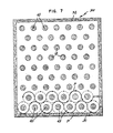
- FIG. 3 a portion of a silk-screen sheet 30 of multiple filters is illustrated as would apear before a laser is used to cut the sheet into individual filters 35 like that shown in FIG. 4.
- the following steps are taken with respect to the silk- screen/laser mechanism:
- a jig (not shown) could be constructed where the media is placed between a combination of stationary members which serve to mask selected areas of the media and contain the filler material therebetween, and movable arms arranged relative to the stationary members to force the filler material into the fiber structure of the media.
- stationary members which serve to mask selected areas of the media and contain the filler material therebetween
- movable arms arranged relative to the stationary members to force the filler material into the fiber structure of the media.
- An important feature of the present invention is that regardless of the particular mechanism selected to practice the manufacturing process, the process steps essential to the invention remain the same, i.e.: (a) the use of a sheet of filter media: (b) masking selected portions of the media sheet in order to provide an active filtering media area for the filter end- product; (c) placing a liquid-phase filler material in contact with the remaining exposed media areas; (d) applying sufficient pressure to the filler material in order to force the material into the media to the degree necessary to fully saturate the media and (e) after achieving complete saturation of the unmasked portions, removing the source of pressure and allowing the filler material to solidify.
- the individual filters may then be cut apart from each other.
- the end product is the filter of the present invention, namely, a filter having a self-supporting framework which is not only continuous with the active filtering media area, but is structurally integral with the media and which seals that portion of the media containing the filler material so as to be impermeable to air flow and contaminants.
- FIG. 8 a cross-sectional view of the present invention may be compared with the exploded cross-sectional views of the two prior art filters shown in FIGS. 1 and 2.
- the single-piece construction of the present invention is unique from the two-piece constructions of both prior art filters.
- the diffusion of the filler material through the fiber structure of the media accomplished without damage to the fibers and without material change in the thickness of the media, results in a filter which is substantially uniform in thickness having portions of media containing filler material which are impervious.
- the resulting filter thickness is substantially equivalent to the thickness of the media itself.
- the thickness of the prior art filter shown in FIG. 2 is a "double" nature as its two-part construction creates an additional area for leakage of unfiltered air which is not found in the present invention.
- a major difference between the present invention and the prior art filters is the elimination of one of two potential seal leakage areas. This is accomplished by eliminating the need to mechanically bond the filter media to any holder 20 or adhesive tape 25 in order to provide the media structural integrity.
- the filter of the present invention requires only one mechanical seal between its structurally integral framework 45 and the substrate mounting surface 14.
- FIG. 9 the magnified cross-sectional view shows portions of both the active filtering media area 40 and the air-impermeable framwork area 45 of the filter. It can be seen in FIG. 9 that the adhesive of the strip 50 will encapsulate any fibers extending from the framework 45 and fill any voids which might otherwise exist in the interface between the adhesive ring 50 and the surface of the framework 45 to which the strip is adhered.
- This interface area is illustrated by the contrasting crosshatched region of the adhesive ring 50.
- a significant reduction in leakage potential is achieved by the present invention over the prior art in that the greatest potential for leakage is eliminated when it is not necessary to interface the air permeable media with an adhesive or an exterior holder.
- the present invention may be mass-produced as described above. This results in a significant commercial advantage over the prior art filters which typically are produced individually in step-by-step mechanical processes. Further, the use of laser technology to separate or cut the mass-produced filters apart from each provides another major advantage. Also, the "free" or cut peripheral edges of the filter media are encapsulated in the flexible resin framework thus minimizing any shedding of glass-fibers from the cut edges as compared to prior art filters where is is possible for fibers to be freed in the mounting process and potentially cause damage.
- thermosetting and thermoplastic resin may be used as the filter material.
- resins including thermosetting and thermoplastic resin
- Such materials may include hot melt plastics, urethanes, plastisols, epoxies, phenolic and ultraviolet (U.V.) cured resins, waxes, rubber-latex resins, etc.
- Such materials may also be selected from two-part resins. The process for manufacture would be modified accordingly as dictated by the type of resin selected in order to obtain the required liquid-phase and curing aspects for the particular material. Because of the variety of possible filler materials, the integral framwork can be made pliable or rigid to varying degrees.
- the resin and hence the saturated media may be tinted in a variety of colors and textures to aid quality control measures, e.g., such as verifying alignment of the saturation pattern on both faces of the media with respect to each other, and aid in verifying full resin penetration.
- the filter may be finished, without or with surface tack adhesion as an inherent property of the filler-resin material or by a separate silk-screening step of applying an adhesive film or material to the surface of the resin framework portion of the filter sheet. These options may be used in lieu of applying a separate adhesive ring 50 to the filter as described above.
Abstract
Description
- The present invention relates to a self-supporting microfiltration air filter for computer disc drive cabinets, and a process of manufacturing the filter.
- More particularly the filter of the invention is of the type having an air-impermeable structurally integral frame surrounding an active-filtering area of fibrous filter media and providing structural support for said active-filtering area, wherein the perimeter of said fibrous filter media, co-planar with said active-filtering area thereof, is solidified by the integral incorporation of impervious resin filler materials so that the fiber structure and thickness of said solidified media is substantially unaltered and undamaged by the filler material at the interface between the solidified perimeter and the active filtering area, at least one face of said solidified perimeter providing a substantially solid and impermeable surface which may be adhesively attached to a filter supporting substrate.
- A filter of this type wherein the frame is liquid- impermeable is disclosed in US-A-2147792.
- The advances in computer technology have required technological advances in the filters used in connection with the various components of the computers. This has been most evident with the microfilters used in disc-drive applications where it is critical to the operation of the computer that virtually no contaminants be allowed to enter the disc-drive. Generally the function of breather-type microfilters is to filter air passing through the filter as pressure differentials on opposing sides of the filter are equalized. The importance of such microfilters exists in the critical need to prevent head crashing and resulting loss of information stored in the computer's memory.
- Prior art breather-type microfilters, currently available commercially, have generally been of two types. These two types are illustrated in FIGS. 1 and 2 of the drawings and will be discussed in greater detail in the description which follows. While each prior art microfilter has served its purpose, a persistent problem remains with both filters, namely the potential for un-filtered air flow to leak past the filter as a result of ineffective bonding of the filter to the mounting surface, as well as, migration of contaminants at the juncture of the media and media holder interface along and below the surface of the media into the "clean air" side of the filter. The present invention is a significant advance in the art which will substantially eliminate the potential for leakage.
- Also, with the demand for more compact computers, the size of each computer component, including the microfilters, becomes a concern. Initially, the prior art microfilters were not designed for minimum size. Now they must be. The present invention addresses this requirement and provides a solution not available with the prior art.
- The present invention is a filter of the type referred to above, having the characterizing features of claim 1.
- The process of manufacturing the filter of the present invention includes the following steps:
- (a) positioning a sheet of filter media upon a surface;
- (b) masking the active-filtering area of the sheet of filter media and leaving a surrounding area of the sheet exposed;
- (c) contacting the exposed media area with a liquid-phase resin filler material;
- (d) applying a soruce of pressure to the filler material to force the resin filler material to penetrate and completely saturate the exposed media areas without substantially altering the thickness of the exposed media;
- (e) removing the source of pressure;
- (f) unmasking the masked area of the filter media; and
- (g) curing the saturated exposed media area whereby the resin filler material solidifies within the fiber structure of the media and encapsulates the fibers, making the saturated media impervious to air flow and contaminants, the media area saturated with the resin filler material being structurally integral and continuous with the earlier masked active-filtering media area forming a filter which is self-supporting.
- The resulting filter may then be secured to a mounting surface, e.g. a disc-drive cover plate, with only one mechanical seal between the integral framework of the filter and the impermeable mounting surface being required. Thus, where the prior art filters required two separate mechanical seals, the present invention requires only one with its integral framework serving as a media "seal".
- Further, the present invention makes possible a significant reduction in the thickness of a microfilter, and the filter of the present invention is substantially uniform in thickness. In contrast, the prior art microfilters are not as "thin" as the present invention as each known prior art filter requires a structural add-on or framework which is exterior to the filter media, whereas the framework of the present invention filter is an interior part of the filter media.
- These and other aspects and advantages of the present invention will be discussed further hereinafter in the detailed description which follows.
-
- FIG. 1 is an exploded view in cross-section of one prior art microfilter.
- FIG. 2 is an exploded view in cross-section of a second prior art microfilter.
- FIG. 3 is a fragmentary view in perspective of a sheet of filters manufactured in accordance with process of the present invention.
- FIG. 4 is a view in perspective of a filter of the present invention.
- FIG. 5 is a view in perspective of one side of a filter manufactured in accordance with the present invention.
- FIG. 6 is a view in perspective of the side of the filter opposite to that shown in Fig. 5.
- FIG. 7 is a plan view of a sheet of filters of the present invention and a pattern selected for cutting the filters apart from each other.
- FIG. 8 is a view in cross-section of the present invention shown in FIGS. 5 and 6 as mounted to a substrate.
- FIG. 9 is a schematic pictorial representation of a magnified portion of the view shown in FIG. 8.
- In order to fully appreciate the advances made by the present invention to the state of the art, two examples of known prior art filters will first be examined before the present invention is described. Like reference numerals are used throughout the several views to indicate identical or like elements.
- In FIG. 1 there is shown a solid mounting substrate 11 which typically has a plurality of
openings 12 for allowing air flow to pass therethrough from anexterior side 13 of the mounting substrate 11 to an oppositeinterior side 14. Amicrofilter 15 is secured to theinside substrate surface 14, over theopenings 12, to serve as a breather element for the device, e.g. computer disc-drive, and to prohibit any particulate matter from entering the disc-drive area otherwise protected from airflow. Both prior art filters shown in FIGS. 1 and 2 use conventional, laminated high- efficiency particulate air filter media (hereinafter referred to as HEPA media). The laminated or layered filter media has acenter layer 16 of glass-fibers covered on both sides by a layer of lightweight,permeable polyester scrim layers center layer 16. The threelayers - In the prior art microfilter shown in FIG. 1, the filter media is sealed or bonded to a relatively
rigid holder 20. Theholder 20 may be plastic and generally has a circular shape and a central, indentedportion 27 for receiving the media. The media is bonded to the indentedportion 27 of theholder 20. Together theholder 20 and media form a two-component filter structure 15 which is then sealed to the substrate 11 by a thinadhesive ring 21 positioned between theholder 20 andsubstrate surface 14. Thus, two seals are necessitated before the filter is functional in its inteded application. In FIG. 1 arrows designated by the leters A, AA show potential flow paths for unfiltered air to escape past the filter media in the event either or both of the filter's sealed areas proves ineffective. - A similar potential for leakage exists with the prior art microfilter shown in FIG. 2. In this filter application the filter media is in direct contact with the
surface 14 of the substrate 11 as no intevening media holder is used. To secure this type of filter 15' to the substrate 11 a piece ofadhesive tape 25 is applied to the HEPA media inward of the media perimiter and extended outward beyond the media a sufficient distance to secure the filter media when placed over thesubstrate openings 12. As a result, theportion 26 of thetape 25 which is not in contct with the media, instead is placed in contact with thesurface 14 of the substrate 11 to secure the filter in position relative to theopenings 12. Again, as with the prior art filter shown in FIG. 1, two different areas must be sealed before the filter is functional, i.e. the interface area between the filter media and thetape 25, and the interface area between thesubstrate surface 14 and thetape 25. These two "sealed" areas, however, are sources of potential leakage of unfiltered air flow. In FIG. 2 arrows designated by the letters B, BB indicate the possible flow paths for unfiltered air flow which might occur as a result of an ineffective bonding of either or both sealed areas in the prior art filter. - Despite the fact that the foregoing two examples are among the best breather-type filters commercially available for microfiltration in connection with applications such as computer disc- drives, the increasing demand for thinner filters with greatly reduced potential for leakage of unfiltered air flow, is high. Given the expensive nature of the device requiring the protective nature of a microfilter, such a demand is not insignificant nor ignored. Hence the development of the present invention which answers these particular needs of the industry.
- With reference to FIGS, 3-9 a preferred embodiment for the present invention will be described. The media selected to illustrate this embodiment is scrimmed, layered HEPA media as described above. It will be readily appreciated, however, that the invention is applicable to other types of media, including non-scrimmed HEPA media, synthetic as well as natural fiber media, and media of various efficiency levels for applications other than breather-type filter applications.
- The objectives of the present invention include (1) a significant reduction in the potential for unfiltered air flow to leak past the filter media and (2) a significant reduction in filter thickness. These objectives are accomplished by the process for manufacturing the invention.
- A preferred mechanism for practicing the process for manufacturing the filter of the present invention is a combination of silk-screen printing and laser-cutting technology. In FIG. 3 a portion of a silk-
screen sheet 30 of multiple filters is illustrated as would apear before a laser is used to cut the sheet intoindividual filters 35 like that shown in FIG. 4. To achieve the filter end product the following steps are taken with respect to the silk- screen/laser mechanism: - (1) A sheet of scrimmed HEPA media is placed on a stationary, generally impermeable, mounting surface. The sheet is suitably secured, e.g. with tape, to prevent any shifting of the sheet during the process.
- (2) A fine mesh, woven screen is then placed on the sheet, in contact with one surface of the media. The screen is earlier prepared such that portions of the screen are made impervious to fluid and air. The impervious portions overlie those portions of the media sheet which are selected to be active filtering media for the end filter procuct. The impervious portions of the screen mask the underlying portions of the media during the process.
- (3) After the screen is positioned in place on top of the media, a filler material, preferably a latex resin, either an emulsion or suspension in liquid-phase, is applied on top of the screen.
- (4) Mechanical force is then applied to the resin by using a conventional squeegee device. As the squeegee is passed over the screen, the blade of the squeegee forces resin downwardly through the openings in the screen and into the media therebelow.
- (5) The amount of resin forced into the media is metered by the selected number of passes which are made over the screen with the squeegee device. With each pass an additional amount of resin is applied to the screen.
- (6) The amount of resin forced into the media is equivalent to that determined necessary to completely saturate the media to at least to more than half the thickness of the media, and preferably through the entire thickness of the media.
- (7) In the preferred embodiment each side or face surface of the sheet of media is subjected to the forced penetration of liquid-phase resin in order to insure full-penetration of the resin throughout the portions of the media which are not masked.
- (8) When one side or surface of the media has been adequately penetrated and saturated with resin, the screen is removed and the saturated sheet of media is allowed to dry. The process is then repeated for the reverse side of the sheet. The selection of a symmetrical arrangement of masked portions allows alignment of respective masked portions on both side of the media sheet. Thus, the cured sheet of media shown in FIG. 3 would appear identical on its reverse side.
- (9) After step (8), the resin is allowed to cure and, together with the encapsulated media fibers, the cured resin forms a
structural framework 45 for the filter product. - (10) The amount of resin applied to the second side of the media sheet is that amont necessary to fully penetrate and saturate the depth of media untouched by application of resin to the first side of the media. A process of trial and error is used to determine the number of passes necessary to achieve one hundred percent saturation of the unmasked portions of the media. To verify that full penetration has been achieved the media is inspected to determine if delamination of the media layers is possible. If delamination is not possible then full penetration and complete saturation has been accomplished. Air impermeability off the resin-saturated portion of the resulting sheet of multiple filters may be further verified using an industry standard air permeability tester.
- (11) Depending on the type of resin selected, the curing steps of the process may require exposing the media to a source of heat for a period of time to insure the resin is cured to a degree where it will not redisperse.
- (12) When the resin in the media is cured such that it is immobilized and solidified the sheet is then ready to be cut into a number of separate filters.
- (13) In the present invention a computer-controlled laser-beam is used to cut and fuse the cut edges of each filter from the media sheet. The laser technology used in the preferred embodiment is state-of-the art technology available commercially, e.g. in the preferred embodiment laser technology available from Laserdyne, Inc. a division of Data Card Corporation, was selected.
- (14) With reference to FIG. 7, the cured sheet of media is placed on a stationary table. The computer of the laser machine is pre-programmed to move the laser beam through a selected pattern. In the preferred embodiment, the masked portions of the media are circular in shape and have been spaced apart from each other in rows which are offset with respect to adjacent rows on either side thereof. With this arrangement circular shaped filters are then cut. The pattern for this embodiment is essentially a serpentine line following a sine-wave pattern as reprsented by arrows P in FIG. 7. The laser beam is passed in this pattern from one
edge 31 to the opposingedge 32 of the sheet moving from row to row until the entire sheet has been cut. The end result is a number of mass-produced indentical circular filters of type illustrated in Fig. 4. - (15) The final step in the process is the application of a pliable
adhesive ring 50 to one side of the filter. The adhesive selected must be compatible with the resin used in the filter product to insure adequate adherence for the life of the filter. Thering 50 is adhesive on both sides. A silicone- treatedrelease paper 51 is placed over one side of the ring for shipping and handling purposes. When mounting the filter in its intended application therelease paper 51 is removed from theadhesive ring 50, exposing the adhesive for contact with a substrate surface, e.g. a cover plate for a computer disc-drive. - Of course, persons skilled in the art will appreciate that other mechanisms may be used to practice the present invention. For example, a jig (not shown) could be constructed where the media is placed between a combination of stationary members which serve to mask selected areas of the media and contain the filler material therebetween, and movable arms arranged relative to the stationary members to force the filler material into the fiber structure of the media. A number of variations for this type of mechanism are possible and the invention is thus not believed limited to any particular arrangement. An important feature of the present invention is that regardless of the particular mechanism selected to practice the manufacturing process, the process steps essential to the invention remain the same, i.e.: (a) the use of a sheet of filter media: (b) masking selected portions of the media sheet in order to provide an active filtering media area for the filter end- product; (c) placing a liquid-phase filler material in contact with the remaining exposed media areas; (d) applying sufficient pressure to the filler material in order to force the material into the media to the degree necessary to fully saturate the media and (e) after achieving complete saturation of the unmasked portions, removing the source of pressure and allowing the filler material to solidify. The individual filters may then be cut apart from each other. The end product is the filter of the present invention, namely, a filter having a self-supporting framework which is not only continuous with the active filtering media area, but is structurally integral with the media and which seals that portion of the media containing the filler material so as to be impermeable to air flow and contaminants.
- From an examination of FIGS. 8 and 9, the superior and novel features of the present invention over the prior art can be appreciated. In FIG. 8 a cross-sectional view of the present invention may be compared with the exploded cross-sectional views of the two prior art filters shown in FIGS. 1 and 2. The single-piece construction of the present invention is unique from the two-piece constructions of both prior art filters. The diffusion of the filler material through the fiber structure of the media, accomplished without damage to the fibers and without material change in the thickness of the media, results in a filter which is substantially uniform in thickness having portions of media containing filler material which are impervious. The resulting filter thickness is substantially equivalent to the thickness of the media itself. In contrast the thickness of the prior art filter in FIG. 1 includes not only the thickness of the media but that of the
holder 20 as well. Similarly, the thickness of the prior art filter shown in FIG. 2 is a "double" nature as its two-part construction creates an additional area for leakage of unfiltered air which is not found in the present invention. - A major difference between the present invention and the prior art filters is the elimination of one of two potential seal leakage areas. This is accomplished by eliminating the need to mechanically bond the filter media to any
holder 20 oradhesive tape 25 in order to provide the media structural integrity. The filter of the present invention requires only one mechanical seal between its structurallyintegral framework 45 and thesubstrate mounting surface 14. In FIG. 9 the magnified cross-sectional view shows portions of both the activefiltering media area 40 and the air-impermeable framwork area 45 of the filter. It can be seen in FIG. 9 that the adhesive of thestrip 50 will encapsulate any fibers extending from theframework 45 and fill any voids which might otherwise exist in the interface between theadhesive ring 50 and the surface of theframework 45 to which the strip is adhered. This interface area is illustrated by the contrasting crosshatched region of theadhesive ring 50. For unfiltered air to leak past the filter there must be an ineffective seal between thefilter framework 45 and the substrate 11 as the resin-filledmedia framework 45 itself is completely impermeable to air. Thus, a significant reduction in leakage potential is achieved by the present invention over the prior art in that the greatest potential for leakage is eliminated when it is not necessary to interface the air permeable media with an adhesive or an exterior holder. - Other advantages of the present invention over the prior art include the ability of the invention to survive the handling necessary to properly position the filter over the substrate openings. The unique construction of the present invention eliminates the possibility of the media delaminating when the filter is flexed while positioning it over the
substrate openings 12. This is because the flexible resin/fiber framework 45 is integral with the media itself. This is not true of the prior art filters where even minimal handling, such as that necessary to merely position the filter accurately over the substrate openings, may cause delamination of the filter's component layers and shedding of potentially damaging particles. With the present invention's framwork 45 a flexibility and durability is provided which allows tremendously more handling to be possible when mounting the filter than could ever be hoped for with the prior art filters. - Furthermore the present invention may be mass-produced as described above. This results in a significant commercial advantage over the prior art filters which typically are produced individually in step-by-step mechanical processes. Further, the use of laser technology to separate or cut the mass-produced filters apart from each provides another major advantage. Also, the "free" or cut peripheral edges of the filter media are encapsulated in the flexible resin framework thus minimizing any shedding of glass-fibers from the cut edges as compared to prior art filters where is is possible for fibers to be freed in the mounting process and potentially cause damage.
- From the foregoing it will be appreciated that a variety of resins, including thermosetting and thermoplastic resin may be used as the filter material. Such may include hot melt plastics, urethanes, plastisols, epoxies, phenolic and ultraviolet (U.V.) cured resins, waxes, rubber-latex resins, etc. Such materials may also be selected from two-part resins. The process for manufacture would be modified accordingly as dictated by the type of resin selected in order to obtain the required liquid-phase and curing aspects for the particular material. Because of the variety of possible filler materials, the integral framwork can be made pliable or rigid to varying degrees. Also the resin and hence the saturated media may be tinted in a variety of colors and textures to aid quality control measures, e.g., such as verifying alignment of the saturation pattern on both faces of the media with respect to each other, and aid in verifying full resin penetration. Furthermore, the filter may be finished, without or with surface tack adhesion as an inherent property of the filler-resin material or by a separate silk-screening step of applying an adhesive film or material to the surface of the resin framework portion of the filter sheet. These options may be used in lieu of applying a separate
adhesive ring 50 to the filter as described above.
Claims (6)
Priority Applications (1)
| Application Number | Priority Date | Filing Date | Title |
|---|---|---|---|
| AT84904318T ATE59790T1 (en) | 1983-11-23 | 1984-11-21 | FILTER WITH INTEGRAL STRUCTURE. |
Applications Claiming Priority (2)
| Application Number | Priority Date | Filing Date | Title |
|---|---|---|---|
| US55482883A | 1983-11-23 | 1983-11-23 | |
| US554828 | 1983-11-23 |
Publications (3)
| Publication Number | Publication Date |
|---|---|
| EP0165940A1 EP0165940A1 (en) | 1986-01-02 |
| EP0165940A4 EP0165940A4 (en) | 1986-03-18 |
| EP0165940B1 true EP0165940B1 (en) | 1991-01-09 |
Family
ID=24214863
Family Applications (1)
| Application Number | Title | Priority Date | Filing Date |
|---|---|---|---|
| EP84904318A Expired - Lifetime EP0165940B1 (en) | 1983-11-23 | 1984-11-21 | Filter with integral structural framework |
Country Status (5)
| Country | Link |
|---|---|
| EP (1) | EP0165940B1 (en) |
| JP (4) | JPS61500598A (en) |
| AU (1) | AU564569B2 (en) |
| DE (1) | DE3483910D1 (en) |
| WO (1) | WO1985002351A1 (en) |
Cited By (1)
| Publication number | Priority date | Publication date | Assignee | Title |
|---|---|---|---|---|
| DE29601847U1 (en) * | 1996-02-03 | 1997-03-13 | Weil Peter | Filter mat for removing dust, especially fine dust |
Families Citing this family (12)
| Publication number | Priority date | Publication date | Assignee | Title |
|---|---|---|---|---|
| GB2266672B (en) * | 1992-05-09 | 1995-05-03 | Scapa Group Plc | Improvements in or relating to filter cloths |
| EP0871533A1 (en) | 1995-05-12 | 1998-10-21 | Donaldson Company, Inc. | Filter device |
| EP0844903A1 (en) * | 1995-06-20 | 1998-06-03 | Donaldson Company, Inc. | Filter and method for making a filter |
| DE69634687T2 (en) | 1995-07-27 | 2006-03-16 | Taisei Corp. | AIR FILTER |
| US6929985B2 (en) | 1995-07-27 | 2005-08-16 | Taisei Corporation | Air filter, method of manufacturing air filter, local facility, clean room, treating agent, and method of manufacturing filter medium |
| GB9724814D0 (en) * | 1997-11-25 | 1998-01-21 | Rhodes Harry G | Filtration assembly |
| US6662955B1 (en) * | 1998-08-11 | 2003-12-16 | Food Equipment Technologies Company Inc. | Beverage ingredient filter and assembly |
| US6419729B1 (en) * | 2000-04-17 | 2002-07-16 | 3M Innovative Properties Company | Filter assemblies with adhesive attachment systems |
| JP4474391B2 (en) * | 2006-08-10 | 2010-06-02 | トヨタ自動車株式会社 | Gas filtration device |
| IL185431A0 (en) * | 2007-08-22 | 2008-01-06 | Shay Brosh | Method and external, disposable filter for home computers |
| US8794238B2 (en) * | 2010-12-28 | 2014-08-05 | 3M Innovative Properties Company | Splash-fluid resistant filtering face-piece respirator |
| JP2019512379A (en) | 2016-02-26 | 2019-05-16 | スリーエム イノベイティブ プロパティズ カンパニー | Air conditioner filter and manufacturing method |
Citations (2)
| Publication number | Priority date | Publication date | Assignee | Title |
|---|---|---|---|---|
| US2147792A (en) * | 1937-04-09 | 1939-02-21 | Zella F Campbell | Filter |
| US2591490A (en) * | 1946-03-01 | 1952-04-01 | Electrolux Corp | Air filter |
Family Cites Families (8)
| Publication number | Priority date | Publication date | Assignee | Title |
|---|---|---|---|---|
| US2521984A (en) * | 1947-05-19 | 1950-09-12 | American Felt Co | Fibrous unit |
| US3408438A (en) * | 1964-02-05 | 1968-10-29 | G S Staunton & Co Inc | Method of making self-supporting filter element |
| JPS425677Y1 (en) * | 1964-07-10 | 1967-03-20 | ||
| JPS5380070A (en) * | 1976-12-24 | 1978-07-15 | Hitachi Ltd | Air filter and manufacture of same |
| GB1603519A (en) * | 1978-01-23 | 1981-11-25 | Process Scient Innovations | Filter elements for gas or liquid and methods of making such filters |
| DE2807546C2 (en) * | 1978-02-20 | 1984-02-16 | Auergesellschaft Gmbh, 1000 Berlin | Circular disk-shaped filter element made of sheet-like filter material folded in parallel and a process for its production |
| JPS6034337Y2 (en) * | 1980-08-20 | 1985-10-14 | 日本無機株式会社 | glass fiber filter media |
| US4340402A (en) * | 1980-10-14 | 1982-07-20 | Walt R. Philipanko | Disposable air filter |
-
1984
- 1984-11-21 AU AU36745/84A patent/AU564569B2/en not_active Ceased
- 1984-11-21 EP EP84904318A patent/EP0165940B1/en not_active Expired - Lifetime
- 1984-11-21 DE DE8484904318T patent/DE3483910D1/en not_active Expired - Fee Related
- 1984-11-21 WO PCT/US1984/001930 patent/WO1985002351A1/en active IP Right Grant
- 1984-11-21 JP JP50429684A patent/JPS61500598A/en active Pending
-
1989
- 1989-01-19 JP JP1093989A patent/JPH01288311A/en active Pending
-
1991
- 1991-03-18 JP JP1991068562U patent/JP2542262Y2/en not_active Expired - Lifetime
-
1995
- 1995-07-24 JP JP1995008920U patent/JP2548003Y2/en not_active Expired - Lifetime
Patent Citations (2)
| Publication number | Priority date | Publication date | Assignee | Title |
|---|---|---|---|---|
| US2147792A (en) * | 1937-04-09 | 1939-02-21 | Zella F Campbell | Filter |
| US2591490A (en) * | 1946-03-01 | 1952-04-01 | Electrolux Corp | Air filter |
Cited By (1)
| Publication number | Priority date | Publication date | Assignee | Title |
|---|---|---|---|---|
| DE29601847U1 (en) * | 1996-02-03 | 1997-03-13 | Weil Peter | Filter mat for removing dust, especially fine dust |
Also Published As
| Publication number | Publication date |
|---|---|
| AU564569B2 (en) | 1987-08-13 |
| JPH057316U (en) | 1993-02-02 |
| JP2548003Y2 (en) | 1997-09-17 |
| JPH01288311A (en) | 1989-11-20 |
| JPS61500598A (en) | 1986-04-03 |
| EP0165940A4 (en) | 1986-03-18 |
| WO1985002351A1 (en) | 1985-06-06 |
| AU3674584A (en) | 1985-06-13 |
| JPH08998U (en) | 1996-06-21 |
| JP2542262Y2 (en) | 1997-07-23 |
| EP0165940A1 (en) | 1986-01-02 |
| DE3483910D1 (en) | 1991-02-14 |
Similar Documents
| Publication | Publication Date | Title |
|---|---|---|
| US4600420A (en) | Filter with integral structural framework | |
| EP0165940B1 (en) | Filter with integral structural framework | |
| CA1193976A (en) | Membrane pack | |
| EP0567547B1 (en) | A smoke filter | |
| US5725937A (en) | Component of printed circuit boards | |
| US4465725A (en) | Noise suppression panel | |
| US5137622A (en) | Filter screen assembly | |
| US5185048A (en) | Method of manufacturing a separator frame for a stack in an exchanger device | |
| CA1211360A (en) | Means for attenuating sound energy, and method of manufacture thereof | |
| EP1003600B1 (en) | Plastic filtration unit and method for producing the same | |
| EP0339355B1 (en) | Drainage disc for membrane assembly | |
| AT346630B (en) | MULTI-LAYER WELDED EDGE RECORDING CARRIER AND METHOD OF MANUFACTURING A COMPOSITE INLET FOR THIS RECORDERING CARRIER | |
| US5433764A (en) | Disposable filter assembly | |
| AU610641B2 (en) | Process for producing a filter element | |
| DE1933737C3 (en) | Process for producing a magnetic recording medium | |
| JP2653121B2 (en) | Manufacturing method of filter package | |
| JPS6316019A (en) | Air filter paper | |
| JP3362549B2 (en) | Filter unit | |
| DE69333183T2 (en) | METHOD FOR PRODUCING A FILTRATION FILM ELEMENT | |
| US4960268A (en) | Spacer holder arrangement | |
| DE19502555C2 (en) | label | |
| JP3238480B2 (en) | Manufacturing method of membrane filter cassette | |
| JPS58149370A (en) | Connection of fiber | |
| JPH072048U (en) | Breathable material | |
| DE19820049A1 (en) | Thermomechanical process for the planarization of a layer that can be structured using photo technology, in particular encapsulation for electronic components |
Legal Events
| Date | Code | Title | Description |
|---|---|---|---|
| PUAI | Public reference made under article 153(3) epc to a published international application that has entered the european phase |
Free format text: ORIGINAL CODE: 0009012 |
|
| AK | Designated contracting states |
Designated state(s): AT BE CH DE FR GB LI LU NL SE |
|
| 17P | Request for examination filed |
Effective date: 19851204 |
|
| A4 | Supplementary search report drawn up and despatched |
Effective date: 19860318 |
|
| 17Q | First examination report despatched |
Effective date: 19871204 |
|
| GRAA | (expected) grant |
Free format text: ORIGINAL CODE: 0009210 |
|
| AK | Designated contracting states |
Kind code of ref document: B1 Designated state(s): AT BE CH DE FR GB LI LU NL SE |
|
| PG25 | Lapsed in a contracting state [announced via postgrant information from national office to epo] |
Ref country code: SE Effective date: 19910109 Ref country code: NL Effective date: 19910109 Ref country code: AT Effective date: 19910109 |
|
| REF | Corresponds to: |
Ref document number: 59790 Country of ref document: AT Date of ref document: 19910115 Kind code of ref document: T |
|
| REF | Corresponds to: |
Ref document number: 3483910 Country of ref document: DE Date of ref document: 19910214 |
|
| ET | Fr: translation filed | ||
| NLV1 | Nl: lapsed or annulled due to failure to fulfill the requirements of art. 29p and 29m of the patents act | ||
| PLBE | No opposition filed within time limit |
Free format text: ORIGINAL CODE: 0009261 |
|
| STAA | Information on the status of an ep patent application or granted ep patent |
Free format text: STATUS: NO OPPOSITION FILED WITHIN TIME LIMIT |
|
| PG25 | Lapsed in a contracting state [announced via postgrant information from national office to epo] |
Ref country code: LU Free format text: LAPSE BECAUSE OF NON-PAYMENT OF DUE FEES Effective date: 19911130 |
|
| 26N | No opposition filed | ||
| PGFP | Annual fee paid to national office [announced via postgrant information from national office to epo] |
Ref country code: GB Payment date: 20000512 Year of fee payment: 16 |
|
| PGFP | Annual fee paid to national office [announced via postgrant information from national office to epo] |
Ref country code: CH Payment date: 20000515 Year of fee payment: 16 |
|
| PGFP | Annual fee paid to national office [announced via postgrant information from national office to epo] |
Ref country code: FR Payment date: 20000519 Year of fee payment: 16 |
|
| PGFP | Annual fee paid to national office [announced via postgrant information from national office to epo] |
Ref country code: DE Payment date: 20000531 Year of fee payment: 16 |
|
| PGFP | Annual fee paid to national office [announced via postgrant information from national office to epo] |
Ref country code: BE Payment date: 20000620 Year of fee payment: 16 |
|
| PG25 | Lapsed in a contracting state [announced via postgrant information from national office to epo] |
Ref country code: GB Free format text: LAPSE BECAUSE OF NON-PAYMENT OF DUE FEES Effective date: 20001121 |
|
| PG25 | Lapsed in a contracting state [announced via postgrant information from national office to epo] |
Ref country code: LI Free format text: LAPSE BECAUSE OF NON-PAYMENT OF DUE FEES Effective date: 20001130 Ref country code: CH Free format text: LAPSE BECAUSE OF NON-PAYMENT OF DUE FEES Effective date: 20001130 Ref country code: BE Free format text: LAPSE BECAUSE OF NON-PAYMENT OF DUE FEES Effective date: 20001130 |
|
| BERE | Be: lapsed |
Owner name: DONALDSON CY INC. Effective date: 20001130 |
|
| GBPC | Gb: european patent ceased through non-payment of renewal fee |
Effective date: 20001121 |
|
| REG | Reference to a national code |
Ref country code: CH Ref legal event code: PL |
|
| PG25 | Lapsed in a contracting state [announced via postgrant information from national office to epo] |
Ref country code: FR Free format text: LAPSE BECAUSE OF NON-PAYMENT OF DUE FEES Effective date: 20010731 |
|
| PG25 | Lapsed in a contracting state [announced via postgrant information from national office to epo] |
Ref country code: DE Free format text: LAPSE BECAUSE OF NON-PAYMENT OF DUE FEES Effective date: 20010801 |
|
| REG | Reference to a national code |
Ref country code: FR Ref legal event code: ST |