EP0165609B1 - Temperature moderation of an oxygen enriched claus sulfur plant - Google Patents
Temperature moderation of an oxygen enriched claus sulfur plant Download PDFInfo
- Publication number
- EP0165609B1 EP0165609B1 EP85107637A EP85107637A EP0165609B1 EP 0165609 B1 EP0165609 B1 EP 0165609B1 EP 85107637 A EP85107637 A EP 85107637A EP 85107637 A EP85107637 A EP 85107637A EP 0165609 B1 EP0165609 B1 EP 0165609B1
- Authority
- EP
- European Patent Office
- Prior art keywords
- sulfur
- stream
- effluent
- oxygen
- reaction furnace
- Prior art date
- Legal status (The legal status is an assumption and is not a legal conclusion. Google has not performed a legal analysis and makes no representation as to the accuracy of the status listed.)
- Expired
Links
Images
Classifications
-
- C—CHEMISTRY; METALLURGY
- C01—INORGANIC CHEMISTRY
- C01B—NON-METALLIC ELEMENTS; COMPOUNDS THEREOF; METALLOIDS OR COMPOUNDS THEREOF NOT COVERED BY SUBCLASS C01C
- C01B17/00—Sulfur; Compounds thereof
- C01B17/02—Preparation of sulfur; Purification
- C01B17/04—Preparation of sulfur; Purification from gaseous sulfur compounds including gaseous sulfides
- C01B17/0404—Preparation of sulfur; Purification from gaseous sulfur compounds including gaseous sulfides by processes comprising a dry catalytic conversion of hydrogen sulfide-containing gases, e.g. the Claus process
- C01B17/0413—Preparation of sulfur; Purification from gaseous sulfur compounds including gaseous sulfides by processes comprising a dry catalytic conversion of hydrogen sulfide-containing gases, e.g. the Claus process characterised by the combustion step
-
- Y—GENERAL TAGGING OF NEW TECHNOLOGICAL DEVELOPMENTS; GENERAL TAGGING OF CROSS-SECTIONAL TECHNOLOGIES SPANNING OVER SEVERAL SECTIONS OF THE IPC; TECHNICAL SUBJECTS COVERED BY FORMER USPC CROSS-REFERENCE ART COLLECTIONS [XRACs] AND DIGESTS
- Y10—TECHNICAL SUBJECTS COVERED BY FORMER USPC
- Y10S—TECHNICAL SUBJECTS COVERED BY FORMER USPC CROSS-REFERENCE ART COLLECTIONS [XRACs] AND DIGESTS
- Y10S423/00—Chemistry of inorganic compounds
- Y10S423/06—Temperature control
Definitions
- the present invention is directed to the recovery of elemental sulfur from hydrogen sulfide containing gas streams. More specifically, the present invention is directed to improvements in a Claus sulfur plant using oxygen enrichment and recycle gases to increase capacity and moderate flame temperatures in the reaction furnace.
- temperatures and sulfur condenser capacity may limit the potential capacity increase using oxygen enrichment.
- stream temperature in the reaction furnace and in the converter beds may increase due to oxygen enrichment and in fact such increase from oxygen enrichment reaches the maximum tolerable temperature of the materials used in such a furnace, namely the refractory lining.
- U.S. Patent 3,822,341 described a Claus plant using oxygen enrichment in which one source of oxygen is initially used to strip residual S0 2 from a sidestream in vessel 92 before the oxygen stream in line 96 is optionally recycled to be included with the oxygen in line 12 going to the combustion zone of the waste heat boiler 8. As recited at col. 5, lines 65-68 of the specification. Because the oxygen content of such a stream is completely consumed in an exothermic reaction this stream can be utilized as a moderating medium for the flame temperature of the reaction furnace. As described by Goar, Claus sulfur plants typically have an adiabatic reaction furnace followed by a waste heat boiler. The excessive temperature problem with oxygen enriched operation occurs in the adiabatic reaction furnace. U.S. 3,822,341 ignores the existence of this problem.
- U.S. Patent 4,153,674 dislcoses a Claus plant and tailgas cleanup plant wherein a gas stream in line 20 is removed from the tail gas system and is returned or recycled to the front end of the Claus plant 7.
- This patent does not consider oxygen enrichment or flame temperature moderation by a recycle stream. Also the tail gas is reacted to convert all sulfur to hydrogen sulfide which is absorbed, stripped and returned to the Claus plant.
- the present invention overcomes the shortcomings of the prior art by increasing through of a Claus plant by oxygen enrichment to an extent beyond that contemplated in the prior art due to flame temperature limitations. This is achieved by the recycle of an intermediate gas stream from the first condenser in the Claus train to moderate the temperature in the flame of the burner of the reaction furnace.
- the present invention is directed to a process for recovering sulfur from a feed gas stream rich in hydrogen sulfide wherein the gas stream is partially combusted with an oxygen-enriched gas in a Claus reaction furnace, the combustion effluent is cooled with the attendant condensation and separation of sulfur in the first condensation zone and the remaining effluent stream is passed through at least one stage of reheating, conversion in a catalytic Claus reaction zone and cooling with attendant condensation and separation of sulfur in an additional condensation zone, wherein the improvement comprises recycling a portion of the effluent stream from the first condensation zone to the reaction furnace zone to moderate the temperature of the reaction furnace zone.
- the process uses three stages of reheating, conversion and cooling and separation subsequent to the first condensation zone.
- the process is relevant for hydrogen sulfide containing streams wherein the sulfide is in the range of 60 to 100 mole %.
- the hydrogen sulfide content of the feed gas is 80 to 100 mole %.
- the oxygen enrichment of the reaction furnace is in the range of 32 to 90 mole %, more specifically 40-75 mole %.
- the recycle stream flow rate should be in the range of 5 to 60% of the combustion effluent stream from the first condensation zone.
- the temperature of the reaction furnace zone is maintained in the range of 1316-1538°C (2400 to 2800°F).
- the invention also is directed to a system for recovering sulfur from a feed gas stream rich in hydrogen sulfide by the Claus reaction including a reaction furnace for partially combusting the feed gas stream with an oxygen enriched gas, a first condensing means for cooling and condensing sulfur from the combustion effluent, at least one train comprising a reheater means, a catalytic Claus reactor and an additional condensing means, means for rewarming, further reacting and recovering sulfur from said effluent, wherein the improvement comprises recycle means for recycling a portion of the effluent from said first condensing means to said reaction furnace.
- the system has a recycle means constituting a conduit just downstream of the first condenser for recycling a portion of the combustion effluent gas through the conduit and delivered by a recycle blower through a subsequent conduit to the reaction furnace of the Claus plant system.
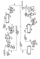
- the drawing is a schematic representation of the oxygen-enrichment and effluent recycle embodiment of a Claus plant.
- Claus sulfur recovery systems are widely utilized to recover sulfur from acid gas streams produced in natural gas purification and in petroleum refineries primarily from amine sweetening.
- hydrogen sulfide is in the crude oil and is contained in hydrocarbon desulfurization unit off gases and fluidized catalytic cracker unit off gases.
- acid gas stream produced from the amine unit is quite rich in hydrogen sulfide, particularly in petroleum refineries may be 80-95 mole % hydrogen sulfide.
- the Claus plant units are either fully loaded or subject to becoming fully loaded (capacity limited) due to the processing of heavy crude oils which contain relatively large amounts of sulfur compounds.
- One method which may be used to increase the capacity of an existing Claus plant is the use of oxygen to enrich the air stream to the reaction furnace of the plant from 21 mole % oxygen which is the content of air, up to 70-90 mole % oxygen or higher. Any increase in oxygen content of the air stream effectively reduces the nitrogen content of gases passing through the Claus plant and increases its throughput capacity for sulfur by diminishing the gas volume of inerts, namely nitrogen which must also be passed through the equipment.
- a Claus plant handling 80-95 mole % hydrogen sulfide acid gas needs an increase in capacity of 40-60%, yet only enough oxygen can be added to the air stream to get a 10-15% increase in capacity because flame temperature limitations of the fire brick and refractory in the reaction furnace limit the amount of oxygen which may be added. This results because of the increase in flame temperature when oxygen is added to the air stream.
- the calculated theoretical adiabatic flame temperature should be about 1316°C (2400°F). If the air stream is enriched with oxygen to 40 mole % oxygen, the calculated adiabatic theoretical flame temperature should increase to about 1732°C (3150°F). Again, if the air stream is enriched with oxygen, but this time to 70 mole % oxygen, the calculated theoretical adiabatic flame temperature should increase to about 2065°C (3750°F).
- the present invention permits increasing the oxygen enrichment to above 32 mole % to increase capacity of an existing Claus sulfur recovery unit further by recycling combustion effluent, after cooling to separate sulfur liquid, to moderate the reaction furnace temperature to avoid excessively high temperature.
- the recycle rate would be set to provide dilution and cooling to control the reaction furnace temperature in the 1316-1538°C (2400-2800°F) range.
- hydrogen sulfide feed and sulfur recovery capacity can be increased by 50-100% by enriching the air stream to 70 mole % oxygen when handling 90 mole % hydrogen sulfide acid gas feed.
- An acid gas feed stream is introduced into the Claus system in line 10 having a hydrogen sulfide content of 92 mole %.
- the feed is at a temperature of 37.8°C (100°F) and a pressure of 1.7 bar (25 psia).
- a recycle stream in line 18 is introduced into the acid gas feed stream 10 wherein the recycle stream comprises predominantly steam with lesser amounts of nitrogen, hydrogen sulfide, sulfur dioxide, carbon dioxide and hydrogen.
- the recycle is at approximately 177°C (350°F).
- the mixed gas stream is introduced into burner 20 along with air provided in line 14 at elevated pressure from compressor 16, as well as an oxygen stream 12 provided from any convenient source of commercially pure oxygen.
- the reactants are combusted in burner 20 and evolved into the reaction furnace 22 where the reactions of the Claus process occur. Specifically, in the burner hydrogen sulfide and oxygen combine to produce sulfur dioxide and water wherein one third of the reaction feed is initially combusted and the remaining two thirds react with the sulfur dioxide produced to produce sulfur and water according to the following formulaes:
- the reactor furnace effluent then passes through a circuitous heat exchange zone or waste heat boiler 24 wherein the combustion effluents are cooled against boiler feed water in line 26 which then produces steam in line 28.
- the reaction effluents are converted from one form of sulfur species to another according to the following equations:
- the cooled effluent from the waste heat boiler in line 30 is at a temperature of 316°C (600°F) and a pressure of 1.66 bar (24 psia). It is then introduced into the first condenser 32 wherein the effluent is again heat exchanged to cool the effluent against boiler feed water in line 34 which produces steam in line 36. Liquid sulfur is condensed out in line 38 constituting 77.4% of the sulfur in the feed, and the gaseous combustion effluent stream is removed in line 40.
- stream 40 Approximately 45% of the effluent stream 40 is then split into line 44 as an intermediate recycle stream taken immediately downstream from the condenser 32 and recycled through blower 46 to be fed in line 18 into the acid gas feed line 10 in order to moderate the temperature of the flame in the burner 20.
- This stream again is at a temperature of 177°C (350°F).
- stream 18 can be introduced into burner 20, line 12 or line 14.
- the remaining stream in line 42 is then reheated in a reheater heat exchanger 48 against process stream.
- the stream now in line 50 has been reheated to a temperature of 221°C (430°F) and is then introduced into a catalytic converter reactor 52 wherein additional quantities of hydrogen sulfide and sulfur dioxide are reacted to produce sulfur and water according to the following equations:
- reaction stream now in line 54 is introduced into a second condenser 56 which again cools the effluent stream against boiler feed water in line 58 to produce additional steam in line 60.
- Additional elemental sulfur is recovered in line 62 constituting 14.3% of the sulfur into the feed to the process, wherein the sulfur species produced in the catalytic reaction are converted to high molecular weight sulfur species and then are condensed to elemental sulfur according the following reactions:
- the stream in line 64 is at a temperature of 171°C (340°F) and a pressure of bar (22 psia). It is introduced into reheater heat exchanger 66 and heated against process steam to produce a stream in line 68 at 216°C (420°F). This stream is introduced into a second catalyst converter 70 wherein a similar catalytic reaction between hydrogen sulfide and sulfur dioxide occurs with the catalytic effluent in line 72 going to yet another condenser 74 which is cooled with boiler feed water 76 to produce steam in line 78. An additional quantity of liquid elemental sulfur is removed in line 80 constituting 4.9% of the sulfur in the feed to the process.
- the effluent stream in line 82 is at 166°C (330°F) and 1.38 bar (20 psia) before it is further reheated in reheater heat exchanger 84 against process steam to produce a stream in line 86 at 204°C (400°F) and 1.38 bar (20 psia).
- This stream is introduced into the third and final catalytic reactor 88 to react substantially the remaining hydrogen sulfide and sulfur dioxide to produce sulfur species which are removed in line 90 wherein that stream is introduced into a condenser 92 cooled by boiler feed water in line 94 producing steam in line 96.
- the stream in line 100 is introduced into a tailgas coalescer 102 wherein additional sulfur is removed in line 104.
- the residual stream in lines 106 and 107 is then introduced into a tail gas cleaning unit (TGCU) where the bulk of the residual sulfur constituents of 106 are recovered to meet sulfur emission environmental standards typically by conversion to hydrogen sulfide which is returned to the acid gas feed 10.
- TGCU tail gas cleaning unit
- the tail gas is sent to an incinerator burner 112 that is fired with natural gas in line 108 and air in line 110.
- the materials are then vented in stack 114, at an acceptable sulfur content level, as an effluent 116 to the atmosphere.
- the present invention as described above is exemplary of only one embodiment of the invention which incorporates oxygen enrichment with an intermediate recycle stream to provide: a) an unexpected degree of freedom in oxygen enrichment, b) an increase in throughput of a Claus plant to very high levels, c) a decrease in overall pressure drop through the Claus plant system, d) reduced effluent flow to and through the tailgas process unit, and e) heightened percent recovery of sulfur from the feed gas stream, wherein the intermediate recycle provides a unique moderate of flame temperatures in an oxygen enriched Claus plant.
Landscapes
- Chemical & Material Sciences (AREA)
- Organic Chemistry (AREA)
- Inorganic Chemistry (AREA)
- Engineering & Computer Science (AREA)
- Combustion & Propulsion (AREA)
- Chemical Kinetics & Catalysis (AREA)
- Treating Waste Gases (AREA)
- Separation Using Semi-Permeable Membranes (AREA)
- Solid-Sorbent Or Filter-Aiding Compositions (AREA)
- Organic Low-Molecular-Weight Compounds And Preparation Thereof (AREA)
- Physical Or Chemical Processes And Apparatus (AREA)
Description
- The present invention is directed to the recovery of elemental sulfur from hydrogen sulfide containing gas streams. More specifically, the present invention is directed to improvements in a Claus sulfur plant using oxygen enrichment and recycle gases to increase capacity and moderate flame temperatures in the reaction furnace.
- It is known in the prior art to recover elemental sulfur from hydrogen sulfide containing gas streams as is set forth in the article "Fundamentals of Sulfur Recovery by the Claus Process" by B. Gene Goar, published in the 1977 Gas Conditioning Conference Report.
- It is also known to use oxygen enrichment in the operation of a Claus sulfur plant in order to increase the capacity of hydrogen sulfide handled as well as the total throughput of the plant as set forth in the article "Oxygen Use in Claus Sulfur Plants" by M. R. Gray and W. Y. Svrcek published in the 1981 Gas Conditioning Conference Report. In that article it was disclosed that oxygen can be added to the air feed to the burner of the reaction furnace in order to increase the amount of hydrogen sulfide which is combusted to sulfur dioxide for later catalyst conversion with additional hydrogen sulfide to the elemental liquid sulfur product of the Claus process. The article recites that the maximum capacity increase which can be achieved with oxygen enrichment is determined by the pressure drop through the plant and the reactor space velocities. However, a further limitation set forth in the article is that for a given plant stream, temperatures and sulfur condenser capacity may limit the potential capacity increase using oxygen enrichment. Specifically, stream temperature in the reaction furnace and in the converter beds may increase due to oxygen enrichment and in fact such increase from oxygen enrichment reaches the maximum tolerable temperature of the materials used in such a furnace, namely the refractory lining.
- In the 1983 publication by Linde of Union Carbide entitled "Claus Plant Oxygen Enrichment", it is noted that oxygen-enrichment limitations exist for rich H2S streams due to temperature limits in the furnace or waste heat boiler of a Claus plant.
- U.S. Patent 3,822,341 described a Claus plant using oxygen enrichment in which one source of oxygen is initially used to strip residual S02 from a sidestream in
vessel 92 before the oxygen stream inline 96 is optionally recycled to be included with the oxygen in line 12 going to the combustion zone of the waste heat boiler 8. As recited at col. 5, lines 65-68 of the specification. Because the oxygen content of such a stream is completely consumed in an exothermic reaction this stream can be utilized as a moderating medium for the flame temperature of the reaction furnace. As described by Goar, Claus sulfur plants typically have an adiabatic reaction furnace followed by a waste heat boiler. The excessive temperature problem with oxygen enriched operation occurs in the adiabatic reaction furnace. U.S. 3,822,341 ignores the existence of this problem. - U.S. Patent 4,153,674 dislcoses a Claus plant and tailgas cleanup plant wherein a gas stream in
line 20 is removed from the tail gas system and is returned or recycled to the front end of the Claus plant 7. This patent does not consider oxygen enrichment or flame temperature moderation by a recycle stream. Also the tail gas is reacted to convert all sulfur to hydrogen sulfide which is absorbed, stripped and returned to the Claus plant. - The present invention overcomes the shortcomings of the prior art by increasing through of a Claus plant by oxygen enrichment to an extent beyond that contemplated in the prior art due to flame temperature limitations. This is achieved by the recycle of an intermediate gas stream from the first condenser in the Claus train to moderate the temperature in the flame of the burner of the reaction furnace.
- The present invention is directed to a process for recovering sulfur from a feed gas stream rich in hydrogen sulfide wherein the gas stream is partially combusted with an oxygen-enriched gas in a Claus reaction furnace, the combustion effluent is cooled with the attendant condensation and separation of sulfur in the first condensation zone and the remaining effluent stream is passed through at least one stage of reheating, conversion in a catalytic Claus reaction zone and cooling with attendant condensation and separation of sulfur in an additional condensation zone, wherein the improvement comprises recycling a portion of the effluent stream from the first condensation zone to the reaction furnace zone to moderate the temperature of the reaction furnace zone.
- Typically the process uses three stages of reheating, conversion and cooling and separation subsequent to the first condensation zone.
- The process is relevant for hydrogen sulfide containing streams wherein the sulfide is in the range of 60 to 100 mole %. Preferably the hydrogen sulfide content of the feed gas is 80 to 100 mole %.
- Preferably the oxygen enrichment of the reaction furnace is in the range of 32 to 90 mole %, more specifically 40-75 mole %.
- The recycle stream flow rate should be in the range of 5 to 60% of the combustion effluent stream from the first condensation zone.
- Preferably the temperature of the reaction furnace zone is maintained in the range of 1316-1538°C (2400 to 2800°F).
- The invention also is directed to a system for recovering sulfur from a feed gas stream rich in hydrogen sulfide by the Claus reaction including a reaction furnace for partially combusting the feed gas stream with an oxygen enriched gas, a first condensing means for cooling and condensing sulfur from the combustion effluent, at least one train comprising a reheater means, a catalytic Claus reactor and an additional condensing means, means for rewarming, further reacting and recovering sulfur from said effluent, wherein the improvement comprises recycle means for recycling a portion of the effluent from said first condensing means to said reaction furnace.
- Preferably the system has a recycle means constituting a conduit just downstream of the first condenser for recycling a portion of the combustion effluent gas through the conduit and delivered by a recycle blower through a subsequent conduit to the reaction furnace of the Claus plant system.
- The drawing is a schematic representation of the oxygen-enrichment and effluent recycle embodiment of a Claus plant.
- Claus sulfur recovery systems are widely utilized to recover sulfur from acid gas streams produced in natural gas purification and in petroleum refineries primarily from amine sweetening. In refineries the hydrogen sulfide is in the crude oil and is contained in hydrocarbon desulfurization unit off gases and fluidized catalytic cracker unit off gases. Often times the acid gas stream produced from the amine unit is quite rich in hydrogen sulfide, particularly in petroleum refineries may be 80-95 mole % hydrogen sulfide. Also in many refineries, the Claus plant units are either fully loaded or subject to becoming fully loaded (capacity limited) due to the processing of heavy crude oils which contain relatively large amounts of sulfur compounds. With the dwindling known reserves of refinable hydrocarbons and crude oils, less attractive known oil reserves are now being processed which Iss attractice oil reserves typically have high sulfur contents. The trend in refining such high sulfur containing feedstocks will increase in the future. Therefore a method for increasing the capacity of Claus plants to process sulfur is needed.
- As Claus sulfur recovery unit feed rates are increased above capacity several problems develop. At increased flow the pressure drop through the Claus plant and tail gas cleanup unit increases and the back pressure increases required H2S and air feed inlet pressures beyond what is available from the amine regenerator that supplied the H2S feed and the air blower that provides feed air. The increased flow also increases the space velocity in the reaction furnace and the catalytic reactor stages which reduces conversion to sulfur and increases emissions to the tail gas cleanup unit. The increased flows to th tail gas cleanup unit increases its pressure drop and further lowers tail gas sulfur recover to give increased and usually unacceptable sulfur emissions. The increased back pressures may in some Claus plants pose the risk of blowing the liquid sulfur drain seals which would release noxious, toxic H2S into the area. Whle booster blowers for the H2S and air feeds, and higher pressure sulfur liquid drain seals can provide some increase in capacity the reduced sulfur conversion and increased sulfur emissions remain.
- One method which may be used to increase the capacity of an existing Claus plant is the use of oxygen to enrich the air stream to the reaction furnace of the plant from 21 mole % oxygen which is the content of air, up to 70-90 mole % oxygen or higher. Any increase in oxygen content of the air stream effectively reduces the nitrogen content of gases passing through the Claus plant and increases its throughput capacity for sulfur by diminishing the gas volume of inerts, namely nitrogen which must also be passed through the equipment. Typically, a Claus plant handling 80-95 mole % hydrogen sulfide acid gas needs an increase in capacity of 40-60%, yet only enough oxygen can be added to the air stream to get a 10-15% increase in capacity because flame temperature limitations of the fire brick and refractory in the reaction furnace limit the amount of oxygen which may be added. This results because of the increase in flame temperature when oxygen is added to the air stream.
- If the acid gas stream contains 90 mole % hydrogen sulfude and the Claus plant is performing a typical burn of only one third of the hydrogen sulfide (one third of fully stoichiometric air requirements) and the burner is receiving air (21 mole % oxygen) then the calculated theoretical adiabatic flame temperature should be about 1316°C (2400°F). If the air stream is enriched with oxygen to 40 mole % oxygen, the calculated adiabatic theoretical flame temperature should increase to about 1732°C (3150°F). Again, if the air stream is enriched with oxygen, but this time to 70 mole % oxygen, the calculated theoretical adiabatic flame temperature should increase to about 2065°C (3750°F). However, most better quality fire brick and refractory material installed in Claus plant reaction furnaces are good for a maximum continuous operating temperature of only 1482 to 1538°C (2700 to 2800°F) if they have an alumina content of 85-90 wt% or greater. Therfore, it may be seen from the above calculations that only a limited oxygen enrichment, 30-32 mole % oxygen of the airstream can be used and still hold the temperature below a maximum of 1538°C (2800°F). With the small reduction of nitrogen input when increasing the air stream oxygen content from 21-32 mole % oxygen, only a slight increase in Claus plant capacity is realized, approximately 12 to 15% capacity.
- The present invention however, permits increasing the oxygen enrichment to above 32 mole % to increase capacity of an existing Claus sulfur recovery unit further by recycling combustion effluent, after cooling to separate sulfur liquid, to moderate the reaction furnace temperature to avoid excessively high temperature. In practice the recycle rate would be set to provide dilution and cooling to control the reaction furnace temperature in the 1316-1538°C (2400-2800°F) range. With this technique hydrogen sulfide feed and sulfur recovery capacity can be increased by 50-100% by enriching the air stream to 70 mole % oxygen when handling 90 mole % hydrogen sulfide acid gas feed.
- By recycling a portion of the reacted and cooled reaction furnace stage sulfur condenser effluent gas to the input of the reaction furnace, particularly at the acid gas feed line to the burner, the flame temperatures associated with very high oxygen enrichments necessary to effect significant throughput increases are moderated by the relatively cool and reacted recycle gas emanating from the condenser. Alternately, the recycle could be added directly to the burner or to the air feed. The combination of oxygen enrichment and this intermediate recycle provides an unexpected potential enhancement of capacity or throughput for a Claus plant. Such a process configuration could be provided as a retrofit to a capacity limited existing Claus plant system or it could be provided in a smaller size new installation taking into account the increased capacity freedom provided by the oxygen enrichment and intermediate recycle atrributes.
- At first glance it may appear that the increased flow from the recycle stream will increase the Claus plant system pressure drop and reintroduce the pressure drop limitation which oxygen enrichment alleviated. This is not correct as can be seen from the Table which compares a bottlenecked air operation prior art system with the system debottlenecked using oxygen enrichment and intermediate recycle. The Table shows that going from the
Case 1 bottlenecked air operation to the Case 2 debottlenecked oxygen with intermediate recycle operation, the reaction furnace pressure differential is increased from 0.13-0.19 bar (1.9 to 2.8 psi) for the debottlenecked Case 2. However, the catalytic stages and the tailgas unit pressure drops are reduced from 0.62 to 0.23 bar (9.1 to 3.4 psi) for Case 2 because of the decrease in nitrogen flow through the stages. At the same time, overall sulfur recovery in the Claus unit has increased from 97;7 to 98.3% for the debottlenecked Case 2. The tailgas unit recovery would also increase at the lower flow rates and longer contact times. - While this discussion has shown that oxygen enrichment and the recycle technique of this invention can be used to increase the capacity of an existing plant, the same technique can be used in the design of new Claus sulfur recovery units to decrease the size of equipment required for a given capacity below what whould be required for air operation. In particular, the reduction of air input with consequent decrease in nitrogen input decreases the size and cost of the TGCU.

- The present invention will now be described in greater detail with reference to a preferred embodiment which is illustrated in the figure. An acid gas feed stream is introduced into the Claus system in line 10 having a hydrogen sulfide content of 92 mole %. The feed is at a temperature of 37.8°C (100°F) and a pressure of 1.7 bar (25 psia). A recycle stream in
line 18 is introduced into the acid gas feed stream 10 wherein the recycle stream comprises predominantly steam with lesser amounts of nitrogen, hydrogen sulfide, sulfur dioxide, carbon dioxide and hydrogen. The recycle is at approximately 177°C (350°F). The mixed gas stream is introduced intoburner 20 along with air provided in line 14 at elevated pressure from compressor 16, as well as an oxygen stream 12 provided from any convenient source of commercially pure oxygen. The reactants are combusted inburner 20 and evolved into thereaction furnace 22 where the reactions of the Claus process occur. Specifically, in the burner hydrogen sulfide and oxygen combine to produce sulfur dioxide and water wherein one third of the reaction feed is initially combusted and the remaining two thirds react with the sulfur dioxide produced to produce sulfur and water according to the following formulaes:

- Some hydrogen is also produced by hydrogen sulfide dissociation.


- The cooled effluent from the waste heat boiler in
line 30 is at a temperature of 316°C (600°F) and a pressure of 1.66 bar (24 psia). It is then introduced into thefirst condenser 32 wherein the effluent is again heat exchanged to cool the effluent against boiler feed water inline 34 which produces steam in line 36. Liquid sulfur is condensed out in line 38 constituting 77.4% of the sulfur in the feed, and the gaseous combustion effluent stream is removed in line 40. Approximately 45% of the effluent stream 40 is then split intoline 44 as an intermediate recycle stream taken immediately downstream from thecondenser 32 and recycled throughblower 46 to be fed inline 18 into the acid gas feed line 10 in order to moderate the temperature of the flame in theburner 20. This stream again is at a temperature of 177°C (350°F). Alternatively,stream 18 can be introduced intoburner 20, line 12 or line 14. - The remaining stream in
line 42 is then reheated in a reheater heat exchanger 48 against process stream. The stream now inline 50 has been reheated to a temperature of 221°C (430°F) and is then introduced into a catalytic converter reactor 52 wherein additional quantities of hydrogen sulfide and sulfur dioxide are reacted to produce sulfur and water according to the following equations:

- The reaction stream now in
line 54 is introduced into asecond condenser 56 which again cools the effluent stream against boiler feed water inline 58 to produce additional steam inline 60. Additional elemental sulfur is recovered in line 62 constituting 14.3% of the sulfur into the feed to the process, wherein the sulfur species produced in the catalytic reaction are converted to high molecular weight sulfur species and then are condensed to elemental sulfur according the following reactions:

- The stream in
line 64 is at a temperature of 171°C (340°F) and a pressure of bar (22 psia). It is introduced intoreheater heat exchanger 66 and heated against process steam to produce a stream inline 68 at 216°C (420°F). This stream is introduced into asecond catalyst converter 70 wherein a similar catalytic reaction between hydrogen sulfide and sulfur dioxide occurs with the catalytic effluent inline 72 going to yet anothercondenser 74 which is cooled with boiler feed water 76 to produce steam inline 78. An additional quantity of liquid elemental sulfur is removed inline 80 constituting 4.9% of the sulfur in the feed to the process. - The effluent stream in
line 82 is at 166°C (330°F) and 1.38 bar (20 psia) before it is further reheated inreheater heat exchanger 84 against process steam to produce a stream inline 86 at 204°C (400°F) and 1.38 bar (20 psia). This stream is introduced into the third and finalcatalytic reactor 88 to react substantially the remaining hydrogen sulfide and sulfur dioxide to produce sulfur species which are removed inline 90 wherein that stream is introduced into acondenser 92 cooled by boiler feed water inline 94 producing steam inline 96. Further elemental sulfur in liquid form is removed inline 98 constituting 1.7% of the sulfur in the feed to the process, while a final effluent is recovered inline 100 comprising predominantly steam, nitrogen, carbon dioxide, hydrogen and residual hydrogen sulfide and sulfur compounds amounting to 1.4 mole % of the effluent stream. - The stream in
line 100 is introduced into a tailgas coalescer 102 wherein additional sulfur is removed inline 104. The residual stream inlines incinerator burner 112 that is fired with natural gas inline 108 and air inline 110. The materials are then vented instack 114, at an acceptable sulfur content level, as aneffluent 116 to the atmosphere. - The present invention as described above is exemplary of only one embodiment of the invention which incorporates oxygen enrichment with an intermediate recycle stream to provide: a) an unexpected degree of freedom in oxygen enrichment, b) an increase in throughput of a Claus plant to very high levels, c) a decrease in overall pressure drop through the Claus plant system, d) reduced effluent flow to and through the tailgas process unit, and e) heightened percent recovery of sulfur from the feed gas stream, wherein the intermediate recycle provides a unique moderate of flame temperatures in an oxygen enriched Claus plant.
- The present invention has been described with regard to one preferred embodiment, but those skilled in the art will be capable of contemplating other variants which are deemed to be within the scope of the invention, which scope should be ascertained from the claims which follow.
Claims (12)
Applications Claiming Priority (2)
| Application Number | Priority Date | Filing Date | Title |
|---|---|---|---|
| US622433 | 1984-06-20 | ||
| US06/622,433 US4552747A (en) | 1984-06-20 | 1984-06-20 | Temperature moderation of an oxygen enriched Claus sulfur plant |
Publications (3)
| Publication Number | Publication Date |
|---|---|
| EP0165609A2 EP0165609A2 (en) | 1985-12-27 |
| EP0165609A3 EP0165609A3 (en) | 1986-12-30 |
| EP0165609B1 true EP0165609B1 (en) | 1989-09-06 |
Family
ID=24494155
Family Applications (1)
| Application Number | Title | Priority Date | Filing Date |
|---|---|---|---|
| EP85107637A Expired EP0165609B1 (en) | 1984-06-20 | 1985-06-20 | Temperature moderation of an oxygen enriched claus sulfur plant |
Country Status (11)
| Country | Link |
|---|---|
| US (1) | US4552747A (en) |
| EP (1) | EP0165609B1 (en) |
| JP (1) | JP2615007B2 (en) |
| KR (1) | KR890001119B1 (en) |
| BR (1) | BR8503011A (en) |
| CA (1) | CA1212817A (en) |
| DE (1) | DE3572793D1 (en) |
| ES (2) | ES8802120A1 (en) |
| MX (1) | MX163365A (en) |
| NO (1) | NO167018C (en) |
| ZA (1) | ZA854627B (en) |
Cited By (10)
| Publication number | Priority date | Publication date | Assignee | Title |
|---|---|---|---|---|
| US9370745B2 (en) | 2013-04-24 | 2016-06-21 | Jiangsu New Century Jiangnan Environmental Protection Co., Ltd | Flue gas-treating method and apparatus for treating acidic tail gas by using ammonia process |
| US10092877B1 (en) | 2017-05-25 | 2018-10-09 | Jiangnan Environmental Protection Group Inc. | Dust removal and desulfurization of FCC exhaust gas |
| US10099170B1 (en) | 2017-06-14 | 2018-10-16 | Jiangnan Environmental Protection Group Inc. | Ammonia-adding system for ammonia-based desulfurization device |
| US10112145B1 (en) | 2017-09-07 | 2018-10-30 | Jiangnan Environmental Protection Group Inc. | Method for controlling aerosol production during absorption in ammonia desulfurization |
| US20190001267A1 (en) | 2017-07-03 | 2019-01-03 | Jiangnan Environmental Protection Group Inc. | Desulfurization absorption tower |
| US10207220B2 (en) | 2017-03-15 | 2019-02-19 | Jiangnan Environmental Protection Group Inc. | Method and apparatus for removing sulfur oxides from gas |
| US10561982B2 (en) | 2017-05-25 | 2020-02-18 | Jiangnan Environmental Protection Group Inc. | Ammonia-based desulfurization process and apparatus |
| US10953365B2 (en) | 2018-07-20 | 2021-03-23 | Jiangnan Environmental Protection Group Inc. | Acid gas treatment |
| US11027234B2 (en) | 2018-04-13 | 2021-06-08 | Jiangnan Environmental Protection Group Inc. | Oxidization of ammonia desulfurization solution |
| US11224838B2 (en) | 2019-12-26 | 2022-01-18 | Jiangnan Environmental Protection Group Inc. | Controlling aerosol production during absorption in ammonia-based desulfurization |
Families Citing this family (39)
| Publication number | Priority date | Publication date | Assignee | Title |
|---|---|---|---|---|
| US4632818A (en) * | 1984-10-03 | 1986-12-30 | Air Products And Chemicals, Inc. | Production of sulfur from an oxygen enriched claus system |
| US4826670A (en) * | 1985-03-20 | 1989-05-02 | Air Products And Chemicals, Inc. | Oxygen enriched claus system with sulfuric acid injection |
| GB8509393D0 (en) * | 1985-04-12 | 1985-05-15 | Boc Group Plc | Treatment of gases |
| US4844881A (en) * | 1986-02-24 | 1989-07-04 | The Boc Group, Inc. | Process for the production of sulfur from hydrogen sulfide using high concentration oxygen and recycle in combination with a scrubbing tower |
| EP0237216B1 (en) * | 1986-03-07 | 1991-05-22 | The BOC Group plc | Treatment of gas streams |
| DE3777861D1 (en) * | 1986-03-07 | 1992-05-07 | Boc Group Plc | TREATMENT OF GASES. |
| US4756900A (en) * | 1987-01-14 | 1988-07-12 | Amoco Corporation | Recycling of waste heat boiler effluent to an oxygen-enriched Claus reaction furnace |
| GB8710828D0 (en) * | 1987-05-07 | 1987-06-10 | Boc Group Inc | Treatment of gas streams |
| US5139765A (en) * | 1988-01-21 | 1992-08-18 | Union Carbide Industrial Gases Technology Corporation | Dual combustion zone sulfur recovery process |
| DE3901600C2 (en) * | 1989-01-20 | 1998-12-24 | Krupp Koppers Gmbh | Process for the treatment of vacuum exhaust air from tar distillation plants |
| US5174973A (en) * | 1989-12-05 | 1992-12-29 | University Of Toronto Innovations Foundation | Method and apparatus for effecting gas-liquid contact |
| US5352421A (en) * | 1989-12-05 | 1994-10-04 | University Of Toronto Innovations Foundation | Method and apparatus for effecting gas-liquid contact |
| US5366698A (en) * | 1989-12-05 | 1994-11-22 | The University Of Toronto, Innovations Foundation | Apparatus for effecting gas liquid contact |
| US5520818A (en) * | 1989-12-06 | 1996-05-28 | The University Of Toronto Innovations Foundation | Method for effecting gas-liquid contact |
| JPH085647B2 (en) * | 1990-01-29 | 1996-01-24 | ユニオン・カーバイド・インダストリアル・ガセズ・テクノロジー・コーポレイション | Sulfur recovery method for feed gas containing ammonia |
| US5085049A (en) * | 1990-07-09 | 1992-02-04 | Rim Julius J | Diesel engine exhaust filtration system and method |
| US5251564A (en) * | 1990-04-26 | 1993-10-12 | Rim Julius J | Combustion box exhaust filtration system and method |
| GB9103382D0 (en) * | 1991-02-19 | 1991-04-03 | Boc Group Plc | Treatment of gases |
| DE4121290A1 (en) * | 1991-06-27 | 1993-01-07 | Linde Ag | PROCESS FOR THE THERMAL IMPLEMENTATION OF SULFUR HYDROGEN TO ELEMENTARY SULFUR |
| AU666522B2 (en) * | 1992-04-06 | 1996-02-15 | Boc Group Plc, The | Treatment of gas streams |
| JPH0642708A (en) * | 1992-05-05 | 1994-02-18 | Praxair Technol Inc | Combustion of h2s and related claus method thereof |
| EP0633219A1 (en) * | 1993-07-06 | 1995-01-11 | Shell Internationale Researchmaatschappij B.V. | Process for removing sulphur compounds from a gas stream |
| CA2147195C (en) * | 1994-04-15 | 2005-04-05 | L'air Liquide, Societe Anonyme Pour L'etude Et L'exploitation Des Proced Es Georges Claude | Processing sulfur-containing streams |
| GB9419133D0 (en) * | 1994-09-19 | 1994-11-09 | Wickham Michael | A method of forming sulphur |
| US5500130A (en) * | 1994-11-29 | 1996-03-19 | The University Of Toronto Innovations Foundation And Apollo Environmental Systems Corp. | Method for effecting gas-liquid contact |
| US5780000A (en) * | 1996-09-09 | 1998-07-14 | Gas Research Institute | Use of Z-Sorb process as catalytic incinerator for tail gas from sulfur plants |
| US6508998B1 (en) | 1996-10-28 | 2003-01-21 | Gaa Engineered Systems, Inc. | Temperature moderation of an oxygen enriched claus sulfur plant using an ejector |
| US6776974B1 (en) | 1999-10-22 | 2004-08-17 | Monsanto Enviro-Chem Systems, Inc. | Process for the production of sulfur |
| US7067101B2 (en) * | 2003-06-25 | 2006-06-27 | Worleyparsons Group Inc. | Water wall boiler for air and oxygen fired Claus sulfur recovery units |
| US7597871B2 (en) | 2005-01-13 | 2009-10-06 | Goar, Allison & Associates, Inc. | Steam modified Claus process |
| US7172746B1 (en) | 2005-12-30 | 2007-02-06 | Gaa Engineered Systems, Inc. | Temperature moderated claus process |
| DE102008050088A1 (en) * | 2008-10-06 | 2010-04-22 | Uhde Gmbh | Process for desulfurization |
| US8236276B2 (en) | 2010-02-22 | 2012-08-07 | Fluor Enterprises, Inc. | System and method for sulfur recovery |
| DE102012007161A1 (en) * | 2012-04-12 | 2013-10-17 | Thyssenkrupp Uhde Gmbh | Method for controlling the temperature in the combustion furnace of a Claus plant |
| US20140030171A1 (en) * | 2012-07-27 | 2014-01-30 | Ripi | Nanocatalyst and Process for Removing Sulfur Compounds from Hydrocarbons |
| WO2015130977A1 (en) * | 2014-02-28 | 2015-09-03 | Fluor Technologies Corporation | Configurations and methods for advanced oxygen enrichment for sulfur recovery |
| US11083994B2 (en) * | 2019-09-20 | 2021-08-10 | Exxonmobil Upstream Research Company | Removal of acid gases from a gas stream, with O2 enrichment for acid gas capture and sequestration |
| EP4214154A1 (en) | 2021-12-03 | 2023-07-26 | Chemetics Inc. | Systems and methods for producing sulfuric acid or liquefied sulfur dioxide |
| CN114132900A (en) * | 2021-12-07 | 2022-03-04 | 北京航化节能环保技术有限公司 | Sulfur recovery device switched by oxygen-enriched/air method in coking industry |
Family Cites Families (7)
| Publication number | Priority date | Publication date | Assignee | Title |
|---|---|---|---|---|
| US3822341A (en) * | 1972-09-01 | 1974-07-02 | Marsh V | Method of producing sulfur from acid gases |
| DE2430769A1 (en) * | 1974-06-26 | 1976-01-15 | Linde Ag | METHOD FOR CARRYING OUT A STRONGLY EXOTHERMAL CHEMICAL REACTION |
| GB1563251A (en) * | 1976-12-07 | 1980-03-26 | Shell Int Research | Process for working hydrogen suphidecontaining gases |
| DE2701920A1 (en) * | 1977-01-19 | 1978-07-27 | Bayer Ag | METHOD FOR OBTAINING SULFUR FROM RESULTS CONTAINING SULFUR |
| DE2725432C3 (en) * | 1977-06-04 | 1980-02-21 | Davy International Ag, 6000 Frankfurt | Process for the production of concentrated sulfuric acid |
| US4279882A (en) * | 1979-04-27 | 1981-07-21 | Ralph M. Parsons Company | Process for sulfur production |
| DE3106744C2 (en) * | 1981-02-24 | 1983-11-03 | Veba Oel AG, 4660 Gelsenkirchen-Buer | Method for regulating the amount of oxygen-containing gas in the combustion of gaseous fuels |
-
1984
- 1984-06-20 US US06/622,433 patent/US4552747A/en not_active Expired - Lifetime
- 1984-12-20 CA CA000470695A patent/CA1212817A/en not_active Expired
-
1985
- 1985-06-13 MX MX205635A patent/MX163365A/en unknown
- 1985-06-17 JP JP60131624A patent/JP2615007B2/en not_active Expired - Lifetime
- 1985-06-17 ES ES544283A patent/ES8802120A1/en not_active Expired
- 1985-06-18 BR BR8503011A patent/BR8503011A/en not_active IP Right Cessation
- 1985-06-18 NO NO852452A patent/NO167018C/en unknown
- 1985-06-19 ZA ZA854627A patent/ZA854627B/en unknown
- 1985-06-20 EP EP85107637A patent/EP0165609B1/en not_active Expired
- 1985-06-20 KR KR1019850004383A patent/KR890001119B1/en not_active IP Right Cessation
- 1985-06-20 DE DE8585107637T patent/DE3572793D1/en not_active Expired
-
1986
- 1986-02-21 ES ES552299A patent/ES8704853A1/en not_active Expired
Cited By (20)
| Publication number | Priority date | Publication date | Assignee | Title |
|---|---|---|---|---|
| US9370745B2 (en) | 2013-04-24 | 2016-06-21 | Jiangsu New Century Jiangnan Environmental Protection Co., Ltd | Flue gas-treating method and apparatus for treating acidic tail gas by using ammonia process |
| US10207220B2 (en) | 2017-03-15 | 2019-02-19 | Jiangnan Environmental Protection Group Inc. | Method and apparatus for removing sulfur oxides from gas |
| US10675584B2 (en) | 2017-03-15 | 2020-06-09 | Jiangnan Environmental Protection Group Inc. | Method and apparatus for removing sulfur oxides from gas |
| US10561982B2 (en) | 2017-05-25 | 2020-02-18 | Jiangnan Environmental Protection Group Inc. | Ammonia-based desulfurization process and apparatus |
| US10213739B2 (en) | 2017-05-25 | 2019-02-26 | Jiangnan Environmental Protection Group Inc. | Dust removal and desulfurization of FCC exhaust gas |
| US10092877B1 (en) | 2017-05-25 | 2018-10-09 | Jiangnan Environmental Protection Group Inc. | Dust removal and desulfurization of FCC exhaust gas |
| US10471383B2 (en) | 2017-05-25 | 2019-11-12 | Jiangnan Environmental Protection Group Inc. | Dust removal and desulfurization of FCC exhaust gas |
| US10583386B2 (en) | 2017-06-14 | 2020-03-10 | Jiangnan Environmental Protection Group Inc. | Ammonia-adding system for ammonia-based desulfurization device |
| US10099170B1 (en) | 2017-06-14 | 2018-10-16 | Jiangnan Environmental Protection Group Inc. | Ammonia-adding system for ammonia-based desulfurization device |
| US10159929B1 (en) | 2017-06-14 | 2018-12-25 | Jiangnan Environmental Protection Group Inc. | Ammonia-adding system for ammonia-based desulfurization device |
| US10589212B2 (en) | 2017-06-14 | 2020-03-17 | Jiangnan Environmental Protection Group Inc. | Ammonia-adding system for ammonia-based desulfurization device |
| US10556205B2 (en) | 2017-07-03 | 2020-02-11 | Jiangnan Environmental Protection Group Inc. | Desulfurization absorption tower |
| US10561984B2 (en) | 2017-07-03 | 2020-02-18 | Jiangnan Environmental Protection Group Inc. | Desulfurization absorption tower |
| US10618001B2 (en) | 2017-07-03 | 2020-04-14 | Jiangnan Environmental Protection Group Inc. | Desulfurization absorption tower |
| US20190001267A1 (en) | 2017-07-03 | 2019-01-03 | Jiangnan Environmental Protection Group Inc. | Desulfurization absorption tower |
| US10112145B1 (en) | 2017-09-07 | 2018-10-30 | Jiangnan Environmental Protection Group Inc. | Method for controlling aerosol production during absorption in ammonia desulfurization |
| US11027234B2 (en) | 2018-04-13 | 2021-06-08 | Jiangnan Environmental Protection Group Inc. | Oxidization of ammonia desulfurization solution |
| US10953365B2 (en) | 2018-07-20 | 2021-03-23 | Jiangnan Environmental Protection Group Inc. | Acid gas treatment |
| US11529584B2 (en) | 2018-07-20 | 2022-12-20 | Jiangnan Environmental Protection Group Inc. | Acid gas treatment |
| US11224838B2 (en) | 2019-12-26 | 2022-01-18 | Jiangnan Environmental Protection Group Inc. | Controlling aerosol production during absorption in ammonia-based desulfurization |
Also Published As
| Publication number | Publication date |
|---|---|
| NO852452L (en) | 1985-12-23 |
| JP2615007B2 (en) | 1997-05-28 |
| ES552299A0 (en) | 1987-04-16 |
| ES8802120A1 (en) | 1988-04-01 |
| NO167018B (en) | 1991-06-17 |
| EP0165609A2 (en) | 1985-12-27 |
| MX163365A (en) | 1992-04-30 |
| DE3572793D1 (en) | 1989-10-12 |
| ZA854627B (en) | 1987-02-25 |
| JPS6114106A (en) | 1986-01-22 |
| CA1212817A (en) | 1986-10-21 |
| KR860000214A (en) | 1986-01-27 |
| NO167018C (en) | 1991-09-25 |
| KR890001119B1 (en) | 1989-04-24 |
| BR8503011A (en) | 1986-03-11 |
| ES8704853A1 (en) | 1987-04-16 |
| ES544283A0 (en) | 1988-04-01 |
| EP0165609A3 (en) | 1986-12-30 |
| US4552747A (en) | 1985-11-12 |
Similar Documents
| Publication | Publication Date | Title |
|---|---|---|
| EP0165609B1 (en) | Temperature moderation of an oxygen enriched claus sulfur plant | |
| US4888162A (en) | Temperature moderation with water of an oxygen enriched claus sulfur plant | |
| US6508998B1 (en) | Temperature moderation of an oxygen enriched claus sulfur plant using an ejector | |
| MXPA97008275A (en) | Moderation of temperature of a claus sulfur plant enriched with oxygen, using an eyec | |
| EP0220610B1 (en) | Production of sulfur from an oxygen enriched claus system | |
| EP0195447B1 (en) | Oxygen enriched claus system with sulfuric acid injection | |
| AU666522B2 (en) | Treatment of gas streams | |
| CA2061151C (en) | Treatment of gases | |
| AU594128B2 (en) | Treatment of gas streams | |
| EP0237217B1 (en) | Treatment of gases | |
| US5139764A (en) | Sulfur recovery process for ammonia-containing feed gas | |
| US7172746B1 (en) | Temperature moderated claus process | |
| US7597871B2 (en) | Steam modified Claus process | |
| EP0252497A2 (en) | Sulfor dioxide injection for claus furnace temperature moderation | |
| EP0325286A2 (en) | Sulfur recovery process for ammonia-containing feed gas | |
| EP0290286B1 (en) | Method for recovering sulfur from h2s-containing gas streams | |
| EP0440141B1 (en) | Sulfur recovery process for ammonia-containing feed gas | |
| JPH01212205A (en) | Method and apparatus for recovery of sulfur from supply gas stream containing hydrogen sulfide | |
| KR890001965B1 (en) | Temperature moderation with water of oxygen enriched sulfur plant |
Legal Events
| Date | Code | Title | Description |
|---|---|---|---|
| PUAI | Public reference made under article 153(3) epc to a published international application that has entered the european phase |
Free format text: ORIGINAL CODE: 0009012 |
|
| AK | Designated contracting states |
Designated state(s): BE DE FR GB IT NL SE |
|
| PUAL | Search report despatched |
Free format text: ORIGINAL CODE: 0009013 |
|
| AK | Designated contracting states |
Kind code of ref document: A3 Designated state(s): BE DE FR GB IT NL SE |
|
| 17P | Request for examination filed |
Effective date: 19870224 |
|
| 17Q | First examination report despatched |
Effective date: 19880412 |
|
| ITF | It: translation for a ep patent filed |
Owner name: DR. ING. A. RACHELI & C. |
|
| GRAA | (expected) grant |
Free format text: ORIGINAL CODE: 0009210 |
|
| AK | Designated contracting states |
Kind code of ref document: B1 Designated state(s): BE DE FR GB IT NL SE |
|
| REF | Corresponds to: |
Ref document number: 3572793 Country of ref document: DE Date of ref document: 19891012 |
|
| ET | Fr: translation filed | ||
| PLBE | No opposition filed within time limit |
Free format text: ORIGINAL CODE: 0009261 |
|
| STAA | Information on the status of an ep patent application or granted ep patent |
Free format text: STATUS: NO OPPOSITION FILED WITHIN TIME LIMIT |
|
| 26N | No opposition filed | ||
| ITTA | It: last paid annual fee | ||
| EAL | Se: european patent in force in sweden |
Ref document number: 85107637.2 |
|
| REG | Reference to a national code |
Ref country code: GB Ref legal event code: IF02 |
|
| PGFP | Annual fee paid to national office [announced via postgrant information from national office to epo] |
Ref country code: GB Payment date: 20040505 Year of fee payment: 20 |
|
| PGFP | Annual fee paid to national office [announced via postgrant information from national office to epo] |
Ref country code: NL Payment date: 20040510 Year of fee payment: 20 |
|
| PGFP | Annual fee paid to national office [announced via postgrant information from national office to epo] |
Ref country code: FR Payment date: 20040602 Year of fee payment: 20 |
|
| PGFP | Annual fee paid to national office [announced via postgrant information from national office to epo] |
Ref country code: SE Payment date: 20040603 Year of fee payment: 20 |
|
| PGFP | Annual fee paid to national office [announced via postgrant information from national office to epo] |
Ref country code: BE Payment date: 20040625 Year of fee payment: 20 |
|
| PGFP | Annual fee paid to national office [announced via postgrant information from national office to epo] |
Ref country code: DE Payment date: 20040630 Year of fee payment: 20 |
|
| PG25 | Lapsed in a contracting state [announced via postgrant information from national office to epo] |
Ref country code: GB Free format text: LAPSE BECAUSE OF EXPIRATION OF PROTECTION Effective date: 20050619 |
|
| PG25 | Lapsed in a contracting state [announced via postgrant information from national office to epo] |
Ref country code: NL Free format text: LAPSE BECAUSE OF EXPIRATION OF PROTECTION Effective date: 20050620 |
|
| BE20 | Be: patent expired |
Owner name: *GAA ENGINEERED SYSTEMS,INC. Effective date: 20050620 Owner name: *AIR PRODUCTS AND CHEMICALS INC. Effective date: 20050620 |
|
| REG | Reference to a national code |
Ref country code: GB Ref legal event code: PE20 |
|
| NLV7 | Nl: ceased due to reaching the maximum lifetime of a patent |
Effective date: 20050620 |
|
| EUG | Se: european patent has lapsed | ||
| BE20 | Be: patent expired |
Owner name: *GAA ENGINEERED SYSTEMS,INC. Effective date: 20050620 Owner name: *AIR PRODUCTS AND CHEMICALS INC. Effective date: 20050620 |