EP0165504B1 - System for converting stack access newspaper vending machines and the like to apparatus for dispensing products one at a time - Google Patents
System for converting stack access newspaper vending machines and the like to apparatus for dispensing products one at a time Download PDFInfo
- Publication number
- EP0165504B1 EP0165504B1 EP85106392A EP85106392A EP0165504B1 EP 0165504 B1 EP0165504 B1 EP 0165504B1 EP 85106392 A EP85106392 A EP 85106392A EP 85106392 A EP85106392 A EP 85106392A EP 0165504 B1 EP0165504 B1 EP 0165504B1
- Authority
- EP
- European Patent Office
- Prior art keywords
- door
- newspaper
- dispensing
- elements
- slot
- Prior art date
- Legal status (The legal status is an assumption and is not a legal conclusion. Google has not performed a legal analysis and makes no representation as to the accuracy of the status listed.)
- Expired - Lifetime
Links
Images


Classifications
-
- G—PHYSICS
- G07—CHECKING-DEVICES
- G07F—COIN-FREED OR LIKE APPARATUS
- G07F11/00—Coin-freed apparatus for dispensing, or the like, discrete articles
- G07F11/02—Coin-freed apparatus for dispensing, or the like, discrete articles from non-movable magazines
- G07F11/04—Coin-freed apparatus for dispensing, or the like, discrete articles from non-movable magazines in which magazines the articles are stored one vertically above the other
- G07F11/045—Coin-freed apparatus for dispensing, or the like, discrete articles from non-movable magazines in which magazines the articles are stored one vertically above the other for sheet shaped or pliable articles
Definitions
- This invention is directed to the conversion of coin operated vending machines in which the unlatching of a front door, via deposit of the proper coins in a coin latch mechanism, provides access to an entire stack of newspapers.
- the newspaper vending machine believed to be in widest use today is believed to be the one disclosed in U. S patent No. 3,174,608, in which the newspapers are supported in a generally vertical stack and the coin controlled access door is opened to permit the party who inserted the coins to remove a newspaper from the top of the stack.
- These are called “full access” machines, in the sense that, once access is obtained, the customer has the option of removing one newspaper or the entire stack.
- a coin operated newspaper vending machine for dispensing articles on a one-at-a-time basis comprising a door hinged on one side of a cabinet a mechanism for assuring the delivery of newspaper, newspaper dispensing elements and a linkage mechanism connecting the door and the newspaper dispensing elements.
- One of the prime objects of the present invention is to provide mechanism which converts a stack access vending machine to a machine which dispenses only a single article at a time, and does so in a relatively simple manner, which makes it worthwhile to retain the vending machines already in the marketplace, rather than replace them with new machines.
- Another object of the invention is to provide a vending machine which has the capability of dispensing articles of varying thickness, and in an efficient and reliable manner.
- the system which will be described uses the power of the opening access door to deliver one end of the newspaper out a vending slot which is located behind the access door.
- the system is unaffected when the customer pulls the newspaper the rest of the way out of the slot, and the door must be relatched before a second newspaper can be dispensed.
- the mechanism described comprises a second embodiment of conversion mechanism for converting a vending machine in which there is free access to the stack of newspapers to a vending machine in which a single newspaper is dispensed with opening of the access door presently included in free access vending machines.
- vending machines of this character which are to be converted are disclosed in United States patent Nos. 3,265,177 and 4,106,609.
- Such vending machines as disclosed in Figures 1-12 to which the entire following description relates, comprise a rectilinear housing H with front and rear walls 10 and 11, side walls 12, and a bottom wall 13.
- the open upper end of the housing H is closed by a lid or cover L which is hinged as at 14 to one of the side walls 12.
- Cover L as shown, is provided with a rear wall 15, side walls 16, and a top wall 17.
- Hingedly connected to the front wall 10 at 18, is the usual access door, generally designated D, which comprises an outer frame 19 mounting a centrally disposed transparent plate 20.
- the frame 19 comprises tubular elements with inner walls 19a and marginal walls 19b which, in the conventional manner, provide a space S behind the transparent panel 20 within which a "display" newspaper DN may be displayed.
- Torsion springs 21, with a leg 21a trapped by door bracket 21b, and a leg 21c trapped by a housing bracket 21d, have sufficient power to return door D to the closed position.
- a panel 22 is secured to the front wall 10 and has an inset portion 22a which extends upwardly to cover most of the access opening formerly available when the door D was swung to the D' position. It is to this wall portion 22a that the display newspaper DN is releasably secured as by a U-shaped retaining wire 23 secured to wall 22a. As in the normal operation of such vending machines, when all of the newspapers have been dispensed from the stack S, the remaining newspaper DN can be taken by the last user of the vending machine.
- the panel wall portion 22a terminates in a top wall 22b ( Figure 2) spaced downwardly from the upper end of the door D, when the door D is in closed position.
- a front upper wall panel 23 Secured to cover top 17 is a front upper wall panel 23 having an inwardly extending lower wall 24, which, together with the wall 22b, provides a newspaper dispensing slot O of such size as to permit the dispensing of single newspapers of varying thickness (in the daily to Sunday size) without permitting hand access through the slot O to someone who is attempting to remove more than a single newspaper.
- an elevator platform E for supporting the stack S of newspapers which formerly was supported on the housing bottom wall.
- the elevator E includes dependent clevis members 25 which are mounted for vertical travel along fixed guide rods 26 secured at each side of the housing H.
- a pulley 27, rotatably mounted on a shaft 28 journaled in a bearing 29, is provided for supporting a coil spring 30 which is secured to a lug portion 25a on each of the members 25.
- each coil spring 30, which is trained around one of the pulleys 27, is secured to a mount 30a fixed to the platform 13.
- the purpose of springs 30 is to exert a uniform pressure on the elevator E to constantly urge it upwardly and keep the topmost newspaper N in the stack in dispensable position opposite slot O.
- a back guide plate 31 is fixed to the housing wall 11. Also tending to maintain the alignment of the stack of newspapers N, and to hold the one corner of the topmost newspaper from raising, is a roller 32, rotatably mounted on a pin 33 supported by a clevis 34 which itself is mounted for rotation about a vertically extending pin 35.
- the clevis 34 has an upper web 34a, rotatably received against a support pad 36 carried by a resilient leaf spring member 37 which extends angularly from a bracket 38 fixed to cover top wall 17. Roller 32 thus can swivel when the newspaper N is being dispensed.
- a roller 39 mounted for rotation on a pin 40 supported by a leg 41 which depends from a claw mounting dispensing arm 42.
- the arm 42 is fixed to a pin 43 (Fig. 3) which is mounted for pivotal movement in an opening 44, provided in a fitting 45 fixed to the top wall 17 of cover L by bolts 46.
- the arm 42 is provided with an extending portion 42a to which a generally C-shaped leaf spring 47 is secured, as perhaps best illustrated in Figure 11.
- the resilient leaf spring 47 has a newspaper engaging claw 48 secured on its free end as shown.
- Claw 48 is formed with a laterally extending hook portion 48a, having a beveled terminal edge 48b, such that the hook 48a can engage between the ends of the separate folded sections x of the newspaper, which are open in the sense that the hook 48a can be moved between them.
- roller 39 functions as a fulcrum when the claw 48 is swung in the manner illustrated in the chain lines in Figure 3 outwardly through substantially a 90° arc to a position in which its one end edge extends out slot O and can be grasped by a customer.
- return spring 50 is also provided for a purpose to be later described.
- the return spring 50 is fixedly connected to the arm 42 at 51, and fixedly connected to the plate 23 at 52.
- Cable assembly 55 includes an outer sheath member 55a with end fittings 55a'.
- a cable 55b passing through member 55a and fittings 55a' is mounted for movement when door D is swung open and returned.
- the sheath 55a can be adjustably secured by a bracket 56 to the cover top wall 17, as shown in Figure 1, and to a bracket 57 secured to the one side wall 12.
- a fitting 55c (Fig.
- door D is swung upwardly which causes cable 55b to swing plate 54 in the return, clockwise direction.
- spring 50 is returning arm 42 in a clockwise direction, so that arm 42 and plate 54 move in unison.
- a plate 60 Provided on a flatted side 45a of fitting 45 is a plate 60, shown particularly in Figures 3 and 8, which is mounted on the face 45a by a pivot pin 61 for movement in a vertical plane between the positions shown in Figure 8 and Figure 2.
- a torsion spring 62 provided on pin 61, has a vertically upwardly extending arm 62a which extends into engagement with the top wall 17 of cover L. It also has a laterally extending arm 62b which extends to overlie a projecting leg 60a provided on the plate 60, which is at the level of the top of pin 59, when the parts are in the normal Figure 8 position.
- the spring arm 62b normally tends to force the leg 60a to the Figure 8 position, but, as will presently be described, the plate 60 can be forced upwardly to the Figure 2 position.
- a cam pin 63 which, in its path of movement, is adapted to engage a projecting extension 60b provided on plate 60.
- Coin box B Mounted on the front of the coin box B to fit within the panel 65 when the door D is in locked position, is a box-like projection 67.
- Coin box B also mounts the usual lock plate 68 which includes the locking recess 69 which is open at the front of plate 68.
- Locking recess 69 has a lower marginal wall 69a, an upper ramp wall 69b, and a vertical lock wall portion 69c. Provision is made within the coin box mechanism B for channeling a coin 70, shown in chain lines, to a position in which the usual abutment member 71 holds the coin 70 during the unlocking operation. Afterward the coin 70 is moved to the coin receptacle in the usual manner.
- bracket 72 fixed to the walls 65a, and pivotally mounted on bracket 72 is latch plate 73.
- the latch plate 73 has dependent ears 73a, which are rotatably received on a pin 74 mounted by the inwardly projecting portions 72a of plate 72.
- a torsion spring 75 has an arm 75a which hooks under a retainer wall 72b provided on bracket 72, and an extending arm 75b which bears on the forwardly projecting end of latch plate 73 and normally maintains it in the up position in which it is shown in Figure 10.
- a pair of spaced apart upwardly bent cam ears 77 which are in position to be vertically aligned with a pair of coin chutes, one of which may be used for daily papers and the other for Sunday papers, for instance.
- an opening 78a which defines a latch bar 78 formed in the latch 73.
- latch plate 73 is forced downwardly because coin 70 pushes one of the camming ears 77 downwardly, and the lock wall 78 can be moved beyond the lock surface 69c.
- latch plate 73 automatically is relatched, latch bar 78 engaging a cam surface 68d on plate 68 and being forced downwardly to assume the Figure 10 position.
- the unlatching operation described is conventional, and need not be further illustrated or described.
- the torsion springs 100 on the hinge pins 18 cause the door to be swung inwardly thus moving cable 55b in a direction to cause plate 54 to be driven in the clockwise direction.
- the return spring 50 will, at the same time, cause arm 42 to move in unison with the plate 54.
- This movement clockwisely in unison continues until post 59 on the arm 42 comes into engagement with the lug 60a, which is in the Figure 8 position as previously indicated.
- further clockwise movement of the claw mounting arm 42 is arrested by the latch 60, while the drive plate 54 can continue to move clockwisely because recess 58 can move relative to pin 59 to the Figure 9 position of the parts.
- the purpose of arresting the movement of arm 42 and claw C so that the claw C is at rest for a short time in the Figure 6 position is so that door D can be latched in position before the claw C is permitted to snap clockwisely over to the dispensing position.
- a brace bar 76 is supported by a crossbar 77 provided on the cover L.
- the brace bar 76 is adapted to be received by an enlarged sleeve 78 fixed to the housing rear wall 11.
- a turned up lower end 76a of bar 76 engages under the sleeve 78 to prevent the cover from being swung upwardly beyond a vertical position.
Description
- This invention is directed to the conversion of coin operated vending machines in which the unlatching of a front door, via deposit of the proper coins in a coin latch mechanism, provides access to an entire stack of newspapers. The newspaper vending machine believed to be in widest use today is believed to be the one disclosed in U. S patent No. 3,174,608, in which the newspapers are supported in a generally vertical stack and the coin controlled access door is opened to permit the party who inserted the coins to remove a newspaper from the top of the stack. These are called "full access" machines, in the sense that, once access is obtained, the customer has the option of removing one newspaper or the entire stack.
- Because of the considerable variety of money-saving coupons which are provided in newspaper advertisements these days, which people need only to clip out of the newspaper and use in a retail store to obtain a considerable discount, or to obtain additional items of the type purchased for no cost, there is now a definite incentive for people to accumulate as many newspapers as possible to obtain these coupons for their own use, or for sale to others. As a result, considerable difficulty is being encountered with vending machines of this type which depend upon the honesty and goodwill of the people using them.
- In GB-A-2 124 604 a coin operated newspaper vending machine for dispensing articles on a one-at-a-time basis is disclosed, comprising a door hinged on one side of a cabinet a mechanism for assuring the delivery of newspaper, newspaper dispensing elements and a linkage mechanism connecting the door and the newspaper dispensing elements.
- There are various "one-at-a-time" dispensing machines on the market today, but no one has yet, to our knowledge, however, perfected a conversion mechanism which permits the continued use of the many thousands of full access vending machines already in place throughout the country.
- One of the prime objects of the present invention is to provide mechanism which converts a stack access vending machine to a machine which dispenses only a single article at a time, and does so in a relatively simple manner, which makes it worthwhile to retain the vending machines already in the marketplace, rather than replace them with new machines.
- Another object of the invention is to provide a vending machine which has the capability of dispensing articles of varying thickness, and in an efficient and reliable manner.
- The system which will be described uses the power of the opening access door to deliver one end of the newspaper out a vending slot which is located behind the access door. The system is unaffected when the customer pulls the newspaper the rest of the way out of the slot, and the door must be relatched before a second newspaper can be dispensed.
- Other objects and advantages of the invention will be pointed out specifically, or will become apparent from the following description, when it is considered in conjunction with the appended claims and the accompanying drawings.
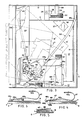
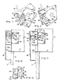
- Figure 1 is a sectional, side elevational view showing a top lid or cover for the vending machine swung to "up" position in order to illustrate various parts of the dispensing mechanism which are supported by the cover, the side door being shown in the "swung-down" position in chain lines;
- Figure 2 is a similar fragmentary side elevational view on an enlarged scale, with the cover however being shown in the "swung-down" position, and, for the sake of convenience, only a single newspaper being shown on the stack supporting elevator platform;
- Figure 3 is a top, sectional plan view, taken on the line III-III of Figure 2, with the chain lines indicating advanced positions of the newspaper being dispensed and the claw which assists in moving the newspaper out the vending slot;
- Figure 4 is a fragmentary, elevational view, taken on the line IV-IV of Figure 3 and showing the dispensing claw in its "ready" position, prior to the time the access door has been unlatched and swung outwardly to operate the dispensing claw;
- Figure 5 is a similar, fragmentary view showing the dispensing claw in a position in which it has engaged the end of the top-most newspaper in the stack;
- Figure 6 is a view similar to Figures 4 and 5, showing the claw in a position in which it is momentarily halted on the return of the access door, in order to permit the access door to be locked before the dispensing claw is moved over to the Figure 4 "ready" position;
- Figure 7 is an enlarged, top plan view showing relative positions of the cable driven plate and the dispensing claw mounting plate at a time when the access door is being returned toward locked position, the chain lines indicating an advanced position of the parts taken on the line VII-VII of Figure 8;
- Figure 8 is a fragmentary, side elevational view thereof;
- Figure 9 is a similar plan view, but showing a different relative position of the cable driven plate and the claw mounting plate, and illustrating the time delay slot which keeps the dispensing claw in the Figure 6 position until the access door is again locked in closed position;
- Figure 10 is a fragmentary, enlarged, sectional, side elevational view illustrating the position of the access door locking parts when the door is in fully closed position;
- Figure 11 is a similar view showing the access door in the act of opening with a coin in a position which permits the locking parts to disengage so that the access door can be swung to open position; and
- Figure 12 is a top plan view of the latch plate which is mounted on the access door.
- Referring to Figures 1-12, it is to be understood that the mechanism described comprises a second embodiment of conversion mechanism for converting a vending machine in which there is free access to the stack of newspapers to a vending machine in which a single newspaper is dispensed with opening of the access door presently included in free access vending machines.
- Typical vending machines of this character which are to be converted are disclosed in United States patent Nos. 3,265,177 and 4,106,609. Such vending machines, as disclosed in Figures 1-12 to which the entire following description relates, comprise a rectilinear housing H with front and
rear walls 10 and 11,side walls 12, and abottom wall 13. The open upper end of the housing H is closed by a lid or cover L which is hinged as at 14 to one of theside walls 12. Cover L, as shown, is provided with arear wall 15,side walls 16, and atop wall 17. - Hingedly connected to the
front wall 10 at 18, is the usual access door, generally designated D, which comprises anouter frame 19 mounting a centrally disposedtransparent plate 20. Theframe 19 comprises tubular elements with inner walls 19a andmarginal walls 19b which, in the conventional manner, provide a space S behind thetransparent panel 20 within which a "display" newspaper DN may be displayed. Torsion springs 21, with aleg 21a trapped bydoor bracket 21b, and aleg 21c trapped by ahousing bracket 21d, have sufficient power to return door D to the closed position. - Previously, the stack of newspapers simply rested on a shelf and the entire stack could be removed once the door D was unlocked and swung outwardly to the D' position shown in Figure 1. In the conversion process, a
panel 22 is secured to thefront wall 10 and has an inset portion 22a which extends upwardly to cover most of the access opening formerly available when the door D was swung to the D' position. It is to this wall portion 22a that the display newspaper DN is releasably secured as by a U-shaped retainingwire 23 secured to wall 22a. As in the normal operation of such vending machines, when all of the newspapers have been dispensed from the stack S, the remaining newspaper DN can be taken by the last user of the vending machine. - It is to be observed that the panel wall portion 22a terminates in a
top wall 22b (Figure 2) spaced downwardly from the upper end of the door D, when the door D is in closed position. Secured to covertop 17 is a frontupper wall panel 23 having an inwardly extendinglower wall 24, which, together with thewall 22b, provides a newspaper dispensing slot O of such size as to permit the dispensing of single newspapers of varying thickness (in the daily to Sunday size) without permitting hand access through the slot O to someone who is attempting to remove more than a single newspaper. - Also to be mounted within the vending machine housing, during the conversion process, is an elevator platform E for supporting the stack S of newspapers which formerly was supported on the housing bottom wall. The elevator E includes
dependent clevis members 25 which are mounted for vertical travel along fixedguide rods 26 secured at each side of the housing H. At each side of the housing H, (see Figure 3) apulley 27, rotatably mounted on ashaft 28 journaled in abearing 29, is provided for supporting acoil spring 30 which is secured to alug portion 25a on each of themembers 25. At its other end, eachcoil spring 30, which is trained around one of thepulleys 27, is secured to amount 30a fixed to theplatform 13. As indicated earlier, the purpose ofsprings 30 is to exert a uniform pressure on the elevator E to constantly urge it upwardly and keep the topmost newspaper N in the stack in dispensable position opposite slot O. - In order to confine the stack S of newspapers, and keep them in a position of vertical alignment, a
back guide plate 31 is fixed to the housing wall 11. Also tending to maintain the alignment of the stack of newspapers N, and to hold the one corner of the topmost newspaper from raising, is aroller 32, rotatably mounted on apin 33 supported by aclevis 34 which itself is mounted for rotation about a vertically extendingpin 35. Theclevis 34 has anupper web 34a, rotatably received against asupport pad 36 carried by a resilientleaf spring member 37 which extends angularly from abracket 38 fixed to covertop wall 17.Roller 32 thus can swivel when the newspaper N is being dispensed. - Provided to engage the diagonally opposite corner of the topmost newspaper N (see Figure 2) in the stack S, is a
roller 39, mounted for rotation on apin 40 supported by aleg 41 which depends from a clawmounting dispensing arm 42. Thearm 42 is fixed to a pin 43 (Fig. 3) which is mounted for pivotal movement in an opening 44, provided in afitting 45 fixed to thetop wall 17 of cover L bybolts 46. Thearm 42 is provided with an extendingportion 42a to which a generally C-shaped leaf spring 47 is secured, as perhaps best illustrated in Figure 11. Theresilient leaf spring 47 has anewspaper engaging claw 48 secured on its free end as shown.Claw 48 is formed with a laterally extendinghook portion 48a, having a beveledterminal edge 48b, such that thehook 48a can engage between the ends of the separate folded sections x of the newspaper, which are open in the sense that thehook 48a can be moved between them. - It is to be understood that the
roller 39 functions as a fulcrum when theclaw 48 is swung in the manner illustrated in the chain lines in Figure 3 outwardly through substantially a 90° arc to a position in which its one end edge extends out slot O and can be grasped by a customer. - Advanced positions of the newspaper, as it is being swung outwardly, are shown at N' and N'' and advanced positions of the claw C are shown at C', C'', and C'''.
Guides 49 may be provided on theside walls 12. So that they will not engage with the paper and in any way affect the return of the mechanism, the corners ofclaw plate 48 are bent upwardly as shown at 48c. - While, as will become apparent,
arm 42 is moved in the dispensing operation by the act of moving the door D to open position, and is also returned by the closing of door D,return spring 50 is also provided for a purpose to be later described. Thereturn spring 50 is fixedly connected to thearm 42 at 51, and fixedly connected to theplate 23 at 52. - Mounted for pivotal movement on
pin 43, and separated from thearm 42 by abearing 53, is adrive plate 54 which is connected by a cable assembly, generally designated 55, to the access door D. Cableassembly 55 includes anouter sheath member 55a withend fittings 55a'. Acable 55b passing throughmember 55a andfittings 55a' is mounted for movement when door D is swung open and returned. Thesheath 55a can be adjustably secured by abracket 56 to thecover top wall 17, as shown in Figure 1, and to abracket 57 secured to the oneside wall 12. A fitting 55c (Fig. 8) fixed tocable 55b is pinned toplate 54 at 55d, and, at its opposite end,cable 55b has a fitting 55e which is pinned as at 55f to anangular bracket 56 which is fixed to door D and extends inwardly therefrom. When door D is swung outwardly,cable 55b swings theplate 54 in a counterclockwise direction in Figure 3. Provided in plate 54 (see Figures 7 and 9) is acurvilinear recess 58 which receives and traps apin 59 which extends upwardly fromarm 42. Thus, whenplate 54 is swung counterclockwisely during the dispensing operation, thepin 59 will also cause thearm 42 and dispensing claw C to be driven counterclockwisely aboutpivot 43. - After the dispensing operation has taken place and the topmost newspaper N has been pulled from the stack by the customer, door D is swung upwardly which causes
cable 55b to swingplate 54 in the return, clockwise direction. At thesame time spring 50 is returningarm 42 in a clockwise direction, so thatarm 42 andplate 54 move in unison. - Provided on a flatted
side 45a of fitting 45 is aplate 60, shown particularly in Figures 3 and 8, which is mounted on theface 45a by apivot pin 61 for movement in a vertical plane between the positions shown in Figure 8 and Figure 2. Atorsion spring 62, provided onpin 61, has a vertically upwardly extendingarm 62a which extends into engagement with thetop wall 17 of cover L. It also has a laterally extendingarm 62b which extends to overlie a projectingleg 60a provided on theplate 60, which is at the level of the top ofpin 59, when the parts are in the normal Figure 8 position. - The
spring arm 62b normally tends to force theleg 60a to the Figure 8 position, but, as will presently be described, theplate 60 can be forced upwardly to the Figure 2 position. Provided on theplate 54 to cam theplate 60 upwardly, is acam pin 63 which, in its path of movement, is adapted to engage a projectingextension 60b provided onplate 60. The manner in which these parts cooperate to provide a lost motion operation, and a delay forclaw 48 in its return to dispensing position, will presently be described. - Referring now more particularly to Figures 10 and 11, we have illustrated conventional door-locking mechanism, and it is to be understood that various door-locking mechanisms of a conventional nature such as shown, for example, in the following U. S. patents 4,037,701; 2,984,326; 3,174,608; 3,125,247; 3,265,177; 3,403,765; 3,464,530; 3,738,466; 3,882,984; 3,496,848; and 4,000,799 may be used. For purposes of the present description to disclose only a typical locking mechanism, we have shown the usual coin box B mounted on the
top wall 17 of cover L. Fixed to the upper end of door D is a latching extension box generally designated 65 which includes outer wall 65a andside walls 65b. It will be observed thatslots 66 are cut in theside walls 65b to receive the extending front edge of thewall 17 when the door D is in locked position (see Figure 10). - Mounted on the front of the coin box B to fit within the
panel 65 when the door D is in locked position, is a box-like projection 67. Coin box B also mounts theusual lock plate 68 which includes the lockingrecess 69 which is open at the front ofplate 68. Lockingrecess 69 has a lower marginal wall 69a, anupper ramp wall 69b, and a verticallock wall portion 69c. Provision is made within the coin box mechanism B for channeling acoin 70, shown in chain lines, to a position in which theusual abutment member 71 holds thecoin 70 during the unlocking operation. Afterward thecoin 70 is moved to the coin receptacle in the usual manner. - Provided on the interior of the
housing 65 isbracket 72 fixed to the walls 65a, and pivotally mounted onbracket 72 islatch plate 73. Thelatch plate 73 has dependent ears 73a, which are rotatably received on apin 74 mounted by the inwardly projecting portions 72a ofplate 72. Atorsion spring 75 has an arm 75a which hooks under aretainer wall 72b provided onbracket 72, and an extendingarm 75b which bears on the forwardly projecting end oflatch plate 73 and normally maintains it in the up position in which it is shown in Figure 10. - Provided on the front end of the
latch plate 73 are a pair of spaced apart upwardlybent cam ears 77 which are in position to be vertically aligned with a pair of coin chutes, one of which may be used for daily papers and the other for Sunday papers, for instance. Intermediate theears 77 is an opening 78a which defines alatch bar 78 formed in thelatch 73. When the door D is in the extreme closed position, the parts are in the Figure 10 location. Assuming thatcoin 70 is fed down into position over one of thecamming ears 77, and door D is attempted to be swung outwardly,wall 78 is forced upwardly by thespring 75 to ride forwardly alongramp surface 69. It can go only until it engagesvertical lock surface 69c. If, however, acoin 70 is inserted to the position shown when door D is moved outwardly by the customer,latch plate 73 is forced downwardly becausecoin 70 pushes one of thecamming ears 77 downwardly, and thelock wall 78 can be moved beyond thelock surface 69c. When the door D is returned bysprings 21 to closed position,latch plate 73 automatically is relatched,latch bar 78 engaging acam surface 68d onplate 68 and being forced downwardly to assume the Figure 10 position. The unlatching operation described is conventional, and need not be further illustrated or described. - In operation, and assuming that the
coin 70 is in the position shown and door D will delatch when it is swung outwardly, it is to be understood that the parts are in the Figures 3 and 4 "ready" position in whichplate 60 is cammed upwardly. As the door D is opened, andcable 55b is moved to the 55' position shown in chain lines in Figure 1, driveplate 54 is swung counterclockwisely (Figure 3) and, because of the engagement of thepin 59 with the marginal wall ofslot 58, theclaw mounting plate 42a will also be moved counterclockwisely.Claw hook 48a will be moved from the Figure 11 position to the Figure 5 position, and enter in between the folds of the topmost newspaper N in the stack S. Asarm 42 andplate 54 move counterclockwisely, thecam lug 63 will be removed from thelatch extension 60b so thatlatch plate 60 immediately swings down to the Figure 8 position, ready for the part which it must play in delaying the movement of the claw C on the return of the door D. - The various positions of the claw C and the topmost newspaper during counterclockwise movement of
plate 54 andarm 42 are disclosed in Figure 3 and have previously been mentioned. When the door D has been swung to the horizontal position in which it is shown in chain lines at D' in Figure 1, the newspaper will have been swung to or past the N'' position in which it is shown in Figure 4, and will be in a position of projection out the slot O so that it can be grasped by the customer and pulled out the remainder of the way. - When the customer then releases door D, the torsion springs 100 on the hinge pins 18 cause the door to be swung inwardly thus moving
cable 55b in a direction to causeplate 54 to be driven in the clockwise direction. Thereturn spring 50 will, at the same time,cause arm 42 to move in unison with theplate 54. This movement clockwisely in unison continues untilpost 59 on thearm 42 comes into engagement with thelug 60a, which is in the Figure 8 position as previously indicated. At this point, further clockwise movement of theclaw mounting arm 42 is arrested by thelatch 60, while thedrive plate 54 can continue to move clockwisely becauserecess 58 can move relative to pin 59 to the Figure 9 position of the parts. The purpose of arresting the movement ofarm 42 and claw C so that the claw C is at rest for a short time in the Figure 6 position is so that door D can be latched in position before the claw C is permitted to snap clockwisely over to the dispensing position. - If the door D were not locked before the claw C reached the lowered Figure 4 position in which it could dispense another paper, it would be possible for a customer to move the door to almost closed position, and then swing it downwardly again and dispense a second newspaper without having paid for it. After the short time delay provided by the relative clockwise movement of
drive plate 54 whenarm 42 remains stationary,cam 63 has moved withplate 54 to a position where it engages theprojection 60b onlatch plate 60. Further movement ofplate 54 clockwisely will cause theplate 60 to be cammed upwardly to the Figure 2 position against the force exerted bytorsion spring 62, at which time plate 64 will be abruptly released to snap further clockwisely because of the contraction ofspring 50 to normal position. Claw C thus moves almost instantaneously (at a time whendoor lock latch 73 has moved itslatch bar 78 beyondvertical wall 69c) from the Figure 6 position over to the Figure 4 position. - To support the cover L in open position when desired, so that a stack of newspapers a may be loaded to the elevator platform E, a
brace bar 76 is supported by acrossbar 77 provided on the cover L. Thebrace bar 76 is adapted to be received by anenlarged sleeve 78 fixed to the housing rear wall 11. A turned uplower end 76a ofbar 76 engages under thesleeve 78 to prevent the cover from being swung upwardly beyond a vertical position.
Claims (4)
- A coin operated newspaper and like article vending machine for dispensing articles on a one-at-a-time basis, comprising:a) a housing (H) forming a cabinet for containing newspapers and like articles to be vended;b) a door (D) hinged on one side of the cabinet;c) coin operated lock mechanism (73, 69c) automatically reengagable to lock the door as the door is returned to closed position;d) partition means (23, 24, 22b) incorporated with the housing as a wall thereof situated behind the door and providing a dispensing slot (O) behind the door for passing one article at a time;e) mechanism (E, 27, 30) for assuring the delivery of newspaper successively to a location opposite the dispensing slot;f) newspaper dispensing elements (22, 47, C) movable in an arcuate path of travel in a generally horizontal plane between a dispensing position and a projection position, said newspaper dispensing elements being actuable to engage and pivotally move the newspaper through an angle approaching 90 degrees to a position partly out of the dispensing slot;g) linkage mechanism (55, 55b, 56, 54, 59, 50) connecting the door and the newspaper dispensing elements, operable when the door is swung, to move the newspaper at least partly out of the dispensing slot and to move the newspaper dispensing elements in the return direction with closing of the door;characterized byh) means (60, 60a, 63, 60b) for delaying return of the newspaper dispensing elements to the dispensing position pending return of the door to closed position to prevent the next successive newspaper from being dispensed before the lock mechanism is reengaged.
- A machine according claim 1 characterized by means (50) operating independently of the closing movement of the door (D) for moving the newspaper dispensing elements (42, 47, C) to the dispensing position after the door is returned to closed position and the lock mechanism (73, 69c) is reengaged.
- A method of converting a newspaper and like article vending machine comprising a housing (H) with an access door (D) in a side wall thereof which can be moved to open position, and a coin operated lock mechanism (73, 69c) which automatically locks when the door is moved to closed position, and which can be unlocked when proper coins are fed to the locking mechanism, including the steps of:a) biasing an elevator platform (E) within the housing (H) opposite the access door (D) to support a stack (S) of newspapers (N) such that the topmost is at a predetermined level;b) partitioning the space behind the door off from access via the door except for a dispensing slot (O) of a size to dispense a single newspaper from the upper end of the housing at said level;c) engaging the topmost newspaper with a newspaper dispensing elements (42, 47, C) connected with the access door such thatcharacterized by- an opening movement of the door will move the newspaper dispensing elements from a dispensing position to a projection position in a path of travel to drive the newspaper partly out of said dispensing slot to a position where it can be grasped and pulled the rest of the way out by the customer,- and moving the access door in a return direction will move the newspaper dispensing elements in a return direction,d) providing means (60, 60a, 63, 60b) for delaying return of the newspaper dispensing elements to the dispensing position pending return of the door to closed position to prevent the next successive newspaper from being dispensed before the lock mechanism is reengaged.
- A method of dispensing a newspaper (N) or like article from a housing (H) having an access door (D) in a side wall thereof which can be moved to open position, partition means (23, 24, 22b) behind the door providing a dispensing slot (O) near its upper end, an elevator (E) including a platform for supporting a stack (S) of horizontally disposed newspapers (N) with the uppermost opposite said dispensing slot, a newspaper dispensing elements (42, 47, C) for engaging the topmost newspaper connected with said access door such as to drive the newspaper partly out of said dispensing slot when the door is moved toward open position, and a coin operated lock mechanism (73, 69c) which automatically locks the door when the door is moved to closed position, and which can be unlocked when proper coins are inserted; comprising the steps of:a) by moving the door to open position, moving the newspaper dispensing elements (42, 47, C) in an arcuate path of travel in a generally horizontal plane from a dispensing position to a projection position thus pivoting the newspaper through an angle approaching 90 degrees;b) pulling the newspaper from the dispensing slot (O); andc) restoring the door to closed position and locking the door once again;characterized byd) delaying a return of the newspaper dispensing elements in the dispensing position upon restoration of the door to closed position and reengaging the lock mechanism.
Applications Claiming Priority (4)
| Application Number | Priority Date | Filing Date | Title |
|---|---|---|---|
| US06/613,641 US4558803A (en) | 1984-05-24 | 1984-05-24 | Mechanism for converting stack access newspaper vending machines and the like to machines for dispensing products one at a time |
| US06/635,664 US4566608A (en) | 1984-05-24 | 1984-07-30 | System for converting stack access newspaper vending machines and the like to apparatus for dispensing products one at a time |
| US635664 | 1984-07-30 | ||
| US613641 | 2003-07-02 |
Publications (3)
| Publication Number | Publication Date |
|---|---|
| EP0165504A2 EP0165504A2 (en) | 1985-12-27 |
| EP0165504A3 EP0165504A3 (en) | 1988-03-23 |
| EP0165504B1 true EP0165504B1 (en) | 1992-02-26 |
Family
ID=27087068
Family Applications (1)
| Application Number | Title | Priority Date | Filing Date |
|---|---|---|---|
| EP85106392A Expired - Lifetime EP0165504B1 (en) | 1984-05-24 | 1985-05-23 | System for converting stack access newspaper vending machines and the like to apparatus for dispensing products one at a time |
Country Status (4)
| Country | Link |
|---|---|
| US (1) | US4566608A (en) |
| EP (1) | EP0165504B1 (en) |
| CA (1) | CA1239126A (en) |
| DE (1) | DE3585418D1 (en) |
Families Citing this family (14)
| Publication number | Priority date | Publication date | Assignee | Title |
|---|---|---|---|---|
| GB2207910B (en) * | 1987-07-28 | 1991-02-27 | Journomat Ag | Vending machine for newspapers or periodicals |
| US5199599A (en) * | 1992-06-19 | 1993-04-06 | Shade Michael W | Apparatus for dispensing articles |
| DK99792D0 (en) * | 1992-08-07 | 1992-08-07 | Berlingske Dagblade As | PROCEDURE AND APPARATUS FOR SELECTING ARTICLES FROM A STACK |
| US5363987A (en) * | 1993-02-17 | 1994-11-15 | Seven, Ltd. | Newspaper vending unit |
| ATE475160T1 (en) * | 1999-06-16 | 2010-08-15 | Thomas F Masek | Vending machine for selling newspapers per piece |
| US6644503B2 (en) | 2001-12-04 | 2003-11-11 | John Peterson | Single publication vending device |
| KR100425866B1 (en) * | 2001-12-29 | 2004-04-01 | 엘지엔시스(주) | Apparatus for locking door in automatic teller machine |
| JP4018437B2 (en) * | 2002-04-30 | 2007-12-05 | サンデン株式会社 | Madler unloader |
| CA2609329A1 (en) * | 2005-05-25 | 2006-11-30 | Munroe Chirnomas | Article dispenser |
| US11297984B2 (en) | 2006-10-31 | 2022-04-12 | Gpcp Ip Holdings Llc | Automatic napkin dispenser |
| FR2907654B1 (en) * | 2006-10-31 | 2010-01-29 | Georgia Pacific France | PROCESS, MANUFACTURING DEVICE AND ASSOCIATED ROLLS FORMED OF CUTTING SHEETS AND ALTERNATE PREDECOUPLES |
| US10383489B2 (en) | 2012-02-10 | 2019-08-20 | Gpcp Ip Holdings Llc | Automatic napkin dispenser |
| US9604811B2 (en) | 2013-10-01 | 2017-03-28 | Georgia-Pacific Consumer Products Lp | Automatic paper product dispenser with data collection and method |
| CN110494070A (en) | 2017-05-10 | 2019-11-22 | Gpcp知识产权控股有限责任公司 | Automatic paper product distributor and associated method |
Family Cites Families (7)
| Publication number | Priority date | Publication date | Assignee | Title |
|---|---|---|---|---|
| GB763971A (en) * | 1900-01-01 | |||
| US3831809A (en) * | 1973-05-18 | 1974-08-27 | K Knickerbocker | Single-vend dispensing machine |
| US4174047A (en) * | 1978-03-06 | 1979-11-13 | 3-in-1, Inc. | Vending machine for newspapers and the like |
| US4331261A (en) * | 1980-08-29 | 1982-05-25 | Brown Kelly G S | Retrofit single-newspaper security dispenser |
| US4418836A (en) * | 1981-07-23 | 1983-12-06 | Christian Donald K | Vending machine for newspaper, magazines and the like |
| US4569461A (en) * | 1982-07-30 | 1986-02-11 | Berkley-Small, Inc. | Single copy newspaper dispensing machine |
| US4501379A (en) * | 1983-06-20 | 1985-02-26 | William Halone | Newspaper dispensing apparatus |
-
1984
- 1984-07-30 US US06/635,664 patent/US4566608A/en not_active Expired - Fee Related
-
1985
- 1985-05-23 DE DE8585106392T patent/DE3585418D1/en not_active Expired - Fee Related
- 1985-05-23 EP EP85106392A patent/EP0165504B1/en not_active Expired - Lifetime
- 1985-05-24 CA CA000482373A patent/CA1239126A/en not_active Expired
Also Published As
| Publication number | Publication date |
|---|---|
| EP0165504A2 (en) | 1985-12-27 |
| CA1239126A (en) | 1988-07-12 |
| EP0165504A3 (en) | 1988-03-23 |
| DE3585418D1 (en) | 1992-04-02 |
| US4566608A (en) | 1986-01-28 |
Similar Documents
| Publication | Publication Date | Title |
|---|---|---|
| EP0165504B1 (en) | System for converting stack access newspaper vending machines and the like to apparatus for dispensing products one at a time | |
| EP0871150B1 (en) | Card dispensing cassette | |
| EP1230138B1 (en) | Single vend newspaper vending machine | |
| US4251009A (en) | Security door assembly for an automatic document dispensing device | |
| EP0105914A1 (en) | Vertical article dispenser | |
| US4962867A (en) | Auxiliary article dispenser for vending machines | |
| US4296873A (en) | Automatic vending arrangement | |
| CA1228057A (en) | Coin operated dispensers for dispensing horizontally disposed articles such as newspapers from the upper end of a stack | |
| CA1107695A (en) | Trap door for vending machine | |
| US6003725A (en) | Single vend newspaper vending machine | |
| US3958821A (en) | Door operating assembly for merchandising machine or the like | |
| US4258861A (en) | Single-paper vending apparatus | |
| US5248060A (en) | Theft deterrent device for newspaper dispensing machines | |
| US4530444A (en) | Separation device for single copy newspaper vendor | |
| US4319695A (en) | Vendor for flat articles | |
| US5209336A (en) | Newspaper vending machine | |
| US5996840A (en) | Newspaper and magazine dispensing machine | |
| US3180518A (en) | Mechanical vendor for articles | |
| US3777929A (en) | Newspaper vendor | |
| US6112941A (en) | Single vend newspaper vending machine | |
| US4175989A (en) | Newspaper vending machine | |
| US5368189A (en) | Vending machine for newspapers and like articles | |
| US4428503A (en) | Vending machine for insuring the dispensing of newspapers and the like one at a time | |
| US5000346A (en) | Method and apparatus for dispensing newspapers | |
| US4558803A (en) | Mechanism for converting stack access newspaper vending machines and the like to machines for dispensing products one at a time |
Legal Events
| Date | Code | Title | Description |
|---|---|---|---|
| PUAI | Public reference made under article 153(3) epc to a published international application that has entered the european phase |
Free format text: ORIGINAL CODE: 0009012 |
|
| AK | Designated contracting states |
Designated state(s): DE FR GB |
|
| PUAL | Search report despatched |
Free format text: ORIGINAL CODE: 0009013 |
|
| AK | Designated contracting states |
Kind code of ref document: A3 Designated state(s): DE FR GB |
|
| 17P | Request for examination filed |
Effective date: 19880920 |
|
| 17Q | First examination report despatched |
Effective date: 19900720 |
|
| GRAA | (expected) grant |
Free format text: ORIGINAL CODE: 0009210 |
|
| AK | Designated contracting states |
Kind code of ref document: B1 Designated state(s): DE FR GB |
|
| REF | Corresponds to: |
Ref document number: 3585418 Country of ref document: DE Date of ref document: 19920402 |
|
| ET | Fr: translation filed | ||
| PLBE | No opposition filed within time limit |
Free format text: ORIGINAL CODE: 0009261 |
|
| STAA | Information on the status of an ep patent application or granted ep patent |
Free format text: STATUS: NO OPPOSITION FILED WITHIN TIME LIMIT |
|
| 26N | No opposition filed | ||
| PGFP | Annual fee paid to national office [announced via postgrant information from national office to epo] |
Ref country code: GB Payment date: 19950515 Year of fee payment: 11 |
|
| PGFP | Annual fee paid to national office [announced via postgrant information from national office to epo] |
Ref country code: FR Payment date: 19950529 Year of fee payment: 11 |
|
| PGFP | Annual fee paid to national office [announced via postgrant information from national office to epo] |
Ref country code: DE Payment date: 19950727 Year of fee payment: 11 |
|
| PG25 | Lapsed in a contracting state [announced via postgrant information from national office to epo] |
Ref country code: GB Effective date: 19960523 |
|
| GBPC | Gb: european patent ceased through non-payment of renewal fee |
Effective date: 19960523 |
|
| PG25 | Lapsed in a contracting state [announced via postgrant information from national office to epo] |
Ref country code: FR Effective date: 19970131 |
|
| PG25 | Lapsed in a contracting state [announced via postgrant information from national office to epo] |
Ref country code: DE Effective date: 19970201 |
|
| REG | Reference to a national code |
Ref country code: FR Ref legal event code: ST |