EP0164185B1 - Milking claw - Google Patents
Milking claw Download PDFInfo
- Publication number
- EP0164185B1 EP0164185B1 EP85302241A EP85302241A EP0164185B1 EP 0164185 B1 EP0164185 B1 EP 0164185B1 EP 85302241 A EP85302241 A EP 85302241A EP 85302241 A EP85302241 A EP 85302241A EP 0164185 B1 EP0164185 B1 EP 0164185B1
- Authority
- EP
- European Patent Office
- Prior art keywords
- milk
- bowl
- cover
- outlet
- nipples
- Prior art date
- Legal status (The legal status is an assumption and is not a legal conclusion. Google has not performed a legal analysis and makes no representation as to the accuracy of the status listed.)
- Expired - Lifetime
Links
- 210000000078 claw Anatomy 0.000 title claims description 26
- 239000008267 milk Substances 0.000 claims description 46
- 210000004080 milk Anatomy 0.000 claims description 46
- 235000013336 milk Nutrition 0.000 claims description 46
- 210000002445 nipple Anatomy 0.000 claims description 44
- 238000005187 foaming Methods 0.000 description 3
- 229920003023 plastic Polymers 0.000 description 3
- 239000004033 plastic Substances 0.000 description 3
- 238000011176 pooling Methods 0.000 description 2
- 230000010349 pulsation Effects 0.000 description 2
- 238000006243 chemical reaction Methods 0.000 description 1
- 230000003247 decreasing effect Effects 0.000 description 1
- 239000000796 flavoring agent Substances 0.000 description 1
- 235000019634 flavors Nutrition 0.000 description 1
- 239000006260 foam Substances 0.000 description 1
- 230000005484 gravity Effects 0.000 description 1
- 238000010348 incorporation Methods 0.000 description 1
- 208000015181 infectious disease Diseases 0.000 description 1
- 230000001788 irregular Effects 0.000 description 1
- 208000004396 mastitis Diseases 0.000 description 1
- 230000003647 oxidation Effects 0.000 description 1
- 238000007254 oxidation reaction Methods 0.000 description 1
Images

Classifications
-
- A—HUMAN NECESSITIES
- A01—AGRICULTURE; FORESTRY; ANIMAL HUSBANDRY; HUNTING; TRAPPING; FISHING
- A01J—MANUFACTURE OF DAIRY PRODUCTS
- A01J5/00—Milking machines or devices
- A01J5/04—Milking machines or devices with pneumatic manipulation of teats
- A01J5/041—Milk claw
Definitions
- the present invention relates to a milking claw comprising a closed container having four inlet nipples, each being adapted to receive milk from a respective teat cup, and a single outlet.
- DE-A-3,140,543 discloses a known milking claw comprising a closed container having four inlet nipples each adapted to receive milk from a respective teat cup.
- the container comprises a bowl having a single outlet which is positioned below the four inlet nipples and a cover meeting the bowl at a generally circular connection.
- the cover has a frusto-conical side wall with the lower, larger diameter portion connected to the bowl, and each inlet nipple extending upwardly and outwardly relative to the side wall of the cover and generally tangential to said side wall so that incoming milk is downwardly directed and introduced to the interior of the cover in a tangential manner.
- a milking claw as described in DE-A-3,140,543 suffers from the disadvantage that the inlet nipples are so positioned that there could occur a flow of milk from one nipple to another.
- the claw can cause pooling of the milk in the claw, that is the milk is slowed down causing loss of kinetic energy or failure to drain completely, causing subsequent spillage of milk. This results in requiring a higher vacuum to move the milk from the claw. That requires more energy and also causes increased and irregular vacuum pulsation on the teats which renders the teats more prone to mastitis.
- This invention seeks to solve the shortcomings of the prior art.
- the milk claw of the present invention is characterised in that said inlet nipples are connected to an upper region of the cover and thatthe cover is of sufficient height that the incoming, downwardly and tangentially directed milk swirls down and around the sloping inside of said cover on a path having an increasing diameter causing the milk velocity to decrease, whereby any tendency of the milk to flow back to said nipples from said single outlet requires that the milk be both lifted and accelerated.
- the bowl has a downwardly inclined spiral flow path of increasing cross-sectional area leading to a radially disposed outlet.
- a dam separates the start of the downwardly spiraled path and the outlet.
- the dam is generally parallel to the outlet axis.
- the flow path and dam co-operate to direct the incoming milk to the outlet in a very efficient manner conserving the kinetic energy of the incoming milk.
- the outlet is at the low point of the flow path so the claw can be tilted substantially without affecting the continuity of flow.
- the claw will normally not be tilted so much that milk is pooled rather than flowing continuously to the outlet. Therefore, the vacuum requirements are minimised, pulsation of the milking vacuum is reduced, and spillage of milk from the claw is minimised.
- a further preferred feature is the radial disposition of the outlet leading from the above mentioned spiral flow path. Should there be a blow-back of milk from the outlet, the milk enters the bowl through the outlet. The kinetic energy of this milk is dissipated as it is directed generally upward and into a path of decreasing cross-section, limiting its ability to reach any of the inlets. Any blow back in the outlet is unlikely to reach any inlet. The possibility of blow-back is further reduced by the frusto-conical geometry of the cover, since any milk moving in a circumferential path within the cover tends to remain in or move to the lower portion of the cover because of the combined actions of gravity and the downward component of the reaction force of the wall on the milk.
- the radial disposition of the outlet serves to balance the forces on the claw due to the weight of the outlet hose so the weight is not borne by two teats only.
- Still another preferred feature is the arrangement of the tangential downwardly inclined inlet nipples in a generally rectangular pattern around the cover. This permits the use of plastics hoses or similar of substantially equal length while accommodating the fact that a cow's teats are arranged in a generally rectangular pattern. This equalises the weight on the teats and is much betterforthecows. Claws such as that described in US-A-4,253,419, mentioned above, arrange the nipples in a square which will inherently unbalance the loads on the teats.
- the milking claw 10 includes a bowl 12 and a cover 14 which has the general shape of a frustrum of a cone with the large diameter of the frustrum being connected to the bowl with the gasket 16 interposed between the bottom 18 of the cover and the internal seat 20 provided at the top of the bowl.
- the gasket 16 has an inturned lip which lies between the cover and the bowl and is compressed as the connector 22 is tightened.
- the connector has a threaded end 24 which extends through the central boss 25 of the cover and threads into a threaded sleeve 26 fixed in the central boss 28 in the bowl with gasket 27 captured between boss 25 and boss 28.
- the upper end of the connector 22 is provided with a washer 30 welded to the connector to overlie the loose washer 32 and gasket 34 so as to compress the gasket 34 against the top of the frusto-conical cover 14 when the connector is tightened.
- the upper end of the connector is shaped to provide a hanging eye 36.
- the upper portion of the frusto-conical cover 14 is provided with four inlet nipples 38, 40, 42, 44. Each nipple is generally tangential to the wall of the cover 14 and is downwardly inclined. With this arrangement, milk entering the nipples will be started downwardly on a path hugging the wall of the frusto-conical cover and cause the milk to swirl about the axis of the cover and bowl rather than dropping into the bowl and foaming. This swirling action in a downward and radially expanding path, coupled with the downward spiral of increasing cross-section in the bowl 12, virtually precludes the possibility of milk being blown back into a nipple other than the one from which the milk came.
- inlet 44 is above and in the same vertical plane as the centre of the discharge fitting or outlet 46 leading radially out of the bowl.
- the outlet leads from the low point in the bowl.
- the inlet nipples 38, 40 are closer to each other than they are to inlet nipples 42,44.
- the inlets intersect the frusto-conical cover generally in a rectangular arrangement as can be seen in dotted lines in Fig. 3.
- This generally rectangular configuration accommodates the natural arrangement of a cow's teats. They are not arranged in a square pattern, but they are, instead, in a rectangular pattern. This, therefore, permits the hoses connecting the teat cups to the inlets to the milking claw to be of equal length to assure equal weight on each of the four teats of the cow rather than causing unequal weight on the teats as is common in the prior art where the nipples are arranged in a square pattern.
- the interior of the bowl 12 is molded to accommodate and provide an extension of the downard swirling action of the milk.
- a dam 48 which runs generally parallel to the outlet 46.
- the dam runs out to the outer wall of the bowl. Looking downwardly on the bowl, the area immediately to the right and in a clockwise direction from the area 50 is relatively shallow and the floor of the bowl sweeps downwardly in a spiral fashion as can be seen clearly in Fig. 2.
- the downwardly spiraling configuration of the bowl provides an increasing cross-sectional area accommodating the increasing volume of milk likely to be in the flow path as the outlet 46 is approached.
- the dam 48 deflects the milk from the low point into the outlet 46.
- the outlet is so low relative to the rest of the floor or bottom of the bowl that pooling is virtually precluded.
- the milk keeps moving continuously from the inlet down through the spiraling path on the interior wall of the cover and into the bowl which guides the milk over a further spiraling path into the outlet.
- the milk is kept in motion and kinetic energy is preserved. Therefore, the amount of energy (vacuum) which needs to be applied to the system is kept at a minimum.
- Orientation of the inlet 44 relative to the outlet 46 is assured by providing the bowl with an upstanding key or lug 52 which engages a corresponding notch 54 in the frusto-conical cover to orient the parts. If other orientations of the outlet to inlet were desired, as for example in the event it were desired to have the outlet directed to the side rather than to the rear of the cow, key or lug 52 could be omitted or relocated. It is thus much easier to change the orientation of the outlet with respect to the cow, and thereby to accommodate varying arrangements at the milking barn, with this claw than with previous designs.
- the bowl is provided with a hanger bracket 56.
- the bowl is molded out of plastics. This makes it possible to obtain the downward spiraled flow path at reasonable cost.
- the cover is clear plastics to allow observation of the milk.
Landscapes
- Life Sciences & Earth Sciences (AREA)
- Animal Husbandry (AREA)
- Environmental Sciences (AREA)
- External Artificial Organs (AREA)
- Dairy Products (AREA)
- Ultra Sonic Daignosis Equipment (AREA)
Description
- The present invention relates to a milking claw comprising a closed container having four inlet nipples, each being adapted to receive milk from a respective teat cup, and a single outlet.
- DE-A-3,140,543 discloses a known milking claw comprising a closed container having four inlet nipples each adapted to receive milk from a respective teat cup. The container comprises a bowl having a single outlet which is positioned below the four inlet nipples and a cover meeting the bowl at a generally circular connection. The cover has a frusto-conical side wall with the lower, larger diameter portion connected to the bowl, and each inlet nipple extending upwardly and outwardly relative to the side wall of the cover and generally tangential to said side wall so that incoming milk is downwardly directed and introduced to the interior of the cover in a tangential manner.
- It is desirable to reduce foaming in the claw because foam, which occurs as a result of the incorporation of air into the milk, causes off- flavours and also may render a downstream meter, if used, inaccurate, which means the production records will be faulty. It is further desirable that any blow back in the discharge line should not be able to cause blow back in the line to a teat cup which could cause 'the teat to be washed or impacted with milk from an infected teat with possible spread of infection. A milking claw as described in DE-A-3,140,543 suffers from the disadvantage that the inlet nipples are so positioned that there could occur a flow of milk from one nipple to another. Also the claw can cause pooling of the milk in the claw, that is the milk is slowed down causing loss of kinetic energy or failure to drain completely, causing subsequent spillage of milk. This results in requiring a higher vacuum to move the milk from the claw. That requires more energy and also causes increased and irregular vacuum pulsation on the teats which renders the teats more prone to mastitis.
- Another known milking claw which suffers from the aforementioned disadvantages is described in US-A-4,253,419.
- This invention seeks to solve the shortcomings of the prior art.
- The milk claw of the present invention is characterised in that said inlet nipples are connected to an upper region of the cover and thatthe cover is of sufficient height that the incoming, downwardly and tangentially directed milk swirls down and around the sloping inside of said cover on a path having an increasing diameter causing the milk velocity to decrease, whereby any tendency of the milk to flow back to said nipples from said single outlet requires that the milk be both lifted and accelerated.
- The downwardly and tangentially arranged inlet nipples lead into the upper portion (small diameter) of the cover. This starts the milk downwardly on a swirling path of increasing diameter. This puts the incoming milk on a path which virtually precludes backing milk into a nipple other than that from which it came. The milk hugs the frusto-conical wall, avoiding free fall which would cause foaming and oxidation.
- Preferably the bowl has a downwardly inclined spiral flow path of increasing cross-sectional area leading to a radially disposed outlet. In a preferred embodiment a dam separates the start of the downwardly spiraled path and the outlet. The dam is generally parallel to the outlet axis. The flow path and dam co-operate to direct the incoming milk to the outlet in a very efficient manner conserving the kinetic energy of the incoming milk. The outlet is at the low point of the flow path so the claw can be tilted substantially without affecting the continuity of flow. The claw will normally not be tilted so much that milk is pooled rather than flowing continuously to the outlet. Therefore, the vacuum requirements are minimised, pulsation of the milking vacuum is reduced, and spillage of milk from the claw is minimised.
- A further preferred feature is the radial disposition of the outlet leading from the above mentioned spiral flow path. Should there be a blow-back of milk from the outlet, the milk enters the bowl through the outlet. The kinetic energy of this milk is dissipated as it is directed generally upward and into a path of decreasing cross-section, limiting its ability to reach any of the inlets. Any blow back in the outlet is unlikely to reach any inlet. The possibility of blow-back is further reduced by the frusto-conical geometry of the cover, since any milk moving in a circumferential path within the cover tends to remain in or move to the lower portion of the cover because of the combined actions of gravity and the downward component of the reaction force of the wall on the milk. The radial disposition of the outlet serves to balance the forces on the claw due to the weight of the outlet hose so the weight is not borne by two teats only.
- Still another preferred feature is the arrangement of the tangential downwardly inclined inlet nipples in a generally rectangular pattern around the cover. This permits the use of plastics hoses or similar of substantially equal length while accommodating the fact that a cow's teats are arranged in a generally rectangular pattern. This equalises the weight on the teats and is much betterforthecows. Claws such as that described in US-A-4,253,419, mentioned above, arrange the nipples in a square which will inherently unbalance the loads on the teats.
- An embodiment of the invention will now be described, by way of example only, with reference to the accompanying diagrammatic drawings, in which:
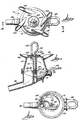
- Fig. 1 is a perspective view from slightly above the claw,
- Fig. 2 is an exploded perspective view from generally the same angle as in Fig. 1.,
- Fig. 3 is a top plan view of the claw,
- Fig. 4 is a vertical section on meandering line 4-4 in Fig. 3., and
- Fig. 5 is a plan view of the bowl of the claw.
- The milking claw 10 includes a
bowl 12 and acover 14 which has the general shape of a frustrum of a cone with the large diameter of the frustrum being connected to the bowl with thegasket 16 interposed between the bottom 18 of the cover and theinternal seat 20 provided at the top of the bowl. Thegasket 16 has an inturned lip which lies between the cover and the bowl and is compressed as theconnector 22 is tightened. It will be noted the connector has a threadedend 24 which extends through thecentral boss 25 of the cover and threads into a threadedsleeve 26 fixed in the central boss 28 in the bowl with gasket 27 captured betweenboss 25 and boss 28. The upper end of theconnector 22 is provided with awasher 30 welded to the connector to overlie theloose washer 32 and gasket 34 so as to compress thegasket 34 against the top of the frusto-conical cover 14 when the connector is tightened. The upper end of the connector is shaped to provide a hangingeye 36. - The upper portion of the frusto-
conical cover 14 is provided with fourinlet nipples cover 14 and is downwardly inclined. With this arrangement, milk entering the nipples will be started downwardly on a path hugging the wall of the frusto-conical cover and cause the milk to swirl about the axis of the cover and bowl rather than dropping into the bowl and foaming. This swirling action in a downward and radially expanding path, coupled with the downward spiral of increasing cross-section in thebowl 12, virtually precludes the possibility of milk being blown back into a nipple other than the one from which the milk came. - It will be noted that the
inlet 44 is above and in the same vertical plane as the centre of the discharge fitting oroutlet 46 leading radially out of the bowl. The outlet leads from the low point in the bowl. - It will be noted that the
inlet nipples nipples - The interior of the
bowl 12 is molded to accommodate and provide an extension of the downard swirling action of the milk. Thus, from the central boss 28 of the bowl there is adam 48 which runs generally parallel to theoutlet 46. The dam runs out to the outer wall of the bowl. Looking downwardly on the bowl, the area immediately to the right and in a clockwise direction from the area 50 is relatively shallow and the floor of the bowl sweeps downwardly in a spiral fashion as can be seen clearly in Fig. 2. Thus, the downwardly spiraling configuration of the bowl provides an increasing cross-sectional area accommodating the increasing volume of milk likely to be in the flow path as theoutlet 46 is approached. Thedam 48 deflects the milk from the low point into theoutlet 46. The outlet is so low relative to the rest of the floor or bottom of the bowl that pooling is virtually precluded. The milk keeps moving continuously from the inlet down through the spiraling path on the interior wall of the cover and into the bowl which guides the milk over a further spiraling path into the outlet. The milk is kept in motion and kinetic energy is preserved. Therefore, the amount of energy (vacuum) which needs to be applied to the system is kept at a minimum. - Orientation of the
inlet 44 relative to theoutlet 46 is assured by providing the bowl with an upstanding key or lug 52 which engages acorresponding notch 54 in the frusto-conical cover to orient the parts. If other orientations of the outlet to inlet were desired, as for example in the event it were desired to have the outlet directed to the side rather than to the rear of the cow, key or lug 52 could be omitted or relocated. It is thus much easier to change the orientation of the outlet with respect to the cow, and thereby to accommodate varying arrangements at the milking barn, with this claw than with previous designs. - The bowl is provided with a
hanger bracket 56. The bowl is molded out of plastics. This makes it possible to obtain the downward spiraled flow path at reasonable cost. Preferably, the cover is clear plastics to allow observation of the milk.
Claims (5)
Applications Claiming Priority (2)
| Application Number | Priority Date | Filing Date | Title |
|---|---|---|---|
| US06/616,115 US4537152A (en) | 1984-06-01 | 1984-06-01 | Milking claw |
| US616115 | 1990-11-20 |
Publications (3)
| Publication Number | Publication Date |
|---|---|
| EP0164185A2 EP0164185A2 (en) | 1985-12-11 |
| EP0164185A3 EP0164185A3 (en) | 1986-11-20 |
| EP0164185B1 true EP0164185B1 (en) | 1990-02-21 |
Family
ID=24468086
Family Applications (1)
| Application Number | Title | Priority Date | Filing Date |
|---|---|---|---|
| EP85302241A Expired - Lifetime EP0164185B1 (en) | 1984-06-01 | 1985-04-01 | Milking claw |
Country Status (13)
| Country | Link |
|---|---|
| US (1) | US4537152A (en) |
| EP (1) | EP0164185B1 (en) |
| JP (1) | JPS6181740A (en) |
| AU (1) | AU564926B2 (en) |
| CA (1) | CA1226845A (en) |
| DE (2) | DE3576064D1 (en) |
| DK (1) | DK168351B1 (en) |
| ES (1) | ES8702771A1 (en) |
| HU (1) | HU192223B (en) |
| IE (1) | IE56434B1 (en) |
| IL (1) | IL75295A (en) |
| NO (1) | NO159331C (en) |
| NZ (1) | NZ211625A (en) |
Cited By (1)
| Publication number | Priority date | Publication date | Assignee | Title |
|---|---|---|---|---|
| RU2675478C1 (en) * | 2015-06-17 | 2018-12-19 | Геа Фарм Текнолоджиз Гмбх | Device of milk separation |
Families Citing this family (35)
| Publication number | Priority date | Publication date | Assignee | Title |
|---|---|---|---|---|
| US4807566A (en) * | 1987-10-05 | 1989-02-28 | Alfa-Laval, Inc. | Milk claw |
| SE461067B (en) * | 1988-05-04 | 1990-01-08 | Alfa Laval Agri Int | claw is |
| US4941433A (en) * | 1988-05-23 | 1990-07-17 | Agri-Automation Company, Ltd. | Milking method and related apparatus |
| US4907535A (en) * | 1988-06-01 | 1990-03-13 | Orion Machinery Co. Ltd. | Milk-claw for milking machines |
| NZ229021A (en) * | 1989-08-10 | 1993-03-26 | Alfa Laval Nz Ltd T A Nu Pulse | Milking machine claw bowl: angled outlet nipple originates from bowl centre |
| US5080041A (en) * | 1990-08-30 | 1992-01-14 | Dec International, Inc. | Pre-curved milk tube |
| US5218924A (en) * | 1992-03-19 | 1993-06-15 | Dec International, Inc. | Milking system with variable pressure source |
| NZ242686A (en) * | 1992-05-11 | 1994-12-22 | Carter Holt Harvey Plastic Pro | Milking claw divided into four chambers to reduce likelihood of cross contamination of animal's quarters |
| US5291853A (en) * | 1993-04-08 | 1994-03-08 | Dec International, Inc. | Top unloaded milking claw |
| US5586518A (en) * | 1995-03-27 | 1996-12-24 | Dec International, Inc. | Milking cluster air fork |
| US5720236A (en) | 1996-01-16 | 1998-02-24 | Dec International, Inc. | Milk meter |
| SE511150C2 (en) * | 1996-02-05 | 1999-08-09 | Alfa Laval Agri Ab | claw |
| AU132523S (en) * | 1997-01-28 | 1997-12-19 | Delaval Holding Ab | Cover for a milking claw |
| US6039001A (en) | 1998-05-19 | 2000-03-21 | Dec International, Inc. | Teatcup liner with desired mouthpiece chamber vacuum |
| US6055931A (en) * | 1998-10-13 | 2000-05-02 | Dec International, Inc. | Clog resistant air vent plug for teatcup liner |
| FR2786661B1 (en) * | 1998-12-07 | 2001-04-27 | Evinox | DISPENSING CLAW FOR MECHANICAL MILKING |
| US6298807B1 (en) | 1999-04-08 | 2001-10-09 | Delaval, Inc. | Top unloading tapered barrel claw |
| US6401655B1 (en) | 2000-04-13 | 2002-06-11 | Delaval Inc. | Milking claw with concave window |
| US6439156B1 (en) | 2000-11-13 | 2002-08-27 | Dec International, Inc. | Milking vacuum fluctuation filter |
| DE10132132A1 (en) | 2001-07-03 | 2003-01-16 | Jun Jakob Maier | Milk collection unit |
| US6755153B1 (en) | 2002-02-08 | 2004-06-29 | Mofazzal H. Chowdhury | Teatcup liner mouthpiece lip with controlled deflection and slip reduction |
| US6745718B1 (en) | 2002-02-08 | 2004-06-08 | Mofazzal H. Chowdhury | Anti-slip and faster milking teatcup liner |
| US6631694B1 (en) | 2002-02-08 | 2003-10-14 | Mofazzal H. Chowdhury | Teatcup liner series |
| US6776120B1 (en) | 2002-02-08 | 2004-08-17 | Mofazzal H. Chowdhury | Controlled collapse teatcup liner |
| US6981468B1 (en) | 2004-04-20 | 2006-01-03 | Bou-Matic Technologies Corp. | Milking claw bottom |
| US7021239B2 (en) * | 2004-04-20 | 2006-04-04 | Bou-Matic Technologies Corp. | Milking claw top |
| US20070227452A1 (en) * | 2006-03-31 | 2007-10-04 | Tucker George H | Adaptive milking system |
| DE102007014535B4 (en) * | 2006-09-13 | 2010-12-09 | Gea Westfaliasurge Gmbh | Teat rubber and teat cup with a vent nozzle |
| EP2179644B1 (en) * | 2008-10-21 | 2011-06-29 | Interpuls S.P.A. | Manifold device for milking plants |
| CN204796416U (en) | 2012-07-25 | 2015-11-25 | Scr工程有限公司 | System of milking |
| US9439391B2 (en) | 2012-12-07 | 2016-09-13 | Lauren Agrisystems, Ltd. | Dairy milking devices and methods |
| CN104812239B (en) * | 2012-12-19 | 2017-11-14 | 利拉伐控股有限公司 | Milk conduit, milk pipe guide, milk receiving member and milking member |
| US20140209030A1 (en) * | 2013-01-28 | 2014-07-31 | Stanley A. Brown | High Capacity Milking Claw |
| USD839500S1 (en) * | 2016-10-17 | 2019-01-29 | Avon Polymer Products Limited | Milking claw for a milking machine |
| US10856516B2 (en) * | 2018-06-12 | 2020-12-08 | Technologies Holdings Corp. | Milking claw |
Family Cites Families (5)
| Publication number | Priority date | Publication date | Assignee | Title |
|---|---|---|---|---|
| US2518589A (en) * | 1947-06-13 | 1950-08-15 | Austin E Anderson | Milking machine |
| US3150637A (en) * | 1963-01-29 | 1964-09-29 | Kenneth E Fosnes | Milking machine milker |
| GB1314326A (en) * | 1969-06-30 | 1973-04-18 | Nat Res Dev | Methods and apparatus for the detection of mastitis in milk animals |
| US4253419A (en) * | 1979-05-24 | 1981-03-03 | The De Laval Separator Company | Milk claw |
| DE3140543A1 (en) * | 1981-10-13 | 1983-04-21 | Dieter Dipl.-Ing. agr. Dr. 2306 Schönberg Ordolff | Milk collection piece |
-
1984
- 1984-06-01 US US06/616,115 patent/US4537152A/en not_active Expired - Lifetime
-
1985
- 1985-03-27 AU AU40428/85A patent/AU564926B2/en not_active Expired
- 1985-03-29 NZ NZ211625A patent/NZ211625A/en unknown
- 1985-04-01 EP EP85302241A patent/EP0164185B1/en not_active Expired - Lifetime
- 1985-04-01 DE DE8585302241T patent/DE3576064D1/en not_active Expired - Lifetime
- 1985-05-01 CA CA000480512A patent/CA1226845A/en not_active Expired
- 1985-05-07 IE IE1132/85A patent/IE56434B1/en not_active IP Right Cessation
- 1985-05-09 JP JP60098878A patent/JPS6181740A/en active Granted
- 1985-05-09 NO NO851848A patent/NO159331C/en unknown
- 1985-05-10 ES ES543011A patent/ES8702771A1/en not_active Expired
- 1985-05-24 IL IL75295A patent/IL75295A/en unknown
- 1985-05-29 HU HU852054A patent/HU192223B/en unknown
- 1985-05-31 DK DK244285A patent/DK168351B1/en not_active IP Right Cessation
- 1985-05-31 DE DE8516004U patent/DE8516004U1/en not_active Expired
Cited By (1)
| Publication number | Priority date | Publication date | Assignee | Title |
|---|---|---|---|---|
| RU2675478C1 (en) * | 2015-06-17 | 2018-12-19 | Геа Фарм Текнолоджиз Гмбх | Device of milk separation |
Also Published As
| Publication number | Publication date |
|---|---|
| NO159331C (en) | 1988-12-21 |
| CA1226845A (en) | 1987-09-15 |
| IE851132L (en) | 1985-12-01 |
| NO159331B (en) | 1988-09-12 |
| DK244285A (en) | 1985-12-02 |
| AU564926B2 (en) | 1987-09-03 |
| AU4042885A (en) | 1985-12-05 |
| IL75295A0 (en) | 1985-09-29 |
| ES543011A0 (en) | 1987-01-16 |
| DK244285D0 (en) | 1985-05-31 |
| ES8702771A1 (en) | 1987-01-16 |
| JPS6181740A (en) | 1986-04-25 |
| IE56434B1 (en) | 1991-07-31 |
| EP0164185A2 (en) | 1985-12-11 |
| DE3576064D1 (en) | 1990-03-29 |
| DK168351B1 (en) | 1994-03-21 |
| HU192223B (en) | 1987-05-28 |
| US4537152A (en) | 1985-08-27 |
| IL75295A (en) | 1989-08-15 |
| DE8516004U1 (en) | 1985-09-26 |
| JPH03964B2 (en) | 1991-01-09 |
| EP0164185A3 (en) | 1986-11-20 |
| NO851848L (en) | 1985-12-02 |
| NZ211625A (en) | 1988-02-29 |
| HUT39063A (en) | 1986-08-28 |
Similar Documents
| Publication | Publication Date | Title |
|---|---|---|
| EP0164185B1 (en) | Milking claw | |
| CA2634725C (en) | Milking claw top | |
| US4907535A (en) | Milk-claw for milking machines | |
| US4807566A (en) | Milk claw | |
| CA2643524C (en) | Milking claw bottom and top combination | |
| US4253419A (en) | Milk claw | |
| EP0639941B1 (en) | a claw of a milking machine | |
| JP3657996B2 (en) | Milking machine claw | |
| US4434744A (en) | Methods of and/or apparatus for milking animals | |
| US6557488B1 (en) | Teatcup for milking cows or other animals | |
| EP0093216B1 (en) | Improvements in or relating to methods of and/or apparatus for milking animals | |
| US1398230A (en) | Milking machinery | |
| JPH035775B2 (en) | ||
| IE52443B1 (en) | Improvements in or relating to methods of and/or apparatus for milking animals | |
| NZ196137A (en) | Teat claw;common vortex chamber reduces milk backflow |
Legal Events
| Date | Code | Title | Description |
|---|---|---|---|
| PUAI | Public reference made under article 153(3) epc to a published international application that has entered the european phase |
Free format text: ORIGINAL CODE: 0009012 |
|
| AK | Designated contracting states |
Designated state(s): BE CH DE FR GB IT LI NL SE |
|
| PUAL | Search report despatched |
Free format text: ORIGINAL CODE: 0009013 |
|
| AK | Designated contracting states |
Kind code of ref document: A3 Designated state(s): BE CH DE FR GB IT LI NL SE |
|
| 17P | Request for examination filed |
Effective date: 19870326 |
|
| 17Q | First examination report despatched |
Effective date: 19881026 |
|
| ITF | It: translation for a ep patent filed | ||
| GRAA | (expected) grant |
Free format text: ORIGINAL CODE: 0009210 |
|
| AK | Designated contracting states |
Kind code of ref document: B1 Designated state(s): BE CH DE FR GB IT LI NL SE |
|
| ET | Fr: translation filed | ||
| REF | Corresponds to: |
Ref document number: 3576064 Country of ref document: DE Date of ref document: 19900329 |
|
| PLBE | No opposition filed within time limit |
Free format text: ORIGINAL CODE: 0009261 |
|
| STAA | Information on the status of an ep patent application or granted ep patent |
Free format text: STATUS: NO OPPOSITION FILED WITHIN TIME LIMIT |
|
| 26N | No opposition filed | ||
| ITTA | It: last paid annual fee | ||
| EAL | Se: european patent in force in sweden |
Ref document number: 85302241.6 |
|
| REG | Reference to a national code |
Ref country code: GB Ref legal event code: IF02 |
|
| PGFP | Annual fee paid to national office [announced via postgrant information from national office to epo] |
Ref country code: FR Payment date: 20030311 Year of fee payment: 20 |
|
| PGFP | Annual fee paid to national office [announced via postgrant information from national office to epo] |
Ref country code: CH Payment date: 20040312 Year of fee payment: 20 |
|
| PGFP | Annual fee paid to national office [announced via postgrant information from national office to epo] |
Ref country code: NL Payment date: 20040316 Year of fee payment: 20 Ref country code: GB Payment date: 20040316 Year of fee payment: 20 |
|
| PGFP | Annual fee paid to national office [announced via postgrant information from national office to epo] |
Ref country code: SE Payment date: 20040319 Year of fee payment: 20 |
|
| PGFP | Annual fee paid to national office [announced via postgrant information from national office to epo] |
Ref country code: DE Payment date: 20040330 Year of fee payment: 20 |
|
| PGFP | Annual fee paid to national office [announced via postgrant information from national office to epo] |
Ref country code: BE Payment date: 20040506 Year of fee payment: 20 |
|
| PG25 | Lapsed in a contracting state [announced via postgrant information from national office to epo] |
Ref country code: GB Free format text: LAPSE BECAUSE OF EXPIRATION OF PROTECTION Effective date: 20050331 |
|
| PG25 | Lapsed in a contracting state [announced via postgrant information from national office to epo] |
Ref country code: NL Free format text: LAPSE BECAUSE OF EXPIRATION OF PROTECTION Effective date: 20050401 |
|
| REG | Reference to a national code |
Ref country code: GB Ref legal event code: PE20 |
|
| REG | Reference to a national code |
Ref country code: CH Ref legal event code: PL |
|
| BE20 | Be: patent expired |
Owner name: *DEC INTERNATIONAL INC. Effective date: 20050401 |
|
| EUG | Se: european patent has lapsed | ||
| NLV7 | Nl: ceased due to reaching the maximum lifetime of a patent |
Effective date: 20050401 |
|
| BE20 | Be: patent expired |
Owner name: *DEC INTERNATIONAL INC. Effective date: 20050401 |